



















![생동감있는 모션그래픽 영상을 만드는 7가지 노하우 [편집하는여자]](https://i.ytimg.com/vi_webp/lENIwoiMMQI/maxresdefault.webp)
When powering multiple servo motors (e.g., 16 servos) with a PCA9685 PWM driver, connect all servos to an external power supply (not the Arduino) and calculate the required power supply capacity by measuring the maximum current draw of a single servo, multiplying by the number of servos, and adding 20% overhead; for example, if one servo draws up to 600mA, 16 servos would require approximately 11.5A (9,600mA + 2,000mA overhead), making a 5V 15A power supply sufficient.
How to Power and Wire 16 Servos with PCA9685 for Arduino
Added:Basic electronics concepts, specifically Ohm's Law, and the relationship between voltage, current (including stall current), and power.
The operational principles of RC servo motors, including how they use Pulse Width Modulation (PWM) to control position.
Fundamental Arduino programming and hardware interfacing, such as uploading sketches and connecting digital/analog pins.
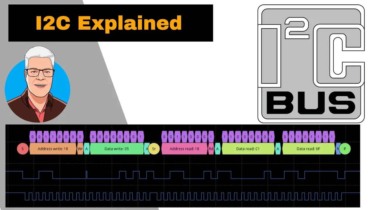
An introduction to the I2C communication protocol, including the roles of SDA (Serial Data) and SCL (Serial Clock) lines.
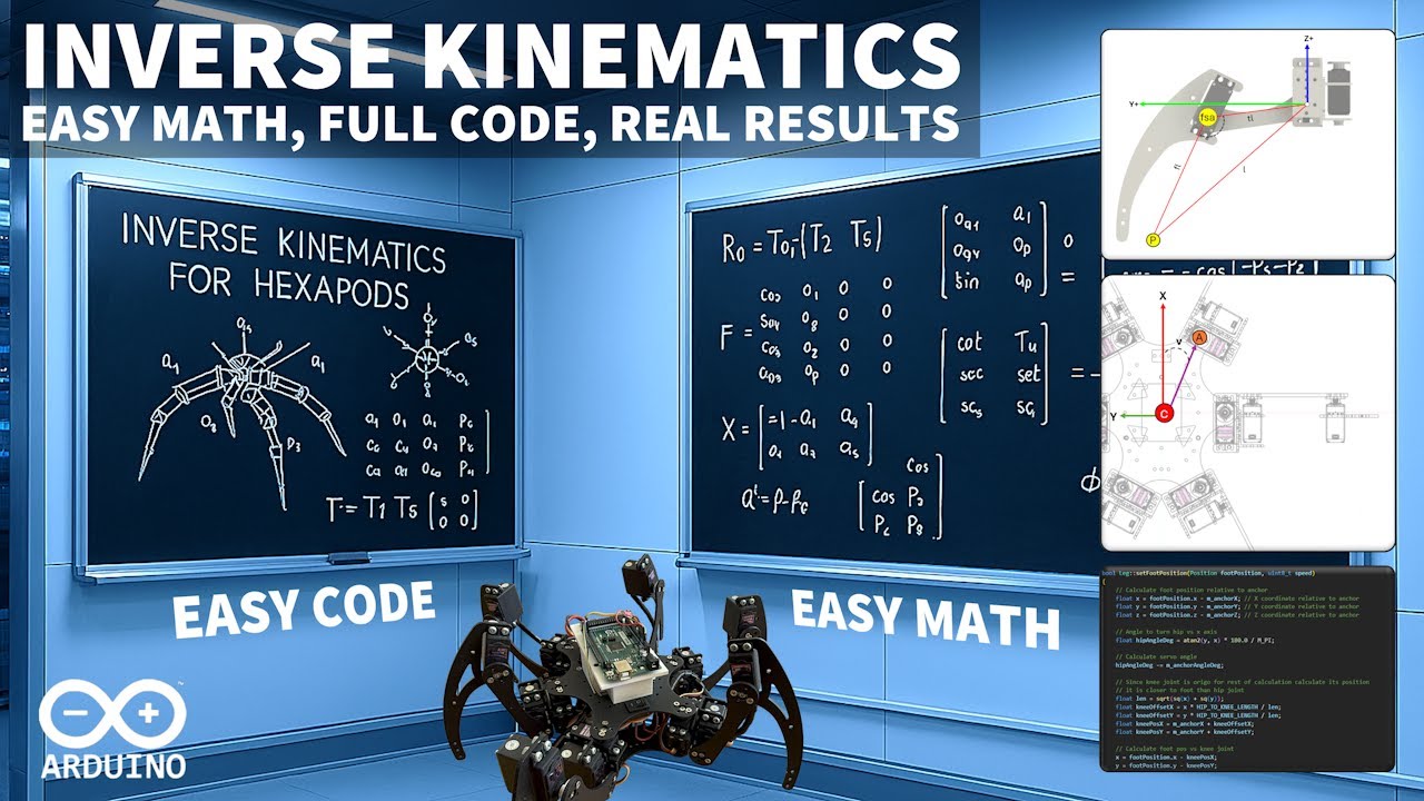
Designing and programming complex multi-joint systems, such as robotic arms (inverse kinematics) or hexapod walkers.
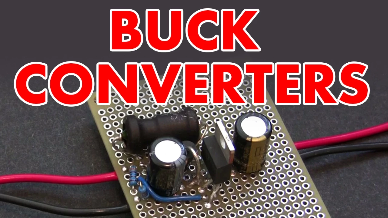
Advanced power distribution strategies, including the use of decoupling capacitors, buck converters, and fuses to manage high current spikes.
Daisy-chaining multiple PCA9685 boards via hardware address modifications to control up to 992 servos from a single microcontroller.
Implementing motion profiling algorithms (such as ease-in/ease-out curves) to achieve smooth, natural movements rather than abrupt speed changes.
11.7K views211likes6:22Original Release: 2025-02-09
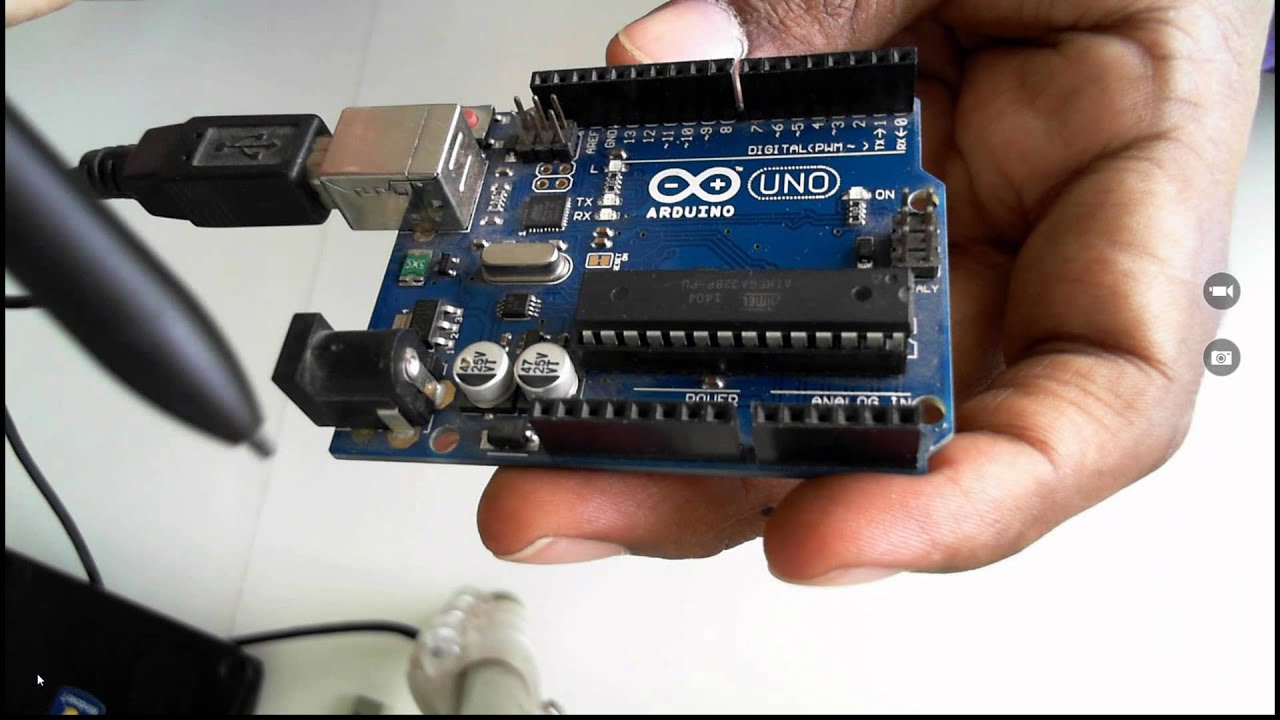
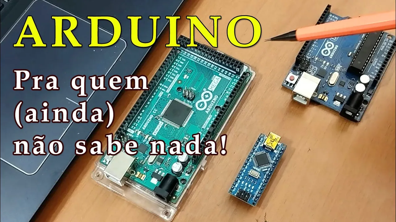
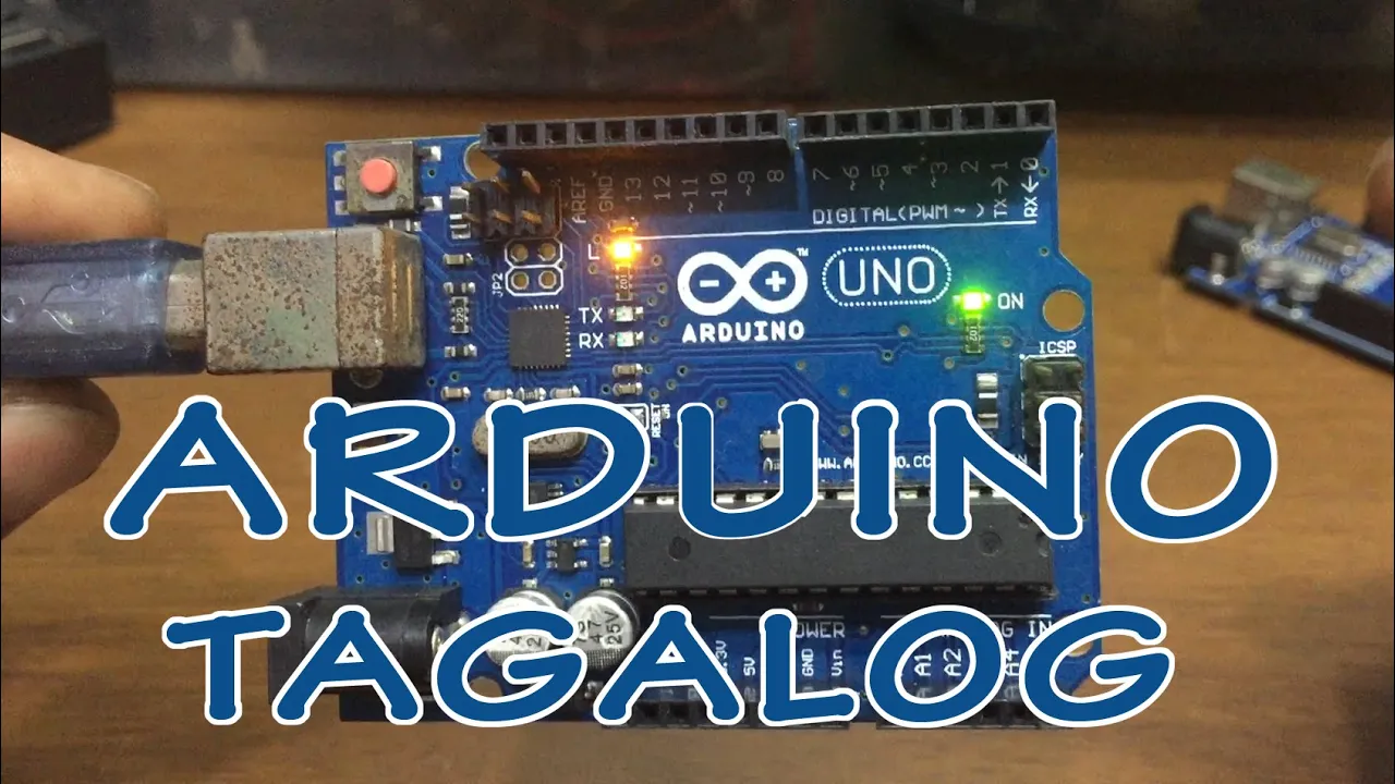
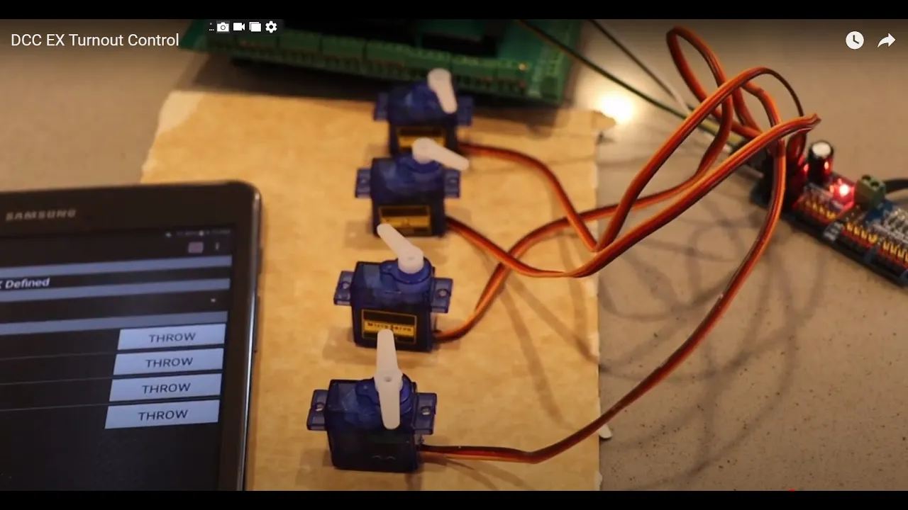
today we're going to see how to power and wire 16 Servo motors for Arduino using the PCA 9685 pwm driver I'm going to be using 5vt power so the first thing I want to do is show you how I decide which power supply to use let's get started I don't have 16 of the same Servo Motors So today we're going to use four of the small sg90 servos we're going to use some mg995 servos and then some Mizu MIUI 996 which is basically a clone the mg996 there aren't any fundamental discrepancies when using these three different Servo motors with the same PCA 9685 board but you also want to take a couple things into account and one of those things is pwm frequency most of these hobby servos are going to operate at 50 HZ and all three of these do you also want to consider the pulse width range calibration the typical pulse width for these hobby servos is approximately 500 to 2500 micr seconds so keep in mind even if they share voltage and frequency if you're mixing your servos like we are here today they may have different torque speed and precision characteristics and that could show up in performance differences in your project maybe you can't find the data sheet or you just want to see for yourself just an estimate of the current that this thing draws when it's moving it's at 5vt no load so let's go ahead and take a look I've connected it to a a desktop power supply and it's running at 4.9 volt 4.99 we're going to turn that up a little bit to five not that it matters but you can see that it goes up to about 300 milliamp when it turns and then resting is about 12 at 5 volt and of course if you turn that up uh it'll obviously draw more current and turn it up to six 6.07 and you can see it draws a little more current it's in the 400s 460 something like that and uh you can definitely tell that it's it sounds a little bit different it feels like it's working a lot harder so it's going to draw more current but that's just a it's not an analytical exact value but it is just a a rough estimate of what one will draw when it's just connected to uh to a board with no load while this may be okay with small projects you may want a more precise reading with a multimeter we can connect the ground pin and a signal pin to the Arduino and insert the multimeter in series with the servo so that all the current flows through the meter we'll do this by connecting the ground rail of the breadboard to both the servo motor and the Arduino and the signal pin of the servo motor to Arduino pin number nine for me and I'll connect the comp Port of the multimeter to the Power Pin of the servo motor and the a port of the multimeter to the 5volt rail the breadboard and you can see I get anywhere from 129 milliamps to 279 milliamps now if I have 16 Servo Motors just like this if I multiply this current by 16 it would give me a safe upper bound if every motor were to draw the maximum current simultaneously however in many practical situations you might not need a power supply for exactly the worst case scenario especially if all the motors won't be under full load at the same time you'll see here in this project that all the wires connected to the lever connectors are all power power pins to the Sero Motors and all the servo Motors are powered by an external power supply to determine which power supply I need I'm going to multiply 600 because that's the largest current value that I measured multiply that by 16 the number of servos and that gives me 9,600 milliamps that I need for my project and I always add 20% on top of what I need just for overhead so things don't heat up so that's an extra 2,000 milliamps so in this case a 5V 15 amp power supply would be more than sufficient for the wiring I have the Arduino and the PCA 9685 board controlling the signal for the servos all the servos are powered by the external power supply here's a look at the diagram with just four Servo Motors I wanted to keep it at four so that I didn't overcrowd the image here are all the ground connections for this project and they are connected to a terminal block along with negative power supply you also want to make sure your wires are sized appropriately for the current that they are expected to carry you may also want to consider some capacitors at the power source to help with voltage stability I connected the PCA 968 85 board to Arduino using I Square C pins SDA and connect the VCC to 5vt and ground to ground I connected 5vt from the power supply directly to a lever terminal and then distributed that to four other lever terminals where they were connected to the servo Motors and here I made them actually just do a bunch of random movements the other pins from the servo motor when I connected those to the PCA 9685 board I just used the pwm pin and the ground pen I did not use the v+ pen because we're powering our Servo Motors using external power so I didn't use any of the v+ pens on this board and the only reason I would use this side of the board is if I was to expand to another PCA 9685 board so here's one last look at my diagram and of course you would add more servos the same way I did these for right here and here's a look at my setup this is actually a power supply that I use for LEDs it is a variable power supply 20 volt 20 amp and the length of the wire and the gauge of the wire will have an effect on power supply so keep that in mind you don't want some really long wire the shorter the better and you want the correct gauge so that it doesn't get hot and overheat that's about it it's pretty simple this is how I set up my uh project if it requires more than 10 amps you shouldn't put 10 amps more than 10 amps through this PCA 9685 board so I hope this was helpful so this is how I do it I'm sure there are other ways to to do this and probably better ways if you know of a better way go ahead and leave it in the comment I'd be interested to hear about it you definitely want to do your own research before setting up something like this to make sure you're getting the best for your project you don't want to just blindly put this stuff together so be careful when working with high current as well well that's all I've got for you today I hope you like the video if you found it useful be sure to like the video by clicking the thumbs up also share it with anybody else who may find it useful and I'll see you again with another project
Up Next
20:42
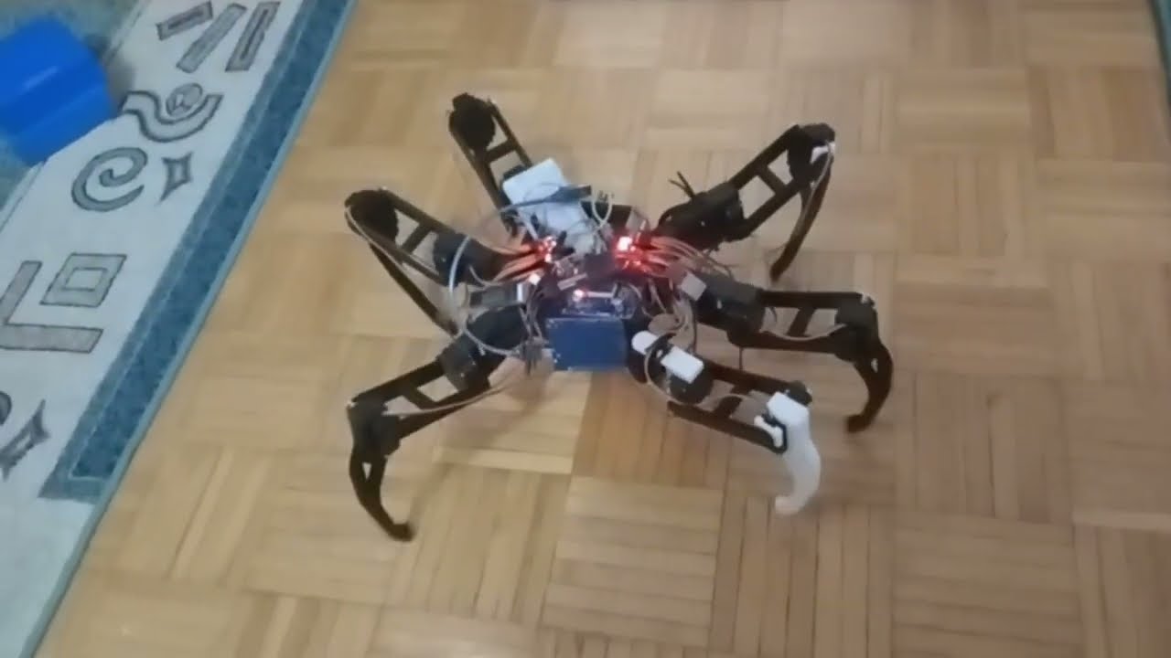
Arduino Hexapod Robot: Construction and Control
@HowToMechatronics
221.1K views•2018-12-11

12:54
Triumph of Orthodoxy Icon: Byzantine Art & History Explained
@BenCallan
2.1K views•2024-08-06

9:49
FastAPI vs Flask vs Django: Choosing the Right Python Web Framework
@TechWithTim
302.5K views•2024-05-26

1:42
Game of Thrones Opening Credits: A Cinematic Analysis
@gameofthrones
46.3M views•2011-04-18
Related Study Plans & Knowledge Roadmaps
Structured learning paths in General & Interdisciplinary Studies
general-studies
Elevator Engineering: History, Physics & Cities
01From Hoists to Safety Brakes: The Dawn of Vertical Lift
02Hydraulic vs. Traction: The Engineering Physics of Elevators
03Modern Speed, Safety, and Algorithms
+ 2 more learning modules
12h5 modules
Explore Roadmap
general-studies
Rubber: Material Science, History & Geopolitics
01Origins of Natural Rubber & Mesoamerican History
02The Chemistry of Natural Rubber & Vulcanization
03The Geopolitics of the Rubber Boom & Colonization
+ 2 more learning modules
12h5 modules
Explore Roadmap
general-studies
Containerization: Evolution, Logistics & Trade
01Ancient Trade & Bulk Cargo: Amphorae to Barrels
02The Industrial Revolution & Cardboard Packaging
03The Containerization Revolution: Malcom McLean
+ 2 more learning modules
12h5 modules
Explore Roadmap
general-studies
Textile Tech: Evolution, Labor & Global Impact
01Pre-Industrial Textiles: Handloom & Cottage Industry
02Mechanization: The Spinning Jenny to the Power Loom
03The Factory System & Global Labor Transformation
+ 2 more learning modules
10h5 modules
Explore Roadmap