







![0105 Navigating using a three button mouse and keyboard shortcuts [繁中字幕]](https://i.ytimg.com/vi/GMa4Luo3rXU/sddefault.jpg)








This tutorial demonstrates how to create a custom Maker Coin for 3D printing using Autodesk Fusion 360, covering essential CAD concepts including setting up preferences for 3D printing (changing units to metric, adjusting modeling orientation to Z-up, and customizing shortcuts), the parametric modeling workflow (starting with sketches, using extrude to create 3D bodies, applying circular patterns for symmetry, creating extrude cuts for recesses, importing SVG files for logos, and using revolve cuts for angular details), and the importance of proper dimensioning and constraints to enable easy modifications later.
Fusion 360 Beginners Guide: Design & 3D Print a Maker Coin
Added:Basic understanding of 3D printing fundamentals, including how FDM (Fused Deposition Modeling) printers operate and the role of filament.
Familiarity with basic 2D geometry concepts such as coordinate systems (X, Y, Z axes), dimensions, and geometric constraints.
An introductory awareness of Computer-Aided Design (CAD) workflows, specifically the concept of extruding 2D sketches into 3D objects.
Basic computer navigation skills, including how to install software and use a three-button mouse for viewport navigation (pan, zoom, orbit).
Mastering advanced parametric modeling in Fusion 360, such as defining user parameters and equations for dynamic, easily adjustable designs.
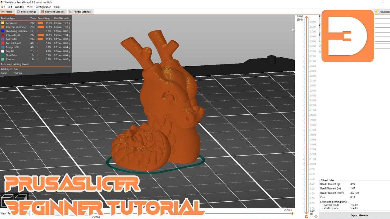
Exploring slicing software (e.g., Cura, PrusaSlicer) parameters like layer height, infill density, and wall count to optimize print quality for filament testing.
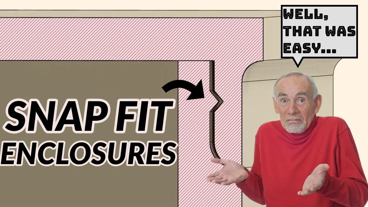
Designing multi-part assemblies with precise tolerances and functional joints (e.g., snap-fits, threads, or print-in-place mechanisms).
Understanding 'Design for Additive Manufacturing' (DFAM) principles, focusing on overhang angles, bridging, and minimizing the need for support material.
Post-processing techniques for 3D printed models, including sanding, priming, painting, and heat treatment to achieve professional finishes.
271.9K views6.6Klikes25:35Original Release: 2017-03-31
These are maker coins. So, last year I wanted to come up with a way to repeatedly test sample filaments that I could try out on my 3D printers and end up with little, I guess, swatches of those filaments. You don't often get very much in sample packs and wanted to make most of them in a repeatable object. So, I came up with the Maker Coin that I designed last year in On Shape. Well, step forward a year and the Maker Coin concept has been widely adopted by the community, which is awesome. But now it's 2017, so I think it's right time to update my tutorial on how to model a maker coin from the ground up using Fusion 360. If you love 3D printing, but you've never 3D modeled anything before, then this is the video for you. Let's get [Music] started. Welcome back to Makers Muse, guys. So, as I said, this is a beginners's tutorial on how to model a maker coin in Fusion 360, and it's aimed at beginners who have never really experienced 3D modeling before. So, it may be at a speed that is a little bit slow to you if you've got experience in Fusion or other CAD programs. But before we do anything, I first need to establish the fact that you need to change a few things in your defaults to make the experience as seamless as possible for 3D printing. So, fire up Fusion 360. And what we're going to do is go into preferences on the right hand side. So drop down preferences. The first preference you need to change is units. So depending on what style of units you like to model in, imperial or metric, you need to change your units to reflect that. So I model in metric. So I model in millimeters. So here on the preferences, default units, design, I have my design units, my cam units.
Don't worry about that for now, for now.
And simulation units all set to metric measurements. So you can see I've got mass is kilg, length is millimeters, time in seconds, force in newtons and so on so forth. So if you are in America and you like to work in imperial, you need to change these to suit. Next to change is your modeling preferences. So I have come from a Solid Works background. So I've changed my pan, zoom, and orbit shortcuts to Solid Works. But if you're just starting out, you may prefer to use Fusion's native shortcuts. Or you may want to choose something else from Alias or Inventor.
Either way, these are designed to just make you more comfortable with the program. Everyone has their own preferences. Neither is better or worse.
And one final tip for 3D modeling. For 3D printing, you want to change your default modeling orientation. So Y up is a standard for 3D CAD, but for 3D printing, we want Z up or Z up. And that's because your 3D printer has the X, the Y, and the Z. The Z is height for 3D printing. So when you're modeling stuff with the Z up, then your prints will come out into your slicer in the correct orientation. If you model with YU up, they'll come out on their side.
And it's a little bit confusing. It's a little bit of a time waste to flip them around. So, I recommend this to change this. And some of you guys who have been using Fusion 360 for some time might not have even known this. So, there you go.
So, apply. We've got our default settings. And there is others you can change, but for right now, that's all we need. So the basis of 3D modeling is to take an idea and create it in three dimensions in your computer design software. So before I model anything, I take a pad and a pen or pencil and I try to draw what I want to model. And there's a few reasons why this is good practice. You don't want to be limited by your knowledge of a program. If you model straight into the software without thinking and drawing what you want, you're going to end up drawing what you're comfortable with in the software, and that's not a good way to do it. What you want to do is try to draw what you want on paper and then work out how to do it in the software. It's a better practice, and it means you won't be limited with your knowledge of a piece of software. Okay, so I've roughly drawn what I want to model. And keep note, I can't draw at all, but I still do this.
It's still good practice. So, what I've drawn for my design, and again, this is my design. You can draw what you like.
This is just a tutorial to get you started. I've drawn like this sort of Beyblade style design with my logo in the middle. And this is a sideon view of the idea that I want it to sort of have these edges to slope into each other so they become these like sharp points.
They probably won't be very sharp. It is 3D printed. And yeah, that's sort of what I want to go for. So, this is just a rough, but it's to give you an idea of where to go. It's always difficult to start with a blank canvas. And it's even more difficult when that canvas is in three dimensions. So good Fusion 360 practice before you do anything is to create a component. And the component will store all the sketches and features that we create within it. So to do that, what we want to do is go up above assemble and new component. So I'm going to call this Maker Coin. There we go. And it shows up on the left hand side.
So, Fusion 360 can operate in a manner of of ways. But in this video, I'm going to show you how to operate it using parametric modeling, which means you start with features and sketches and you can go back and change them and everything will update in future. You can use Fusion in a pushpull or organic modeling method, but that's not something that I do. It's not something I'm going to cover in this video. And it's good because if we design this and we want to change details of it, we can by doing it through this technique, through this method. So to start, we need a sketch. And to create a sketch, we need to define where it should be in space. So on the left hand side, I'm going to click this little uh light bulb to show origins and planes. So because we're working in three dimensions, we have three planes and we have an origin, which is 0 0. It's it's right in the center of this 3D space. And to create a sketch, we need to define where that is in that space. And also on the right hand side to help you navigate, it actually shows you what the different views are. So we have front, top, and you can actually click them. It'll automatically go straight on top of them. So, and we have right as well. But for our sketch, I want to go from the top down. So to do that, I'm going to click sketch and then the top plane. You can hover over it, select, and we're now sketching on the top plane. So the easiest way to start this would be to start with a circle, I'm going to say.
So I'm going to start with a circle and then work my way from there. So to select circle, you go to sketch and then you can select anything from this drop down. A sketch can have any sort of line. It can have curved lines. It can have rectangles, polygons, but it can't have any sort of 3D data because the sketch is used to create 3D data later on. But it's also important to learn the hot keys of Fusion. So a line is L and a circle is C. There's different types of circles, but we want the center diameter. That's the easiest one to use for what we're doing now. And it's important to learn the hotkeys because you can model a lot faster. So, I'm going to hit C on my keyboard. And now I can click the center, which is our origin, and we can specify how large our circle is. So, again, millimeter units for me. And because I made my shape 40 overall with the the teeth, I'm going to make it 30. Let's go with that. So, let's go with 30. Enter. And you'll notice the sketch goes black. And that's because it's now locked in place. We've defined that the center is at the origin and that the actual circle is 30 mm in diameter. It can't move anywhere.
However, if we did make a circle for example just like this arbitrarily, you notice that this circle is blue. It can be moved in space and its diameter is not fixed. So, it's important to define things. It's a good practice and it means that later on things aren't going to change without your knowledge. So, it's good practice to get into when you're making very accurate mechanical designs. You can get away with it if you're doing more free form things, but if you need something to fit into something else, you probably should dimension it. So, we've got our circle.
Now, we need to actually give it some thickness. Right now, it's just a zero thickness sketch. There's nothing to it.
So, to do that, we're going to create an extrude. And extrudes are the the heart and soul of 3D modeling. Uh, it's definitely the one of the more common commands you will do, more common features. So, create and extrude. Again, you could hit E, another good shortcut. And it wants us to select our profile, which is the circle. And it wants to select how much depth we give it, how thick it is. So, you can drag it to get an idea. But I did write 8 mm in my sketch. So, I'm going to see what eight looks like. Hit eight. And that looks maybe a bit too thick. So, maybe I'll go with six.
Keep in mind what we drew before was just a guide. Six looks a bit better. Um I did I am going to cut away a little bit later. So yeah, let's go with six.
That looks good. And there's different operations, but because this is the first solid we're drawing, it's a new body. So new body. Okay. Now, we need to add some teeth. Now, I could have added the teeth at the same time in the previous sketch, but it's good practice to keep sketches simple. If you add more details, they get complicated and you can break them pretty simply, pretty easily. So again, sketch, and we want to select the front plane again. So you notice that it's sort of suggesting where I want to click. I could select the top of this new extrude, but we actually just want that front plane again, like that. Now, the teeth look kind of complicated, but really they're just two circles. They're just in space at a certain size and distance from each other that they create that tooth profile. So we're going to hit C again for circle. That's going to draw two arbitrarily like this.
And now I'm just going to move and size them till they kind of look like teeth.
So let's move that one, I guess, there.
This one here. So I'm going to now just define them so they don't move in space.
So just D. Make that one 25. And make this one 15, I suppose.
Yeah, let's go with that. Maybe a bit too sharp on that top part there. Let's move it here. That looks pretty good. And now I'm just going to lock them to where they are in space. So to do that, we're just going to dimension them to the origin. Remember, the origin can't change. It's locked. It is 00 0 in space. So seven. And to dimension them from the origin, you're going to need to dimension them how far they are up and how far they are across. So each one needs two dimensions to their center point, like this.
Two. And final one here, 14. and 11. So for a maker coin, this kind of dimensioning is probably overkill, but it is very good practice to get into modeling like this later on when you're doing more complicated designs. So one thing we need to do before we exit this is we've got our profiles. You see, I'll hover over them, it'll highlight, but currently it's not going to select the outline of our previous shape. So we need to do what's called a project. So a project will take that shape and pretty much bring us a line that we can use into this sketch.
So we can go to sketch and project or include project. Again the shortcut is P. A lot easier to select P than go through the menu and select geometry. That and a projected line looks pink. So you can probably barely see it there. But now when we select over hover over areas, we can actually get that tooth profile correctly. So stop sketch and extrude. And now we can just select our tooth profile. And you can arbitrarily drag it as well, but I'm going to show you a way you can make sure it's always perfectly aligned with that top face, even if we change that extrude. So we go to extent and we want to select to object. And the object is this. And you need to select the right chain faces method. So it's not this one. It's extend the faces to the end of the object.
like that. And we want to join. We don't want to cut. We don't want to make a new body. We want to join it together like that. So, we've got our tooth, which is pretty cool. Now, we need to make more of them. And that's actually pretty simple. So, we're going to do what's called a circular pattern. So, a pattern takes an object or a feature and will either pattern it in X, Y, or Z distances. So, just make copies of it.
Or you can do a rotational pattern, which will then go around an object. So that's what we want for our tooth. So we're going to go to create and pattern circular pattern. And the pattern type we want is features because we want to pattern just that extrude that we just made. So features.
And the easiest way to select it would be to go down to the bottom left where we've got our different features in the feature tree. So extrude. And the axi is going to be the outside of our circle or cylinder. So there we go. It's going to ghost out what it's going to look like.
So, it's got three teeth there. We could give it five if you wanted to, but I think three is enough. Three looks good.
All right. So, we got our Beybladey looking thing so far. Looks pretty cool. Hey, cool. Okay, so we've got our Beyblade looking shape. Now, what's next? So, we want to give the inside bit a bit of a recess where I'm going to put my logo.
So to do that, you can probably guess it's another extrude, but it's an extrude cut. An extrude cut will remove material instead of an extrude, which will then normally add material. So to do this, we're going to select sketch.
You're probably picking up a pattern here. Everything starts with a sketch.
And instead of selecting the plane, we're going to select the top of our maker coin. So select here. Top. Excellent. Okay. So, circle, remember, hotkey C. Select the center of the object. And then we're going to bring that out. So, I I'm just going to guess what looks good, I guess. So, maybe what looks decent. 24. 24 looks good. Happy with that. Nice. Cool. Okay, I'm happy with that. Stop sketch and extrude again. Select what we just drew. And the really cool thing about Fusion is it automatically detects what you're trying to do. So if I pull this down, it automatically switches to cut cuz you're not going to extrude into an object that already exists. Doesn't make sense, but you are going to cut into it.
So you see here that we can cut right down into the shape. But I did draw in my little thing here a sort of angle. And that's easy to achieve by changing our taper angle. So here in the extrude window we have taper angle and I'm going to enter 45. So 45 goes out and that's not what we want. We want to do the other way. So minus 45. And that looks pretty sweet to me. Nice. Okay. And minus two. I suppose that's minus two. Looks pretty good.
Maybe minus Yeah. Okay. Minus two.
And again, you can go back and change any of these things. In fact, now looking at this coin, it doesn't leave us much room for my logo. So, I'm going to change that sketch. So, I'm going to go to the bottom here on the left, right click, edit sketch, and change it from 24 to 28. So, it's more close to the edge of our original shape. Stop sketch automatically updates and adds that nice angle in, which is known as a shamfer, by the way. You can do that individually. Okay, now's the fun part.
So, this is where we want to add our logo onto our maker coin. And this can be a little bit tricky, I will be honest, and it can be a little bit annoying in some aspects, but we're going to try to go through it. So, I'm going to fire up Illustrator here. This is my watermark that I want to turn into a imprint on my Maker Coin. So, before I begin, I just going to get rid of stuff I don't want. So, get rid of that. So, I'm just going to scale my logo in Illustrator before I bring it in. So, 23 mm. There you go. A lot smaller than it would have been brought in otherwise.
So, file, uh, export, export as, and scaled logo. There we go. And these settings seem to work pretty good. Okay, back in Fusion, we want to drop our SVG in. So, I'm going to go to insert, insert SVG, and we're going to select our scaled logo and bring this across into place.
Notice because we scaled it, it's easy to put into place in the right size. And we can rotate it as well. So, I'm going to rotate this around 180° and just drop it in the center here. I might make it a little bit larger. So, maybe 1.2. That seems to look pretty good.
Yeah. Sweet. And you notice that yes, I did say importing SVGs can be buggy.
We've lost a line here for some reason.
So, I'm going to say okay. And I'm just going to hit L for line and just add a line in to patch that up because otherwise we can't use it to do any features. Okay. So, we've got our SVG.
It's in the right position. Stop our sketch and extrude. And I'm going to do another cut. And this time, I'm going to do 0.
So, minus0.5 like that. And I might do a slight taper angle. Maybe uh minus5. That's too much. Maybe minus 5. Doesn't really do anything, but okay.
Right. So, we've got our logo indented into our object. And if you're having troubles with that, just try a few different settings. Make sure you export it at sort of the right scale to begin with. It'll save you a lot of trouble.
Okay. So, one final thing I want to do to our coin, then we'll be complete, is to give our teeth a nice sort of sharp edge, I suppose, by adding some sort of angles to them like that. So, to do that, I'm going to do a revolve. Now, a revolve is a very powerful feature where it takes a profile and spins it around.
You can see my revolve, my tutorial on making this bottle where I used a revolve if you want to see a more advanced Fusion 360 video after this one. But I'm going to use a revolve cut to cut those profiles into my teeth. So create sketch. And in this case, we're going to want to select let's go with the front plane like that. Okay. So let's select a line L. And let's sort of arbitrarily look at where we want to cut. Maybe like that. And I'm going to block it off like this. So imagine this is a tool. It's just going to spin around our object and cut as it goes.
You know, like you're lathinging something. So, I want to define how much it's cutting. I don't want a sharp point. I want it to kind of have a little bit of meat there. So, I'm going to hit D for dimension. And I'm going to make these two here. Notice it automatically defined a uh it automatically brought in a projected line for us to work on, which is handy.
45°. And I'm going to also make the top one 45° as well. So, dimension here, 45°.
Okay. Now, I'm going to make sure that it's not going to cut in too much. So, I'm going to bring it out just a little bit from the side of the shape. So, let's go to dimension again, click our point, and click the edge of the tooth.
Maybe one mm off. So, you notice our object's still blue. It's blue for a number of reasons, but the one thing we want to make sure that's locked in space is that this part here cuts the center of this line. We can do that using a construction line and what's called a mid midpoint relation. And a midpoint relation will lock our part into the middle of a line. So, we're going to draw a line L from our point across.
Select the point of that line and select by holding shift the line that's as part of the tooth. Right click that and Fusion will automatically suggest relations. And relations are extremely powerful. Not going to go into them too much in this video. It's just a beginner's guide. But for midpoint, you notice it locks it straight to the middle of this line. It can no longer move. And by doing that single relation, this whole object for the parts we care about at least are locked. We don't really care about this because it's it's a tool it's cutting around. We only care about where it's intersecting our object. So in this case, I'm not going to fully dimension just because it's not needed. I'm going to say stop sketch. So now I'm going to rotate this tool around our maker coin to cut away the details we want. So let's go to create and revolve and the profile, which is our tool. We want to select, make sure we select all the parts we want to cut.
So those are all of them like that. And the axi that it's going to rotate around. You can define your own axi but in this case we can actually just select the center of our object here. Can be a little bit tricky. There we go. And it automatically suggests cut because we're cutting into the object.
And okay. And check that out. So, with that one simple feature, that revolve, we've added some really sweet details to our teeth on our Maker Coin. So, let's backtrack. What have we done in this video? So, let's on our feature tree, scroll back all the way to the start.
And let's make sure everything is shown.
So, we started with a circle. We then took this circle and we extruded it up by 6 mm.
We then drew a sketch which was the detail for our teeth which we did by defining some circles in space and defining the intersecting area that we wanted to make our tooth. We then extruded that tooth up to the top of our maker coin by using the up to object uh function in the extrude function. We then made more teeth by rotating it around with a rotational pattern.
Then we defined where we wanted to cut into our object to create our recess. So it's an extrude cut with a taper angle of 45° or minus minus 45°. Then we brought in our logo which is arguably the more uh difficult part of this exercise. And then we extrude cut that logo into our maker coin. And then finally, we defined a revolve cut to give our teeth some angles, some sharp edges to it, which we then revolve cut around our object. So, why would we put all this effort into defining something correctly? Well, let's say we want to make the teeth bigger. Let's say we want to make them a bit more aggressive. So, let's go to our teeth sketch. Right click, edit sketch. And you see this is the profile for our tooth. Let's say we made this 30. So, they're a lot larger. Stop sketch. And just like that, guys, everything updates nicely. And our Mega Coin has some massive chunky teeth on it. Because we defined everything properly, it will update correctly. Now, sometimes things might get a bit confused, but it's usually pretty easy to go in and redefine things slightly to make them work. And I can just go backwards like that, and it's back to normal. So, there you go, guys. That's how to make your first maker coin in Fusion 360. I hope you found this video useful and I hope it kickstarts your experimentation and modeling in 3D for 3D printing. Really, it's not that difficult. You just need to start with a sketch, an idea of what you want to do, then work out how to do that in your 3D software. So, if you want to actually print this model, you can just go to rightclick it and then export or save as an STL. Make sure send to 3D print utility is unticked because you want to just save it. Okay. And save it as Megacoin like that. All right, guys. Well, here we are. So, these are the maker coins we just designed. So, they're a little bit small, but again, we put all of that effort into our original model in Fusion 360. So, you can go back in, edit dimensions, and make them how exactly how you like. I usually say that with designs, usually get three shots before it's perfect. First shot gets most of the bugs out. Second time, fine iteration, and then third time is usually the perfect one. So, I reckon three, three from here, we'd have the perfect make a coin. So, thanks for watching everyone. Hope you enjoyed this video here on Makers Muse and this tutorial in Fusion 360. And if you don't want to miss future 3D printing tips, tricks, and tutorials, and reviews, hit the subscribe button. Helps us out a huge amount. And I look forward to seeing you again very shortly. Catch later, guys. Bye.
Here's the weather of the 20th century, and man has sent rockets into deep space.
He has placed satellites in
Up Next

3:11
EMG Signal Rectification with MATLAB and Arduino: A Step-by-Step Demo
@Challenger-Tech
1.2K views•2015-10-18

12:54
Triumph of Orthodoxy Icon: Byzantine Art & History Explained
@BenCallan
2.1K views•2024-08-06
24:59
Build Your Own Remote-Controlled Robot Platform: A DIY Guide
@MakersMuse
102.9K views•2021-04-09

1:42
Game of Thrones Opening Credits: A Cinematic Analysis
@gameofthrones
46.3M views•2011-04-18
Related Study Plans & Knowledge Roadmaps
Structured learning paths in General & Interdisciplinary Studies
general-studies
Elevator Engineering: History, Physics & Cities
01From Hoists to Safety Brakes: The Dawn of Vertical Lift
02Hydraulic vs. Traction: The Engineering Physics of Elevators
03Modern Speed, Safety, and Algorithms
+ 2 more learning modules
12h5 modules
Explore Roadmap
general-studies
Rubber: Material Science, History & Geopolitics
01Origins of Natural Rubber & Mesoamerican History
02The Chemistry of Natural Rubber & Vulcanization
03The Geopolitics of the Rubber Boom & Colonization
+ 2 more learning modules
12h5 modules
Explore Roadmap
general-studies
Containerization: Evolution, Logistics & Trade
01Ancient Trade & Bulk Cargo: Amphorae to Barrels
02The Industrial Revolution & Cardboard Packaging
03The Containerization Revolution: Malcom McLean
+ 2 more learning modules
12h5 modules
Explore Roadmap
general-studies
Textile Tech: Evolution, Labor & Global Impact
01Pre-Industrial Textiles: Handloom & Cottage Industry
02Mechanization: The Spinning Jenny to the Power Loom
03The Factory System & Global Labor Transformation
+ 2 more learning modules
10h5 modules
Explore Roadmap