








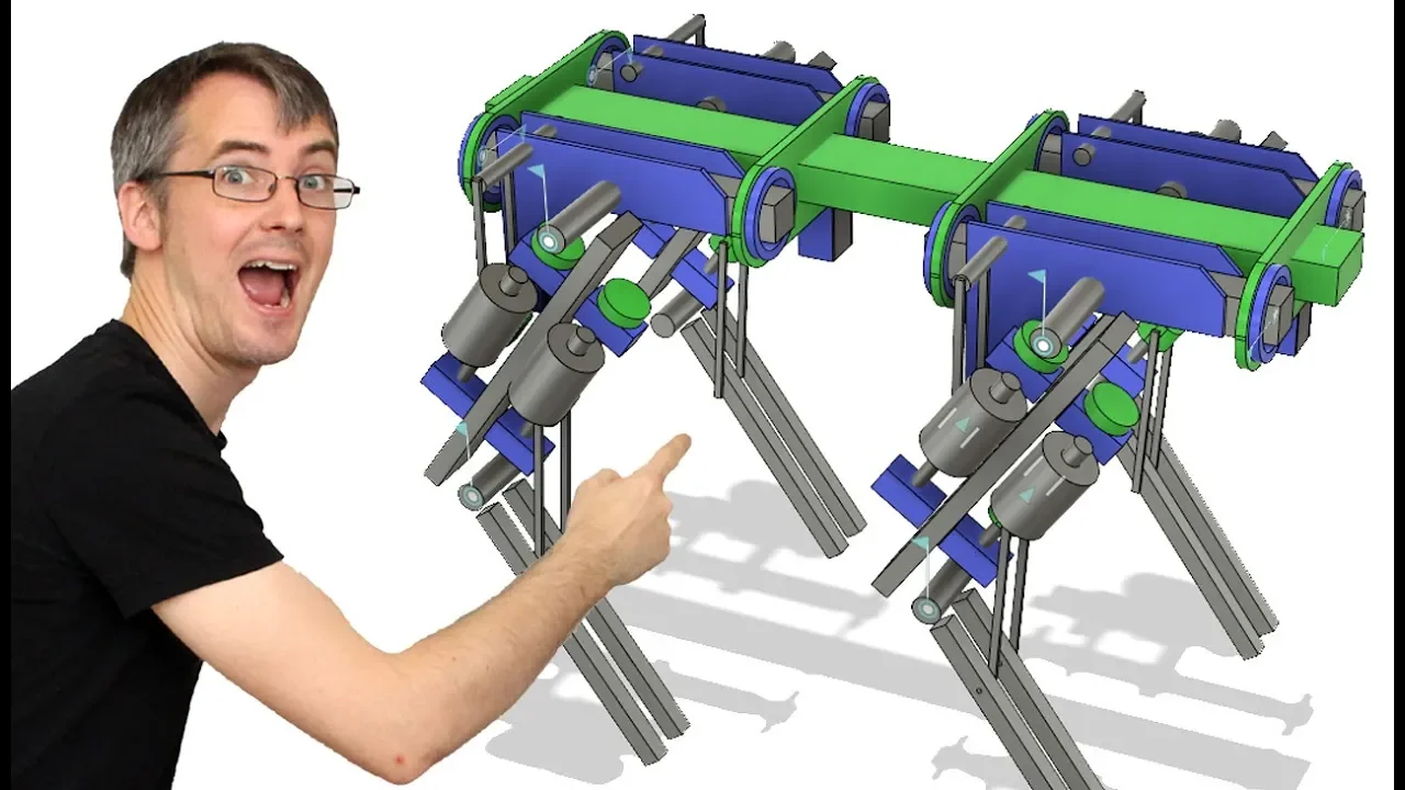










This video demonstrates the prototyping of a single leg for an open-source robot dog (openDog), featuring 12 brushless motors with encoders driving ball screws for precise leg movement. The design uses inverse kinematics to calculate joint angles from desired leg positions, with trigonometric modeling enabling accurate control. Key mechanical components include SFU 16:05 ball screws (16mm diameter, 5mm pitch), 2060 T-slot extrusions for structural support, and V-wheels running in T-slots to prevent rotation. The control system uses ODrive motor drivers with 8,192 encoder counts per revolution, requiring approximately 3,490 encoder clicks for 100mm of linear travel after accounting for belt reduction. The project employs 3D printed prototypes for initial testing before transitioning to CNC-machined aluminum parts, with code published under GPL 3 license on GitHub for community contribution.
Prototyping a Quadruped Robot Leg with Brushless Actuators
Added:hello is James here this is part 2 of the open dog project which is an open source dog robot project it's gonna be pretty big about 900 mil and stands about 600 mil tall so about the same sizes boss and dynamic spot mini robots but not quite as good as that because I'm not as good as Boston Dynamics so last time we looked at the overall design in CAD we list some code and we looked at the old drive for robotics brushless motor driver so this robot it's gonna have 12 brushless motors and encoders on them and ball screws and it's gonna be made of metal that I'm gonna see and see and some 3d printed parts and some extrusion and all sorts of stuff like that so this time we're gonna delve into that design a bit more in one leg we can look at some of those detail parts of actual metal and mechanics and things like that we're gonna try and make one knee joint now we're going to look at the code again and check that we can control it before we go and buy all of those motors even though I've already bought lots of them and all of the motor drivers and all the other stuff then after that we can pretty much get on and build it so here's the cattle I drew last time which I published and you can find a link to my github in the description to get this cat and the CAD and code from this episode as well but this time we're going to concentrate on one lake so I've built these joints that work so the basic aim is you've got this brushless motor driving a ball screw a bit like the way we did the exosuit and obviously that's gonna move the leg and we work out the trigonometry to work out the inverse kinematic model that I explained last time so we can count to plate with joint angles and essentially that's how it's all gonna hang together and I drew this CAD in quite a crude way so I mean the ball screw is there and it's roughly the right size but actually looking at the physical parts some of these blocks of different shapes this is a t-slot extrusion and I really wanted a wheel that ran up and down that so I need to change the placement slightly and actually measure the real-world parts now I've got them and try and work out how that's actually going to look and then we can actually put the motor on there with a belt obviously there's no bracket the hinges are floating in the air so we do need to work out those details so here are some of the physical parts we've got is an SFU 16:05 ball screw which is 16 mil diameter and a 5 mil pitch that's got any machining down to 10 mil I think it is on this ends and it's got these bearing blocks and that fits each end so that's my 2060 extrusion which makes up the thigh essentially and these will be mounted of course sort of in there and there's another one on the other side which operates the upper leg and then we've got a motor which will be mounted like that two of those and that will run or C down to here so this will be on the piece of the bull screw there I'll be running a pulley like we did in the exosuit and I'm probably going to attach this back to this block there's got holes in the top the same as we did exactly the same as before so then we've got our knee joints which sits there somewhere and obviously the rod that comes across and we want to make that perfect triangle so the maths is easy to sort out so essentially we need to put a rod that goes from the middle of that into the middle of this and with the exosuit we left this completely unsupported because the ball screw is pretty strong and I think it is probably strong enough it won't Bend the ball screw but since I've got this 2060 V slot here what I really want is a little wheel that will run in that V slot or two to help support this and also want to stop this twisting so um the plan is going to be basically to use two of these the wheels to go and run in those slots so if we now lie this t-slot down that basically means we've got to put this on how like this and make a block that goes around this with these V wheels mounted so that means any pressure coming from the top here will be supported by the wheels and because there's two of them that means this can't rotate and it can't twist the rods now I'm pretty sure the rods are going to be a pair of these which m10 studying with these m10 rod ends on there's a slight disadvantage that this thing rotates around when it doesn't really need to which is going to put some extra load on the thing that goes through it because it'll allow it to twist as the rod push is so and that thing of course needs to be actually be attached to this so there's a bit of thinking to do there some of these parts are eventually going to be cnc aluminium but for now we're going to make 3d printed prototype parts and of course i need to position this ball screech exactly right on my t slot so that the wheels run correctly and everything lines up so going from this rather basic sort of design that we've done here to this is now the detailed design with the ball screw mounted at the right dimensions I've actually drawn the blocks the right size with the mounting holes in the ball nut there with its again with its mounting screws in there and so on so this is a much more detailed version you'll notice what I've got now is um on the lower leg we've got this solid piece which looks like a 2040 the original plan was to use two 20/20 spaced out so the rods could go between and I was originally gonna use the end piece of that V slot to run the wheel in so the one on the edge out of the 3/4 now in fact I've decided to run the wheels in both of those and put the ball screw in the middle so that's resulted in the push rods being right on the outside there and we can just put this together in one piece so I may replace those 2020s with a single piece of 2040 but for now we'll use the 2020s for prototyping so the main important thing about this to do the trigonometry was that the ball screw has to be perfectly in line with the pivot and all of these points are pivoted in the middle here so that makes a perfect triangle that's easy to solve there's two potential issues with that one of course is that I do need to get the height of this ball screw right so the wheels running the V properly and that means this plate will need to be adjusted up and down so the holes will be needed to be moved once I put it together to see if it actually works and therefore we'll have to adjust this hole as well so if I now have made these are separate plates so we can sort of fine-tune them eventually there'll be one piece of aluminium which will be CNC now and of course there's another motor on the other side so this will in fact have an opposite piece with another joint to the other ends but for now we're going to 3d print them so we'll make them separately and that makes it easy to slide them up and down and get the spacing correct the other issue is that of course we've got to put some sort of 10 mil pivot in this hole which isn't very deep eventually it could be our minimum we could tap it and we could screw the 10 mil in for now it's going to be plastic but that's only for prototyping and the third issue is we've got to make a 10 mil axle through the 2020 extrusion and that means drilling a massive hole we're just going to make a weak spot in the extrusion where in my snap of course we could put aluminium plates on either side that will probably work okay we'll have to see how that looks in practice with the whole 30 kilogram weight of the robot on its legs although it does have four legs so it'd probably be alright the other choice we've got of course is that we've got this gap here between this face and the rod so we could actually kind of put this piece of 20/40 in a cradle with the bearings did flush to the surface either side at ten mil bearings there and then this could actually be a piece of flat bar and we could stud weld on a piece of ten mil so that makes a rigid right angle at each ends and again we could seat bearings into this block and that would allow us to keep that rod ridges just put bearings into a block here we could probably even get away with a 3d printed piece of plastic and that would be perfectly strong weed then you have to of course hold these rods together with something in the middle so for now I'm just going to drill the holes put the 10 mil studing in a piece of plastic and we use the rod ends we've got for prototyping and checking the code and maths works [Music] [Music] all right so 3d printed that bracket the holes of the motor and that's attached with some tea nuts into the extrusion there and I 3d printed this part and this has just got a hole through with the two wheels attached there so we take that out there that should run quite nicely up and down the V slot so as false pushes those push rods onto this piece that will be braced against the Teasle that's the idea there so this fits in here of constants got some holes that line up to screw that on so that all looks good so far so we've got the bearing blocks of course which then mount onto this red bracket and they have to be perfectly in the right place they also have to be spaced away from it and at the right height so hopefully the holes are in the right place but we need to put the blocks on each end and check these wheels still run properly so I'm going to assemble that and then we can deal with the shim that holds it away and something to support it underneath because of course that leaves a gap right so just use some nuts there as spacers to hold that and that seems it's not too bad actually for first go there is a tiny bit of movement there so those wheels aren't quite in the slots side to side it's okay but they're basically a bit high so I need to take sort of half mil off move those holes down a little bit and then I need to make a shim to replace those nuts that goes around there and comes in the bottom just to support it as well so I've installed those blue shins there which now hold these rigid and this is still a little bit loose unfortunately I think before I couldn't really tell how far to move it because the plastic was bendy now it's quite rigid I can see I probably need to go down another move a meter or something but for now we're going to leave it like that obviously we need to change that in the future and when that red plastic is rigid aluminium will make it much easier to see what's going on it could just be I'll make the hole slightly bigger or slots so I can sort of bed the thing right down when I fit it and that gives me some leeway but that will do for now obviously the wheels rest in the grooves it doesn't rotate and we're only testing so there's not too much load on it so I've got a 3d printed t5 pulley on there which was the same as the exosuit only this one has a grub screw and the others were just push fit so hopefully it won't come off and that will actually be what I'm going to use to start with you may get some aluminium ones made that'll do for now so I'm going to mount the motor get that knee joint mounted at the other end and put that rod in and then we can actually test it so I drilled a hole in my lower leg there for the 10 mil studying to go through but that has actually cut through most of the aluminium so there's hardly anything left there for any strength so I've made these plates then we'll go over side of the hole eventually they'll be cnc'd aluminium for now it's a piece of plastic but that'll do so a mounted my knee joint is mounted on bearings you can see other side there with that 10 mil starting all the way through the shot is actually loose all the way through which is a bit of an oversight so it's got the Zipit eyes holding it on there but we'll have to sort that out as well so eventually I'll be fixed to one or the other I might put the bearings actually in the joint and bolt it to the outside or the bearings will be on the outside and we can put a nut on each side something like that and of course we've got those rods on that go between the nuts here that goes up and down the ball screw and the leg so obviously this is all metal eventually this will be metal that plate will be metal this will be metal this will be metal so eventually it's going to be pretty significant it's actually yeah pretty weighty already and it's pretty solid of course so the only concern really is where this Tim Mills tapped into the plastic but that will be metal so everything is going to be fine and we've got quite a good range of motion but if I take this up to one end you can see in fact I run into a problem here where these start to touch the joint and this hasn't got to the end and that's why I've made this as a separate piece so I can slide this up and we can get some more travel out of it at that end well I tried to slide this this way but actually can't do it because this bolt head hit to this so this would all have to be wider for that to work we'd have to take the bolt in the other way tapped into aluminium when the red plate is metal so for now I'm just going to leave it and we'll pump the numbers into the code and everything should be fine I've mounted the motor on there which of course has a belt going on to the ball screw and that's actually mounted on a 3d printed bracket and the bracket is attached to studing and the bolts that go through all of this so that makes it actually quite rigid I need to put an encoder on the back end of the motor and the motors are actually provided with these which bolt onto the back now this is actually an m10 thread on here and the encoder the maximum size it'll fit on is an m8 so I could just turn this down in a lathe although I don't have a lathe at the moment that just made this 3d printed one with a bit of 8 mil studing in that's actually going to support the back of the motor as well as have the encoder mounted so I've made this piece with a bearing in and that slots on there so that's just a normal skate sized bearing and that screws onto the 26d and that holds the back of the motor square and also gives me a mounting point for the encoder sorry we've got the encoder on the back end here so that's working okay we've got our drive hooked up again check out lost times video to find out more about the setup of that and this is now works of course so if I hit some keys on my keyboard I've just got the example sketch taking it from end to end there so the motors going pretty quick I've actually tuned it up to 30 amps it was set to 10 and I've tuned up the maximum speed as well and I've had to go at those pit settings so it seems to slow down quite well if you watch the motor without overshooting which is quite good so that seems pretty accurate we've also got holding power on of course so if I turn it on turn back so there's absolutely no chance of back driving this mechanism so that's looking pretty good so some of the concerns in the comment from last time whether the ball screw and all of this might not be fast enough to make it actually walk so I think this is pretty fast judging by the speed of the actuators in Roybal X and so on well just take it from end to end that seems like it could be pretty slow Biff I do small emotions we can actually be quite agile there the other thing to consider is of course we've actually got two actuators essentially stacked on top of each other so when the bottom one bends to move the foot there say it was picking the leg up then of course the top one would Bend as well where and that means actually we get two actuators working stacked on top of each other at once so the actual foot position would move twice as quick as a single actuator on top of that if the other three legs will say pushing back as this foot is traveling forwards of course we get twice as much travel within the same time frame so actually the end speed of the foot is actually going to end up sort of four times quicker than we can see in that single actuator the other thing to consider is that this is getting on for around four kilograms once those pieces are made of metal it's actually pretty heavy mainly due to the motor and the ball screw we still got put the other ball screw on the motor on the back to make the actual hip joint or whatever you want to call that the upper leg joint so this thing's going to be a tank basically it's gonna be to exert quite a lot of force if it's got rubbery grippy feet it's gonna be a push or pull a load a bit like the Boston Dynamics spot mini where it pulls the door open and it can visit all of those things so these are actuated even though they're not really quick they're gonna be really agile so it's gonna be to make some really strong pragmatic moves and it should still be to walk perfectly well with small steps moving each actuator a bit so the next thing we need to do is try and drive this from the remote that we looked at last time and the code to see if we can control that leg length and the actuator length and get it to track the controls at the moment I'm also only using this six cell lipo pack which is about 24 volts and I've got the 24 volt version of the O Drive there is a 48 volt version available so we could use 48 volts and run everything twice as quick or even if I don't want to do that I could run it at 36 volts or something and I haven't purchased all of the O drives yet so I could buy a complete set of six of the high voltage versions so let's talk about calibrating this for the remotes last time we have some code where I could turn one stick and that gave me the desired leg lengths and it worked out the trigonometry of all these angles so tell me the actuator length at least from this angle from the angle of the knee there so basically what we've got here is an encoder on here which counts the position of the motor and that's got 8,192 encoder counts per revolution and we've got a five mill ball screw five mill pitch that means every resolution gives us five mil of travel so for 8,192 counts on this encoder we'll travel five mil linearly here so to travel a hundred mil so hundreds divided by 5 and that gives us 20 so we need 20 revolutions to travel a hundred mil so 8 1 9 2 multiplied by 20 is 160 3840 so we should be to count 160 3814 code accounts and that should move 100 mil but actually that's wrong because we've got a reduction here on this belt which is about it's a funny number it's about 2.1 for something so actually having measured a hundred mil or measured some distance counted the encoders and divided it and recalculated it we actually need 349 thousands exactly to get a hundred mil of travel and that's just a travel of the actuator what we'll actually need to do is add that to the distance to this joint to calibrate to the actual distance that we're calculating in trigonometry last time we did some code which took the rotary controller here and basically that demanded the leg length which is from the pivot there all the way up to the toe and then basically it works out the actuator length for that so we still got that code here and basically what I've done at the bottom here is place e taken off the 95 mil which is from the piece of the actuator to the joint there because obviously it can't move there so it's going to start at 95 and we've constrains the actual actuator so it's only a hundred mil of travel so it doesn't run its own stops we've basically said for every millimeter of travel move the encoder 3/4 3490 encoder clicks and also writing that out to the serial terminal as you can see there now one thing I will say is this some the joysticks i've used here with 10-pound ebay specials and you can see the numbers are chittering around quite a bit and that's because there's a weird unsprung dead spot so if I sort of turn it one and leave it I can get 77 if I turn it the other way and leave it I can get 88 87 and basically normally it should spring to the middle but there's this kind of section of 10 in the middle where it doesn't doesn't spring properly so the numbers tenza jitter around and that's gonna affect the actuator length and that makes you look like the leg is jittering but actually it's doing what it's supposed to we probably do need some motion smoothing on that all right so now we set up with actually patched that through we put the code on so we've got the Arduino make it actually driving the Oh Drive so there's that jitter and if I tap this joystick you can see it's pretty awful actually but anyway we'll actually track the stick so obviously the mode is pretty talky and it's going there and stopping immediately so we do definitely need some motion smoothing because otherwise it's shaking itself to pieces but it is in fact tracking the motion there so you should be to see that I'm demanding a leg length fare of around 710 mil the actuators are zero which is correct and if I were to measure from the foot which is missing so this joint we actually do have about 710 mill and obviously as I go up they're making that leg length shorter we can see the actuator length getting shorter and if I could hold it in one position we can measure it with a tape measure and actually check that that leg length is the right leg length and the actuator is correct but I can assure you it is and obviously we've hit the end stop I've been a bit conservative there but we could go a bit further and we can bend the leg further eventually I do want to have to move this ball screw up so that we can make use of that bit of dead patch but again we had that issue with that bolt there we need to resolve in the design so for now that's about it and where it's tipping over there is actually the talk of the rotary motor spinning the leg so that's a pretty powerful motor we are definitely some motion smoothing to stop that jitter one other thing we do definitely need is some sort of ends which of this end so basically we'd have a home switch and that means we could put the O Drive into velocity mode drive it really slowly towards the switch till it hits it read the encoder position back in code on the Arduino take that number away so we get zero and that will give me these zero encoder position every time at the moment I have to manually roll the motor till I've got ninety five million here and then power it up and that's the only way to zero it right good so things work pretty much how I expected them to obviously we've come across a few issues with the design there but that's really good making this prototype out of 3d printed parts so we can sort of sort that out before we cut metal if I'd cut aluminium on the CNC machine right now then we don't have wasted it basically so pretty happy with what we've got I'm pretty happy with the functionality obviously we do need to do a lot more code for motion control and things like that that's all part of the fun so this project is open-source and I am publishing the coding cat as I go on github and you can find the link in the description below so I need to explain for people who know about github I'm not using github in the proper way at the moment so what I'm doing is putting up folders called part 1 part 2 part 3 which you've got sort of different versions of the code in for each episode now if possible on github the people can submit code and I can merge that in and it should be version tracked like that really with one version with lots of different version control so you can go back and see all the revisions but for now I'm not doing that because I really want to point to understanding this to be really easy so in someone clicks on the link they can go to part one they see the actual code they don't have to go back through everyone's different pull requests and see what the updates have been so eventually we will have one piece of code so that people can put contributions onto and I can test on the robot and then we can go and put those on and say that's the final code but that's going to be pretty much when the whole thing is together and working so a few people have made pull requests which is a submit of some change to the code and the moment I haven't merged those in because I'm probably really working on the next episode and I also know that you should really make your own github repository and replicate that to your own machine and update that and work live on github essentially or with a replica of that repository but I'm not doing that either so for now the code should really be looked at as if it's code samples it's really just me testing to see if things work the way I think they should so for the moment I'm not really accepting contributions to that code eventually I'd love your contribution but that's going to be a bit further down the line so for now it's really published just for completeness and to show that the project is truly open source and it's licensed under GPL 3 which means that you can take it and you can sell it or you can commercialize it or change it and commercialize it but you must obviously then publish the changes to the source so that's all very good and that's all great for the community and hopefully be a great project that we can have lots of other people contributing to so I'm also publishing the CAD for each episode in the part 1 folder we've got the basic overview of the dog for the part 2 folder on github you'll find the CAD for this leg so you can go and download that and make your own and make changes and make your own you could go ahead and build the whole robot although I don't recommend it you should probably wait for me to do it unless you want to spin off your own projects in which case feel free to fork it make your own changes and publish it and sell it if you can and that's great at all part of the open source spirit so there we go that's pretty much the overview so that's all for this video next time we're going to do a bit more hardware prototyping probably a bit more code in electronics and we're going to take the project forward like that testing everything really with prototypes and doing the CAD encode and then eventually building it so don't forget subscribe for more updates on this project and some of the other projects that are ongoing it's also really important to say that this project and all my big builds which aren't sponsored by brands are funded through patreon so have a look at patreon.com slash x robots and basically that's funded by the community so people are paying a small amount per video to get various rewards so go and check that out and fund me if you'd like to or if you don't want to the project still free and opensource alright that's all for now [Music]
Up Next
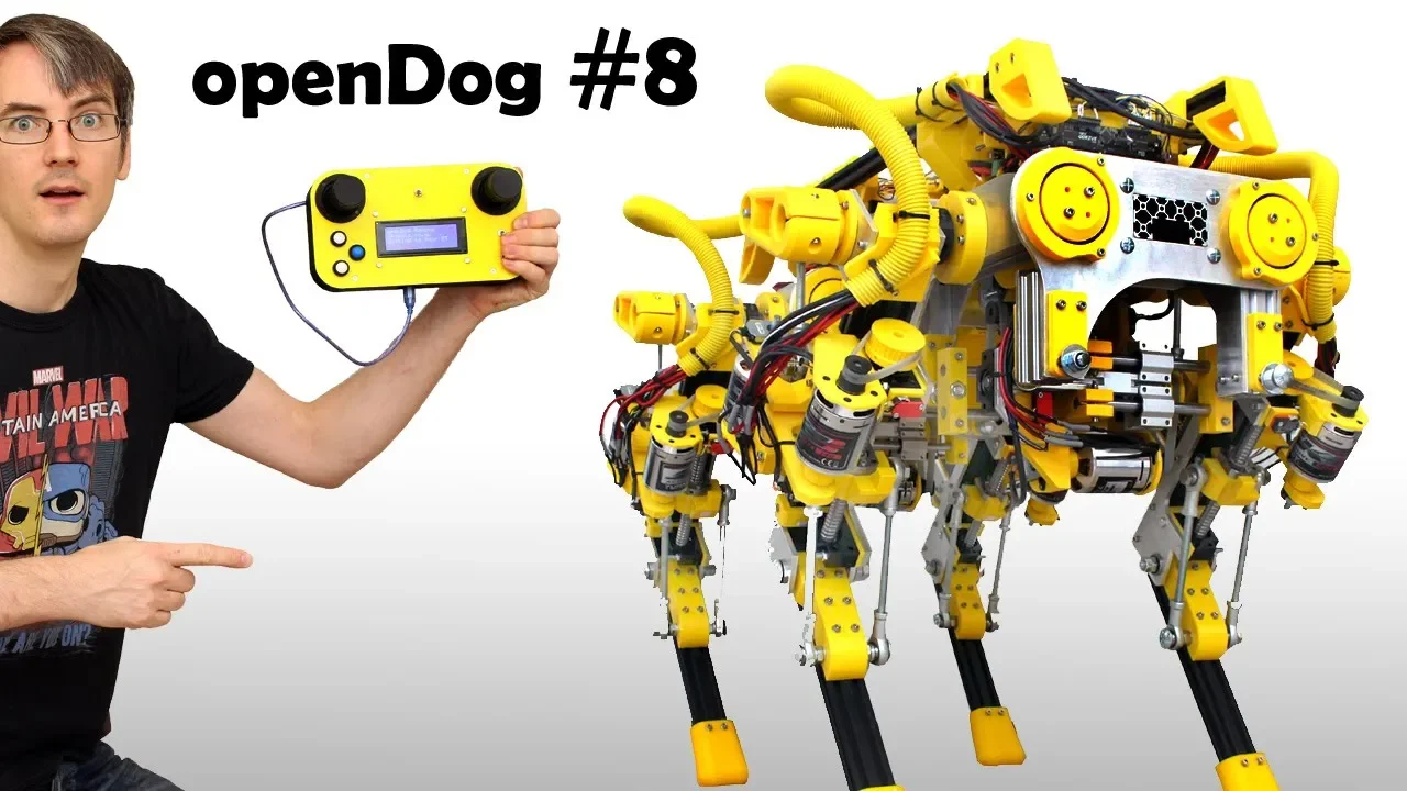
openDog Robot Leg Motor Homing and Calibration Guide
@jamesbruton
176.3K views•2018-09-11

MathWorks Virtual RoboSub Simulation Environment | Webinar 2026
@RoboNationInc
209 views•2026-03-10

Designing a Ball Balancing Robot: HAL 9000 Build, Mechanics, and Control Systems
@jamesbruton
194.7K views•2020-06-16

Micromouse: The Fastest Maze-Solving Robots on Earth
@veritasium
23.5M views•2023-05-24
Related Study Plans & Knowledge Roadmaps
Structured learning paths in Robotics