

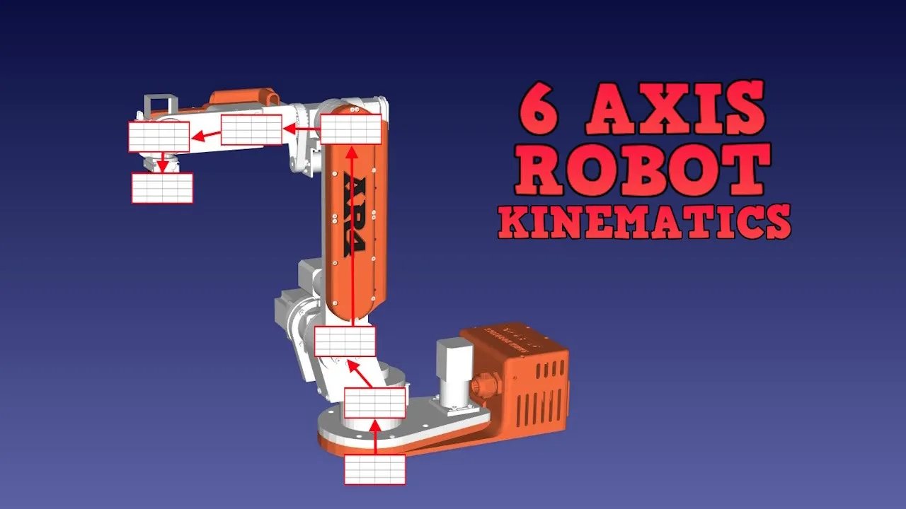














Inverse kinematics is a mathematical method that calculates the joint angles (shoulder and knee) required to position a robot's foot at specific X, Y, Z coordinates in space. The process involves using trigonometric functions and the Pythagorean theorem to work backwards from the desired foot position to determine the necessary joint configurations, enabling the robot to move its legs in three axes of translation (up/down, left/right, forward/backward) and three axes of rotation (pitch, roll, yaw) while maintaining proper leg length and joint constraints.
OpenDog V2: Kinematic Model and Walking Control Implementation
Added:Fundamentals of Forward and Inverse Kinematics (FK/IK) for multi-jointed robotic limbs.
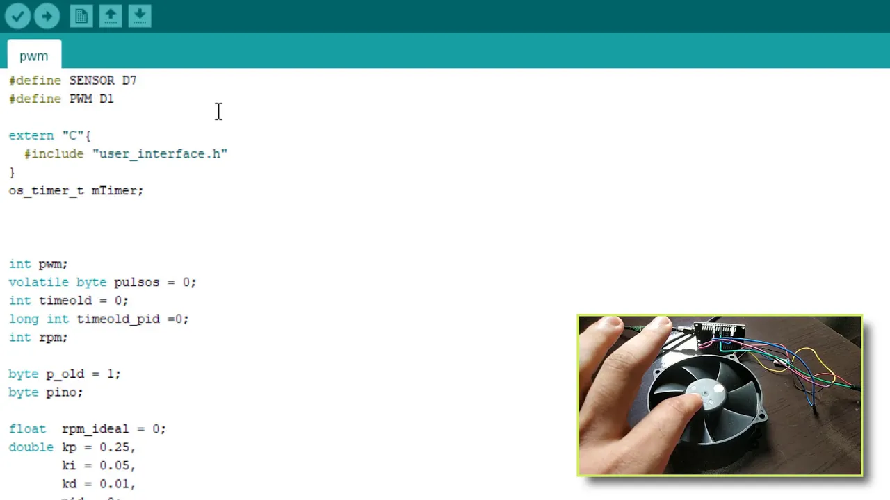
Basic control theory concepts, including PID controllers, motor calibration, and PWM signal generation.
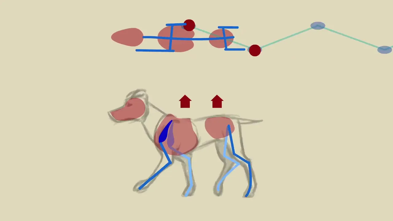
Core principles of legged locomotion, such as static stability, Center of Mass (CoM), and basic gait phases.
Embedded systems programming for microcontrollers to interface with actuator drivers and remote control receivers.
Dynamic stability and balance control using Inertial Measurement Units (IMUs) and active compliance.
Advanced gait optimization techniques, including Model Predictive Control (MPC) for dynamic trotting and running.
State estimation algorithms, such as Extended Kalman Filters (EKF), fusing IMU and leg odometry data.
Autonomous navigation and path planning by integrating ROS (Robot Operating System) with LiDAR or depth cameras.
117.5K views5.4Klikes24:09Original Release: 2020-07-28
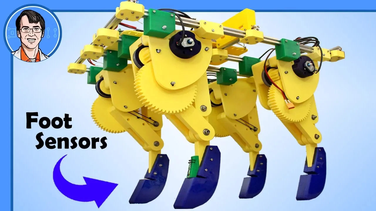
hello this is open dog version 2 part 6. don't forget to check out the early episodes in the series for the explanation about the concept and in fact all of the episodes are quite important because it shows the entire build design process and putting all the hardware and electronics together and i'm not going to recap that this time last time we had it doing jumping and we were testing the hardware capabilities but it looks like it's pretty agile and it's going to work okay so this time we're going to go back and do all that coding i haven't done so far getting the remote control working and also doing the kinematic model this video is sponsored by kiwico more on that later one of the first things i need to do is get a remote control working so i can control this without having it attached to a computer over usb and last time i was just sending commands over the serial terminal from the arduino ide to try and make this jump and do various things that's not really practical with a trailing cable so we are going to use my normal remote which is the remote i use on all the projects last time in one of the videos i talked about using rods to control robots and building a remote with a raspberry pi in that's actually connected over wi-fi we're not quite ready for that with this robot so we're gonna use the remote i use for everything and this remote is just an arduino mega it's got an nrf24l01 radio module hanging around in there and on the top here we've just got two three axis joysticks some toggle switches and one of these lcds with an i squared c backpack although all it does is just display a message saying everything remote and it doesn't actually display any other data the original plan was to have telemetry coming back so we can display useful things but i've had some issues getting the radio modules to transmit and receive quickly because when you switch from one mode to the other there is a delay which is non-trivial but before we see how the remote connection works it's time for a quick ad from the video sponsor and that is kiwiko kiwico creates super cool hands-on projects which are also totally on topic for steam education that's science technology engineering art and maths these are a great resource for learning at home but they're also super fun and although they have kid-friendly instructions they're actually great for all ages each box contains everything you need for that month's project so you don't have to go and buy anything yourself as well as the instructions there's also an educational magazine included in each project which tells you more about the topic kiwi co offers eight subscription lines for different ages and topics and each monthly crate has been tested by experts as well as by kids kiwico also has a store where you can buy individual projects and value packs that cater for all ages and you can buy items from the store without a subscription i've got three kiwico crates here one of these is a walking robot so let's open it up and have a look at the parts in detail yep that's the one right in the box we've got some instructions which have got this great blueprint design on them the extra magazine which is all about the topic of robotics and we've also got the box of parts which are all packed in individual bags on one side of our blueprint we've got the summary of the project and on the other side we've got the full and very detailed instructions we've got some stamped out parts here we've got a cardboard piece that folds up to make the body of the robot as well as these laser-cut wood pieces for its feet there's also a sticker sheet and some playing pieces and some pre-colored parts for the robot but it looks like you could color it in to make your own custom robot also included are these mechanical parts including some foam parts some plastic parts a wooden dowel some sticky pads and of course the motor and the battery and the battery holder for this project so as you can see kiwi crates really offer the perfect way to combat summer brain drain by offering fun and engaging and educational concepts that really spark interest in steam education topics kiwico's practical projects offer a great balance with screen time overload so kids can do hands-on projects and they can create make and build and most importantly be inspired so check out kiwico.com james brewton for 20 off everything and that's 20 off both subscription crates and one-off purchases so basically everything in the store that's kiwico.com jamesbruton right let's have a look at this robot remote so here's the electronics cage in the top of the dog we've got tnc 4.1 the mpu-6050 inertial measurement unit and now we've got the nrf24l01 so that's the receiver to receive data from the remote we've also got this audio capacitor i should point out which i specifically bought was a high grade fairly high value a 2200 microfarad capacitor and that's sat there so that we can smooth out that 3.3 volt rail i am using the microcontroller regulator that's on board to get 3.3 volts to power the nrf24l01 so it should be pretty good because it's a genuine tnc but they do suffer for bad power supplies have got a big capacitor there to make sure the power supply is lovely and smooth now you'll notice i've also got this additional led strip which currently has one green led on it and that's an indicator to say which mode we're in so if we plug in the remote we should see that that green led goes off and that tells us the remote is connected and on my remote i've got these buttons here which act like a menu so if i push up on this button you should see some of those leds going red in the background and they're actually counting up in binary and the select button selects the mode and you should see some other leds coming on so we'll have a closer look at that now so in mode zero all the leds are off of course mode one is a one bit mode two that's two and then two and one is three so that's binary for three then we've got four and so on and if we press the select button it basically confirms the mode so this is basically scrolling through modes if we press select then it tells you you're in that mode and it does that by mirroring the leds on the other end of the strip so again i can come up here and that should mirror the led there so that's at mode eight and then it mirrors eight if we go back to seven then that tells us we're in that mode and these modes are going to be for different functions initializing the motors and various different gates now it's time to talk about the motor initialization process so i'm using six o drive brushless motor drivers there's three in the front and three in the back each one of those drives two brushless motors and we've got 12 motors in the dog in total which is three in each of the four legs now the o drive needs to know the motor stator position so it can energize the motors properly because they're brushless motors which are three phase and these energize the coils in the right order to turn the motor properly so there's an encoder on each motor and typically the o drive will use that and it'll do a motor calibration by turning the motor each way and looking at the encoder position so it can work out what the offset is between the encoder and the motor stator position and it can drive the motors properly now in development firmware for the o drive there's the ability to use an absolute position encoder do the calibration once and then basically you can just turn the motor on and it works without having to do the calibration i'm not really keen on development firmware though i'd rather a few other people have some problems and work out the bugs so when that goes into production i will probably use it and i do have the as5047 absolute positioning code is fitted so what i was doing last time was basically just putting the legs straight powering everything on that o drive then thinks that's the zero position does the motor calibration moving the motors in each direction which takes quite some time because there's 12 motors to get through then it powers them up at that zero position which will manually align but that's not particularly reliable because i had to do it by eye and doing those 12 motor calibrations takes quite some time so what i am doing now is using the z index pulse of the encoders which occurs once per revolution i'm doing the calibration so that we calibrate to that position and then the o drive knows what the offset is from that motor encode account to the motor stator position you can find these details on the o drive website in the documentation and then from there that's the zero position and then we can move to a known position so basically on power up we always know where a fixed position is and we can calibrate from there so we can then set that up and it's much quicker to actually power the motors up instead of having to wait for that calibration turning the motor in either direction the o drives are capable of moving the leg to the z index on power up and then powering the motor up when it gets there and then it knows the offset of course once we've done that calibration on all of them which has to be done once with the o drive tool however what i've found of course is i've only got a five to one reduction so some of my z indexes are in really awkward positions and i don't really want the leg moving all the way to get there so what i've actually found i can do is actually power on the o drives move the legs manually through the whole range of motion then i can just go straight into closed loop control so that's literally all that happens in the code it's just telling the o drives to power on provided i've moved to the zed index at least once then they power on fine so a bit of a tip there so the power on process now looks like moving all the legs a little bit so we hit the z index we'll just do that and we'll do this then we go on to menu option one which should power up these the hips in fact and it should move them to their z-index and so they should all have holding power now and if we then go into the next mode it should power up the upper legs which are all of these so those have got holding power and the next mode is all of the knees so those are now all powered up fine and of course we could do this in one button press but i just like checking that it's done it because the motors are quite fast and powerful if they do anything unpredictable it's not that great if we go to the next mode it should move them all to the default position and that should be 90 degrees at the knee and 45 at the shoulder and that's where we're going to start off programming the kinematic model and these are all default o drive parameters at the moment so they're fairly sloppy the next mode up actually turns up the gains on the o drive to give much better holding power so those are much stiffer now and now we're ready to program the kinematic model what we're going to calculate and program is an inverse kinematic model and that will allow the feet to be positioned in x y z coordinates in space where z is straight up y is across the robot this way and x's across the robot back to front basically so that means we can position the feet in any of those coordinates and it will work back the joint positions which of course aren't traveling in straight lines they're rather more complicated so of course to move the foot this way means it has to get longer here shorter in the middle and longer again here so it reaches the ground still and the same front to back so we have to work back all those joints based on the xyz coordinates and we can do that with some inverse trigonometry and some pythagoras theorem now i've covered this quite a lot of times before both in open dog version one there's at least two videos on it and again with the mini dog robots at least twice there so basically that kinematic model is pretty much the same for this robot if you refer back to those videos there's more detail but i'm going to summarize it in this video the first thing we're going to do is use our leg length as the input from our z stick which is going to be the right hand twist stick we're going to give that as an input to our formula and we want to work back the knee and the shoulder angle and that's not too difficult to do because we know what all of the sides of the triangle are because we know that these are both 200 millimeters because they're fixed because those are part of the mechanics of the dog we know what this one is because that's our input so it's easy to use some pythagoras theorem and one trigonometry function to work out all of the angles of course these two are the same length which means these two sharp angles are the same and the knee is different and all those angles add up to 180 degrees so that helps us as well so we can write that in code and then when we twist that right hand twist stick to specify our leg length we should find the robot goes up and down and it's quite important here that the foot stays directly under the shoulder so it goes straight up and down in the z axis but that was only one axis out of six the next one is going to be actually moving the foot along the ground here back to front whilst keeping the shoulder at the same height and of course that leg has to get longer as it moves away from the center point and that would be the same if it moved forwards as well so now our input is this which is going to be the front to back stick that moves the dog front to backwards in hopefully a perfectly straight plane we've still got this z as our input which is the actual height of the shoulder from the ground and the output is now going to be the leg length which we pass on to the previous stage where our z input was the leg length we can just pass that onto the bit of code we just wrote before and we also need to get the shoulder angle out because we need to add that to the shoulder angle we calculated before so that whole straight line moves around and of course we can now deal with the leg that's just one length because we already calculated those previously in shoulder positions so this is a right angle triangle so it's pretty easy maths just use some trigonometry to work out that angle based on these other sides so now you should see those legs go forward and backwards in a perfectly straight line and you should see those knees adjusting most of the work is done by the shoulder of course but if we make the leg longer we should find that still works as well or shorter and then we need to do that again with our side to side axis moving the foot this way and of course it gets longer again as it moves away from that center position what i cunningly did with the build here was made sure my foot was positioned directly under the shoulder rather than being directly under the leg because otherwise we'd have to work out another weird offset triangle and add that on so the math is much easier doing it this way and of course we can reposition that foot to give it a wider stride once we've actually calculated this and the kinematic model is working so this is just another right angle triangle this is now our z height this is our new input for the side to side stick and the output that we want which will actually be this or wherever the leg is positioned will get passed on to the previous stage and the mass from that gets passed on to the first stage and that's how those numbers get passed from stage to stage so all those controls work together that's the side to side motion and again those legs get slightly longer as they go away from the center point and now those axis all mixed together so now we can move in all of those three axis and we always get our z height from the grounds and the other axis work accordingly and everything mixes together now we've written our three axis of translation which live on my right hand joystick and they allow the feet to be positioned in coordinates which run in straight lines directly up and down left and right and front to back it's now time to move on and ride the other three axis of rotation and those are going to live on my left hand joystick and those are pitch roll and your that allow the dog to be rotated around in those three axis but we want all six axis to mix and work together so the best thing to do is write a piece of math that sits in front of the translation which is written the rotation in terms of translation so basically reading those three axis of rotation the output from the maths being how to move the feet in x y and z coordinates to achieve rotation and i've covered this several times before with the previous dogs and there's lots of lovely diagrams and explanation in those videos so don't forget to check out mini dog part 4 and open dog parts 9 through 11 for the original open dog and it's explained fairly well in there but for now i'm just going to show you that it's all working so we now have the pitch axis that will pitch the robot backwards and forwards and i've limited this to 10 degrees for now and i've done the same with roll and that should roll the robot directly down the middle of the body between the two leg hip pivots we also have your that rotates the body this way again that's limited to 10 degrees and all of these work together and of course i can move the robot down in zed and i still find that those should work or i can move up in zed and they should all work as well the kinematic model runs for each leg and in the kinematic model code at the end it says if you're this leg then drive these o drives and that drives the relevant axis so actually running that kinematic model four times per loop one for each leg and now we've got those kinematic positions we can use that to make a simple walking gate and that's basically the style of walking which is a sequence of fixed positions in cartesian coordinates on timers and for now we're just going to do the most rudimentary simple type of walk which is fixed timers taking its legs off the ground and back down again and using the axis of translation and rotation to move the feet on the ground in one direction and the ones off the ground in the opposite direction and swap them over so it takes steps so there's no stability and there's no measuring of force or using the imu or anything like that to keep it stable all those keeping it stable as it's springing us in the legs and remember there's no actual springs in this it's just motor holding power but we can get it to walk i've got two bits of footage they're both shot at the same time from two different camera angles so i'm going to play them both one after the other there are some issues and we'll come back and discuss that afterwards [Music] so [Music] [Music] i'm pretty happy with that for the just most rudimentary gate using fixed timers and fixed positions of the legs to try and make it walk along and what i'm doing is using the stick here the translation stick for forward and backwards and left and right translation and the your twist stick on the left there to make it rotate and that's it i'm not using the pitch and roll axis but we could use those in the future this way you see boston dynamics use the pitch to pull back when it's got his head arm that pulls the door open or something like that but for now we're just using those three axis for the rudimentary motions to move it around and you'll notice that it's very very quick which we pretty much knew anyway from the jumping demo we did last time there's only 100 milliseconds between motion so 100 milliseconds to pick its legs up and 100 milliseconds to put them down again which means it takes five steps a second and the reason for that is that we haven't got an interpolation engine yet to slow those joints down so what we will have is the ability to visit all the waypoints from one position to the next and do that over a set period of time so we can make much slower motions that's what we did with the mini dog project where i wrote a variable speed interpolation engine that could actually change the speed of a motion once it was in progress whether we need to do that with this i don't think we do because even with no interpolation it just sorts itself out because of the natural springiness which we get from the motor holding power you'll notice there are some issues though you see sometimes it does this kind of weird gallop and that's where the feet get stuck on the ground and that's because i've done too many motions at once and it's got unstable or i've tried to take steps that are too big particularly in your and particularly in the translation sideways axis because then it's really relying on those hip motors and those really don't hold it very well it's quite wobbly so if we try and move them too far too quick and of course we've got to get the whole motion within that 200 millisecond window of the feet coming up and down then basically we get lots of wobble in the robot but it's really good it sorts itself out and eventually just recovers and carries on as it was so i guess it's a bit like jumping on a pogo stick with all the legs eventually it's just going to balance upright so i'm pretty happy with that but basically the rest of this series is going to be about making it work better than that but i'm not too unhappy so far so there are several caveats to this project i'm going to publish all the canon code and the link is in the description to this video it's all on github is an open source project and so far i haven't published anything but now it walks i'm actually going to publish everything the code to date and all of the cad in a solid model format called step or stp which means you can modify it and if you're going to build this i highly suggest you do modify it there's several issues i'm having at the moment one of those is that the knee motors get really hot and they're melting the plastic and now they're tipping over very slightly where they've melted into the pla which is causing the belts to go loose and sometimes those slip and i have to undo it all and put them back the other one is that the belt slip on the hip motions and that's because basically those motors will never double brace so again there's quite a lot of flex in them the shoulder ones never slip and those are the ones i put the bearing in the end and a bit of six mil steel to hold it so those are fine they do get quite warm but even mounted on pla they're okay so the knee motors i'm probably going to put an aluminium shim in with that acts like a heat sink and also helps brace it and it might have fans blowing on it as well to keep them cool ultimately i'm still limited to 20 amps we could go to 40 but they just get twice as hot even though we get twice as much torque the other thing is of course it is quite wobbly and that's due to the five to one reduction so probably at some point i'm gonna do another version and try and get nearer 9 to 10 to 1 reduction with a double stage reduction or something i haven't decided yet but for now we're going to taste projects as far as we can hopefully see if it will walk better and do lots of other stuff with it so if you'd like to support me on patreon or for youtube channel membership those links are in the description alright that's all for now [Music] you
Up Next
11:09
Build an Open-Source 3D-Printed Robot with ESP32 and FreeRTOS
@LHM000
824 views•2026-01-15

58:25
MathWorks Virtual RoboSub Simulation Environment | Webinar 2026
@RoboNationInc
209 views•2026-03-10

13:24
Designing a Ball Balancing Robot: HAL 9000 Build, Mechanics, and Control Systems
@jamesbruton
194.7K views•2020-06-16

25:22
Micromouse: The Fastest Maze-Solving Robots on Earth
@veritasium
23.5M views•2023-05-24
Related Study Plans & Knowledge Roadmaps
Structured learning paths in Robotics
robotics
Building Delta Robots: Kinematics & Pico
01Foundations of Delta Robots & Mechanical Design
02Electronics and Microcontroller Setup with Pi Pico
03Delta Robot Kinematics and Coordinate Math
+ 3 more learning modules
65h6 modules
Explore Roadmap
robotics
Building Ballbots: Dynamics, Kalman & LQR
01Embedded Electronics & Omniwheel Actuation
02Ballbot Kinematics & Rigid Body Dynamics
03IMU Sensors & Kalman Filter State Estimation
+ 2 more learning modules
42h5 modules
Explore Roadmap
robotics
Micromouse: Hardware, PID Control & Flood-Fill
01Electronics & Teensy Microcontroller Basics
02Sensors and Actuators: Motors, Encoders & IR
03Precision Movement: Implementing PID Control
+ 2 more learning modules
35h5 modules
Explore Roadmap
robotics
CDPR: Kinematics, Arduino & Winch Control
01Foundations of Arduino & Basic Electronics
02Stepper Motors and Winch Mechanics
03Kinematics of 2D Cable-Driven Robots
+ 2 more learning modules
28h5 modules
Explore Roadmap