









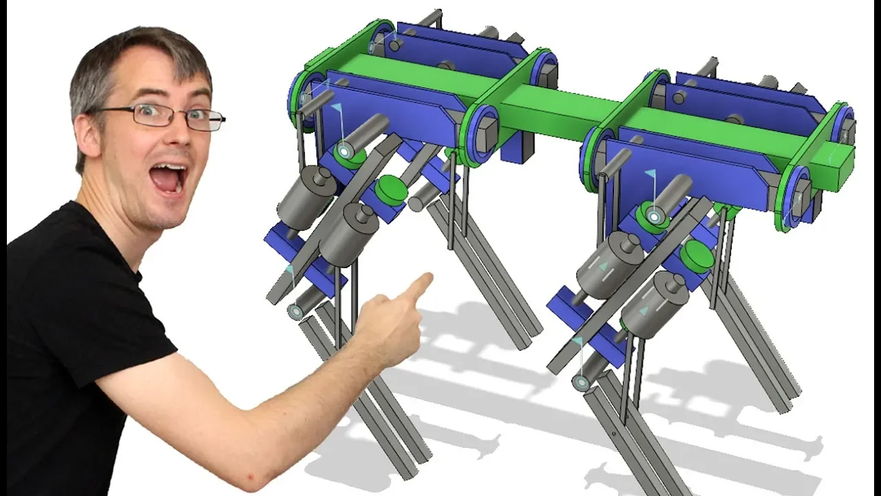



![[memmows] Walking robot navigation and state estimation](https://i.ytimg.com/vi_webp/Rqfnq6uZvK8/maxresdefault.webp)
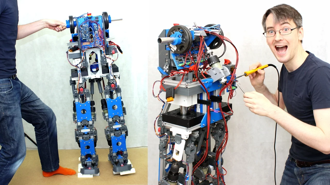

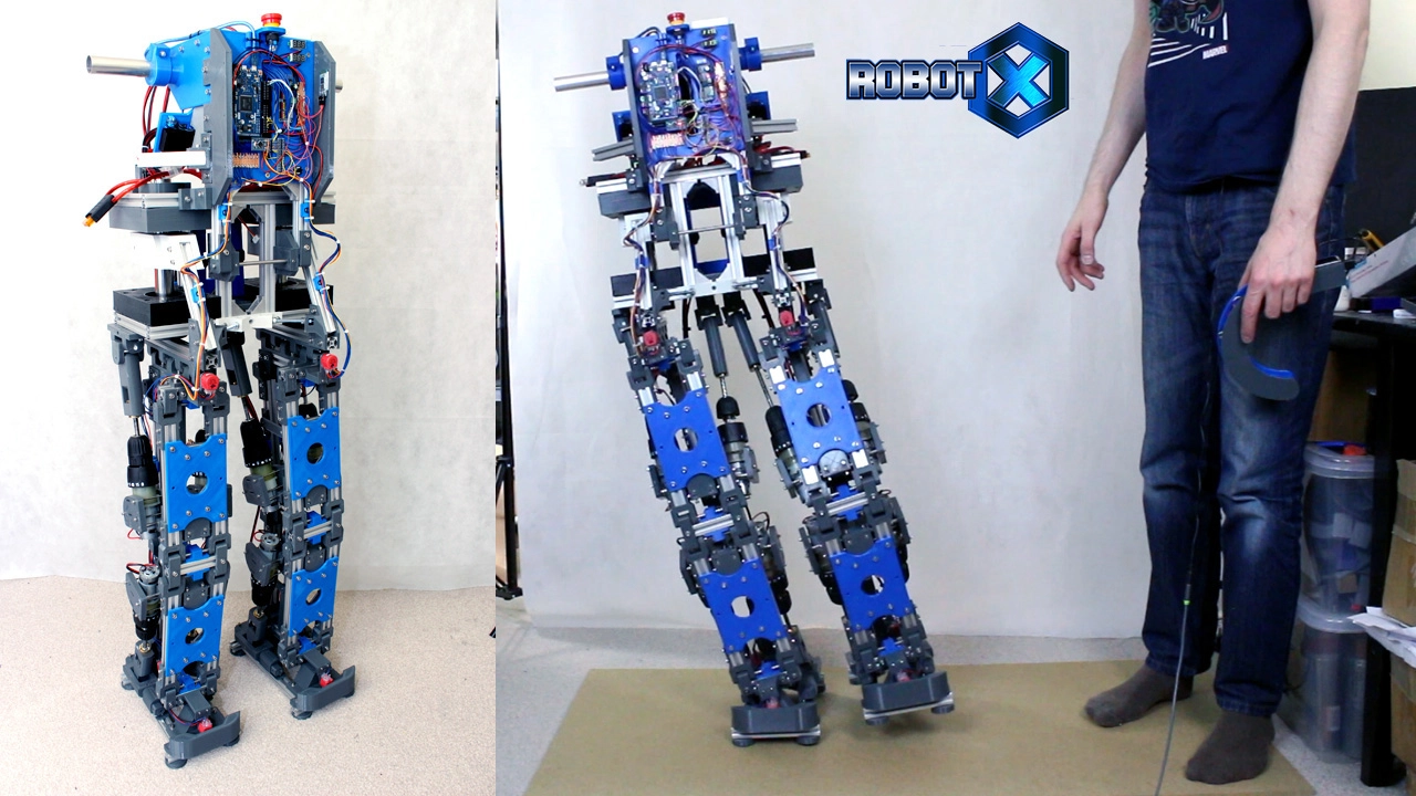



This video demonstrates the essential calibration and homing process for a four-legged robot using ODrive brushless motor controllers, covering three critical steps: setting brake resistance for regenerative braking, configuring motor magnet pole pairs for proper brushless motor control, and calibrating motor stator position against encoder feedback. The process involves using home switches to establish known positions for each joint, with the system performing motor calibration by spinning the motor in both directions to find the encoder's Z-index, then backing off a precise distance to establish a reference position. This calibration must be performed on startup since the ODrive needs to know the exact relationship between motor stator position and encoder counts to properly energize motor coils at the correct times for brushless motor operation.
openDog Robot Leg Motor Homing and Calibration Guide
Added:hello its James here is part 8 of open dog the open source dog robot as you can see we've done quite a lot already on this there's obviously seven videos already building and prototyping all of the mechanics putting the electronics in which we did last time and this time we can actually write some code on the robot at least for the initial setup to get all those motors and encoders homes and kill those actuators in the right position so we can eventually build the kinematic model and then we can control all of those joints the only thing I've done since last time is built this wooden support frame to hold the robot up so I can mess around calibrating the legs without it falling over and that's got four posts and it holds the robot up on the actual posts which are part of the stationary part of the robot of course one side of the mechanism moves the other one is stationary and those are offset so we've got them in sort of diagonal configuration those four posts hold them up there so if I should hold the robot nice and stable so we can mess around with the legs so before we can make the robot move we need to do three things on the Oh Dr calibration we need to set the brake resistance or regenerative braking on each Oh Dr we also need to set the number of motor magnet poles for each of those twelve motors so the o drive can control the brushes motors properly and we also need to set the motor stator versus in code a position so that that calibration doesn't have to run on every powerup basically we'll run it once and then we'll hard-code those values and then these encoders have Zed indexes on them which means on the powerup the motor will just rotate to find its dead index and we'll know exactly where it is my robot has six o drives and each one controls two motors each o drive is supplied with a brake resistor so these old drives will do regenerative braking which means that basically when the motor is braking it will put power back into the battery to recharge it which is quite good if you're using a mains power supply of course you don't have full power back into it I'm using batteries so I'm setting my brake resistance to zero however we need to check we never overcharge the batteries are currently there's two one on each side that will eventually be six in total so what we're going to do is just not charge those fully so that we can push some power back into them to keep them charged when there's braking on the motors and we won't overcharge the lipo's so brushes motors are a bit special they have three wires and three phases and you have to energize each phase exactly the right time depending on the motor stator position so he can push the magnets rounds now some motors have Hall effect sensors in and the motor drive will read those to work out what the position is so you can sync everything up some of the cheap RC brushless motor drivers don't have any sensing but they use the back EMF that comes back off the motor coil to work out all the motor position is and in our case of course we've got encoders and those encoders are not only used for that motor magnet positioning the motor stator positioning so you can energize the coils at the right time they're also use for counting the position of the motor and keeping track of it I'm using the O Drive tool to configure the O drives and that just plugs in with a USB cable and allows you to configure the parameters so I've set the motor breaking resistance to zero they look like the motor pole pairs value is already correct and I'm not going to go into too many details about the O Drive tool because it's probably subject to change it's changed completely since the early episodes I did with the early R&D on the prototype leg and the O drive so have a look at the o drive website the documentation is really good and complete and you can get hold of that tool as well on github so let's talk about that motor calibration the motor stator calibration against the encoder calibration so if we don't hard-code the offset then the startup looks like this so the motor goes beep and then it should turn in one direction you should stop and turn back the other way and that allows the o drive to calibrate the motor stator position against the encoder the encoders got eight thousand one hundred and ninety two counts per revolution so it's really high resolution if we were to hard-code it then it doesn't need to do that anymore all it needs to do is see kids in position which occurs once per revolution so on startup we just say to calibrate the motor it would just turn a little bit and that would be it now I've got a few issues here because I've got the encoders attached as you can see to a piece of eight mil studing shoved into a piece of plastic attached to the back of the motor that's what causes the encoder to move when the motor moves now the motors are actually provided with a metal piece which is what you'd normally put on the back of these motors for drones and that's a proper aluminium nice machined piece that goes on the back there and ideally that's what I've used to put the encoder on however this has got a ten mil shaft on it and the maximum hole in the encoder is basically an adapter for eight mil so that's why I haven't used these ideally I turn these down in the which I will do eventually when I get a life I don't have one at the moment so I've got this makeshift piece the only slight challenge is the 8 mil studying slightly smaller than 8 mil so I don't think the encoder is gripping properly and some of them have slipped and I've had to wrap tape around them to make the shaft bigger so that doesn't seem very reliable for now I've also got a 3d printed plastic please eventually I'd like to upgrade them I think they might slip against the shaft and although it doesn't affect the encoder in order to do so I have to kind of slacken the whole motor off to get the belt on so this is OK for now but it's not the best solution and we really do need to keep that encoder in sync with the motor später if we hard code it any deviation is going to call for motor not to operate properly so for those reasons I'm going to manually run the full calibration on each start up and we can call that from code until I've replaced those pieces with metal and I'm sure that the encoder is tied to the motor reliably so now it's finally time to make the legs work and I could just drive the motors but we need to put a home switch on which I fitted last time but I didn't put on anything to press it so now I've got these blocks which you're going to fit on here and as this whines towards the end of the axis of course it'll switch the switch and that's also going to be right at the hard end stop so far over run them the motor jams and it doesn't break the switch off so we need to set up a homing routine which we discussed last time with the illuminated buttons on the control panel which would be to home each leg in sequence and then once they're all homes then we can actually give them proper position data so why not use absolute position feedback encoders on the actual joints instead of home switches well we could do that but it would only be any use when we first powered the robot on to discover what the state of the robot was what the leg position was because basically the O drives still need that encoder coupled to the actual motor in order that they can energize the motor coils properly and use the brushes motor properly and though what the stator position is of the motor so we still need those encoders couple to the motor attached to the O Drive so that the Oh Dr can drive the brushless motors so for now and in switch will do so we can get to a known position for that joint we could put absolute position feedback on the joints in the future but it has to be really accurate and it's only gonna function when we first power it out the same as the end switch does so now I've modified my control panel code so instead of the lights just chasing each one as you press them onto the next slides basically now when you press this one it goes out until homes which gets pressed and first it looks for the home switch zero which is that one for motor 0 and then it looks for the other one so I'll press that and then you can see the next light comes on and then if we press that it looks for the home switch over the other side to be pressed on low to zero on that o drive and it looks for the next one which is around the other side and then it will go on to do the actuators underneath but we're probably going to boot the legs up and take the wooden stand out before we go and do those and obviously we need to do both ends of the robots as well and the code for that part's pretty simple so essentially it's looking for button presses and this is a state machine using this statement so it's got a flag set to zero so the first time you press it the flag is 0 it does some bunch of stuff here which is basically a while loop looking for that home switch to be pressed another while loop looking for the next home switch to be pressed obviously I need to put in the stuff to actually move and stop the motors and then is increments the flag to one and that goes on to the other leg with the other buttons and eventually all do the actuators underneath I haven't done anything for those yet so now I've put the belt on so the actual motor can drive the thing that pushes the end switch so if we press the first button on the control panel we should see the first motor calibrate there we go so it's gonna spin one way and then the other way which doesn't take too much longer than just looking for the Z position so we're pretty happy with that for now the next thing it does after the calibration is goes and presses the switch and then it's thoughts that switch position as a variable and it backs off exactly two revolutions and that means we've got a known position for the leg and you can hear the other one beeping so now it's doing the exactly the same on that one there it goes so you should see that homing on its switch and backing off exactly two revolutions so now those joint two in a known position and we know the encoder offset so you may just be able to see that the next light is come along the control panel if we press that one it does the other side of the robot so should start homing this motor and doing exactly the same thing my control panels divided into two halves of course this is the one end of the robot and this is the other end of the robot and of course those are controlled by two different slave arduino z' so this one's now ready to do the actuators underneath we'll come to later and the other one is still waiting for me to do the first actuator this end as you'd imagine is exactly the same so if I press this button it starts behind this one and then it goes through doing this side and then goes to the other side once it's done so of course I've added in the O drive stuff to the code so we've got to the Oh Dr library being used here we're using both of the ODE drives here on the to UART serial ports we will have a third one for the undercarriage actuators that will be on a software serial but for now they're on both you aren't serial so we've got two Oh Dr objects called Oh Dr one and O drive two in set up we set up the current limit which is currently set to 10 amps and we set the velocity limit there to 1,100 so that's pretty slow and pretty low-power we can turn that right up to 70 when the time comes and that does two of them for each of the O drives it connected to the two you want serial ports once we press the first button we need to do the motor calibration so put it into the motor calibration state then it looks for the offset calibration and then it puts into closed-loop control mode that means we can control it and it's got holding talk now if we had hard-coded the motor stator position versus a Zed index we could scrap this one and just do a Zed encoder index search so a little bit quicker there's only one line of code we need to change once we've done that calibration in the future the only thing I did change was about the home switches so we've now got this filter here so I found because I'd use unscreened cable I had quite a lot of phantom home limits which presses so basically what it does is resets the clock if the homes which is one which is when it's not pressed because their input pull up and when it's zero it checks that the time has expired which i think is about 50 milliseconds at the moment and that filters out any jitter on those lines it's a bit nasty really I should have used screened cable but this seems to work perfectly well so after that of course it sets the velocity on the motor to 10,000 and then when the home switch is pressed we're using a while loop to monitor that switch it goes off and stops the motor does a 300 millisecond delay then this code here is for basically reading the offset position from the encoder released reading the encoder position and then we do a set position using the include accounts and we do that for two revolutions so it's using the offset position and then taking away eight 192 include accounts forever illusion times two and that means it actually backs off to revolutions and then it goes on of course says that it's gonna do the next motor some of this comes out to the serial terminal for debug and does the other axis and does that four times for the four motors so now the legs have all found their known positions I've written an extra bit of code that turns both orange lights on that's before it gets to the white lights and if I press them it should lift the whole robot off the stand so it can definitely lift itself and it's still on hardly any power that holding torque is still on about 10 amps and lifts itself perfectly well we can go right up to 70 amps and 48 volts instead of 24 volts and I'm not even running full speed they're nowhere near it's about 20 times slower than the top speed I've had on about 30 amps and 24 volts so it's just enough to get it off the stand only just though you'll notice you can do going a bit higher really anyway now we can lift up each leg individually and go and bring them into the limit switch which actually brings them in which is why I've removed the stands then we can deal with homing those actuators so this is still actually running just on one battery at the moment now I've got a clamp meter here which measures up to 100 amps DC there's AC and DC and all you do is put this round the cable tells you how much currency is being drawn so I don't have to do it like that it's upside down but what we've got there is so point four - so 400 milliamps if I turn one motor yeah that goes up to about one and a half and if I let go again it goes back to 400 milliamps and that's just holding power basically for eight motors so it's not really drawing much power at the moment so I'm using the bike on the camera now instead of the title it might because the cable from that picks up all the Moton always like a big Ariel so now we're now ready for the next stage of the homing so basically what we're gonna do is pick up this leg and then go and home it with the actuators that live under here so first of all I'm going to stick a piece of wood in because it can't stand on three legs any more than your dining room table can obviously if it's moving slowly I'll have to lean over in order to pick up its feet and if it's going fast I'm not sure what happened we've Roybal eggs we found we could just pump the feet really fast we didn't really have to pragmatically leave math side to side it stayed up okay so I'm hoping this will be the same four legs so next I just press the control panel button that's now gone white and it should pick this leg up as you can see then you hear the beep and that's the motor calibrating so you should be to see this motor turning there it goes and then you should bring the actuator in till it hits it's how you switch which is off of this end and then it puts you back a set distance again and then it brings the link down again there we go and so we can see the wood down out and we can do the other side as well it's not too bad just to hold up I just hold it here do the same thing to this side that's picking the leg up then we should see the other motor turning and calibrating and moving in to hit the home switch which is off of the other end on the actuator and moving out a known distance and putting the foot back down on the grounds so you're into the robots exactly the same as that it's exactly the same code running the other slave Arduino to control that Oh Drive so I'm not gonna bother going through the code is pretty much the same as the leg homing it's doing exactly the same thing just with different switches and addressing a different o drive but the code is on github if you really want to go through it so the next thing we need to do is control those two slave arduino z' from the master arduino so that we can control the whole robot in one go and control all twelve motors so let's think about what we actually need to do so far we've got a transmitter with some joysticks on here and this was used for testing in the early episodes check back on those to see this in action actually controlling one leg that's got a Bluetooth transmitter in and that sends data to the master Arduino that sits in here now master Arduino is it eventually going to calculate the kinematic model so it's going to take these joystick motions for the six axis and turn that into X Y Zed motions for the legs and we can do that in the next video then we've got two more Arduino to act to slaves those are the ones we've been putting code on in this episode and they actually control 2o drives so what we need to do is build a comms model that sends data from the master Arduino to the two slaves essentially there's a serial relays the send that joint position on and actually control the motors so this is the code that's currently running on the master Arduino inside the dog there so basically we're using build Porter's Easy Transfer library and that's the send data from the remote to the master Arduino and eventually we'll use our same library to send the data onto the slave arduino z' basically we've got the LCD there on both the remote and the dog so i'm using the liquid crystal library and this is all the setup for that now the easy transfer library involves declaring data sets we've got one for receiving from the remote so this is all the menu buttons and this is the sticks and we've got one freshies sending data back so of course we're sending data back to the display the remote like acts like a dumb terminal so the mode is actually being set on the code that we're looking at now which is running on the dog and the the receiver there is just getting that data and displaying it so it's tracked on the dog it's also displaying a count every time the code loop goes around so we can see that the code is running and that is also displayed on the dog as well just for completeness essentially so we've declared these data sets with names we can read so the send data and the remote data and we're running the code loop every 20 milliseconds so that's what this piece of code does here so we've got our count adding up on every code loop and that's being put out to the display on the dog and of course it's actually sending that data back to the remote as well this is to do with the menu tracking for those modes so adds one sort of mode every time I press one particular switch and takes one away when I press the other one and at the moment we're just writing out that serial data for the sticks to the screen and not doing anything more with it so if we open a serial monitor we can see that we've basically got the six pieces of data there the first one being the right stick for the left right action the right stick for the front-to-back action and the right stick for the twist action so each of these joysticks is six axis and the other side is exactly the same so the next thing to do would be to write the kinematic model which will sit in here taking those stick positions that piece is going to happen next time but for now we're just going to budge some numbers and write another set of easy transfer data sets that send that data on to the slave arduino z' so the first thing we're going to do is make a data set on the master arduino and that's going to send that data onto the two slaves so now when our master arduino we set up two more objects called et3 and et4 remember the first two are for sending receiving to the remote control and of course one of these is for the first slave and one is for the other for the front and back of the robot we've also set up two data structures slave one and slave two and I'm calling the joint access hip and hip for each side of the robot which is the actuator that moves the legs underneath the robot the under carriage and then shoulder and elbow which are the actual joints on the leg I would call it like sort of another hip and a knee but basically they point in the right way for shoulders and elbows so that's the easiest way to remember and have given those easy names to remember my data back and my date of front which is again for the back and front of the robot we then attach those to the serial ports on that one slave Arduino serial one and serial three and remember that that Arduino mega has four serial ports a numbered 0 through 3 and these are the actual wires that attach to the 2 slave Arduino for the front and for the back so right at the bottom of the code are transmitting data sets I'm transmitting the 2 right shoulders and the 2 left shoulders and no other access at the moment and actually taking the remote data the right hand twist stick and I'm scaling that from 0 to 1023 because it's 10 bit analog to digital converter - in fact - 50 - 50 I'm doing that for all of the axes and - 50 - 50 s actually the length in millimeters which is sort of not quite the maximum travel but pretty much the travel for testing at least of that actuator and I'm not going for submillimeter accuracy this is gonna transmit integers but we are doing something on the other ends that will give a submillimetre travel we then doing 83 and 84 send data that transmits that data to the two slaves so now we're sending that data from the master on two different serial ports and we're going to receive that on the two slaves so now we're on the first slave Arduino that controls the back of the robot and both of them are very similar of course it's practically identical code so defined another data structure for easy transfer which has got those same access in it and when we need to me that identical so that we can receive exactly the same data and this one has a slave data structure called my data back because it's the back of the robot we're then attaching that data structure to the first serial ports and this is the same on both slaves because they both have serial one free now as a test I'm doing this right at the top of the code right at the top of the main loop here and we're doing an e t3 receive data which is receiving that data set and basically we're going to write out both values to the screen which are the shoulder left and right and I'm also doing some filtering so if you remember in part 3 of the series I did a filter the smooth out those values and makes them really nice so if we scroll to the bottom we can see we've now got a function that basically does some smoothing so check out three to see how that works and what the results are but basically if we open a serial plotter here we should be to see a nice graph getting plotted and if I twist the stick here now both the values are the same so you can't see very much the both overlaid on each other for both shoulders of course because it's the same value from the same stick but you can see my stick value that's minus 52 plus 50 in green and you can see my nice red value there which is nice and smooth and that's the actual value that we're going to give to the actuator so remember data comes from the remote control those thick's positions the six axes and all of the buttons and that's sent via bluetooth over to the master arduino we're going to run the kinematic model on there that calculates all the leg trigonometry calculating all the angles back to actuator lengths we're skipping that out for this time but for now I'm just patching some numbers through to the two slave arduino x' that actually drive the two Oh Dr x' [Laughter] so it's a few funny sounds there the main sound you can hear is the 3d printed pulleys and the belts running on them because they're not quite aligned I think actually here the end stops on one of those demos but also the conduit maybe makes a sound or there's something clicking there somewhere might be that but it is also the first time it's actually moved its legs fully since I've assembled it so I guess there's still a few things that are settling in there's possibly some creaking between plastic and metal bits and need tightening up and what have to go and sort all that out as we go and activate the other axes as well so the code for that looks like this we get to the end of the homing where we've put the leg straight after homing the undercarriage axes and then we set the flag in the state machines of five so the next part only happens once the complete calibration is complete and all the homing is complete if obviously the Arduino loses power we have to go back and do the calibration again anyway so this will only happen once that calibration is definitely complete on each powerup so the first thing we do is receive the data and of course this only happens once the homies complete because that's the only situation under which the flag is set to five this is the same code that I showed before receiving that data I'm still typing out to the serial terminal for dye eggs taking that filtered value and we're then multiplying the filtered value by a number of include accounts per revolution to get the millimeters to turn into encode accounts and that takes into account the gear ratio from the motor to the ball screw which is about 2.1 for something and then we're making a home value and that home value is using the value that the leg axis moved to get to its arbitrary middle position as making a new home taking into account the offset as well and that's called home to home and home for home so we then use those values plus or minus the stick value in millimeters now in encode accounts which is then centered around zero so that actually makes the offset and causes the actuator to move so basically once the homing is complete the leg should stay in exactly the same home position until we wiggle that stick and then it moves it plus and minus and all of this code is pretty temporary once we've done the kinematic model will actually have the correct amount in millimeters to get to the joint angle and then that will be the final solution so eventually we'll set some strengths on each ball screw using that home position so they can't run their end stops and obviously that will count the encoder clicks the O Drive knows where where this is exactly so if we just put in code never to go past a certain position then that will be fine and the O Drive will never hear its end stops so of course on each powerup the two slave arduino z' need to use that control panel they need to do the homing sequence to get all of those home positions and calibrate the motors but once it's powered up that's it I can then reboot this one the master arduino multiple times as I build the kinematic model and experiment with gates and so on without having to recalibrate these every time because of course these will keep power and they don't need to be rebooted so that means I can just keep flashing the master arduino and i don't have to do the calibration every time I change the code so as I've said some of that code is temporary particularly on the slave Arduino and of course the master doesn't have a kinematic model yet I am putting the code on github as I go because it is a truly open source project the Caddy's up and from last time the complete assembly so if you want to build one of these and I don't recommend you do yet you can and you can also sell them or modify it and sell them as long as you publish the source all right so that's all for this time don't forget these projects are funded through patreon so have a look at patreon.com slash x robots and you can get access to some exclusive rewards including a livestream with me and my videos early alright that's all for now [Music]
Up Next

RatSLAM: Biologically Inspired Robot Mapping and Navigation
@milfordrobotics
20.9K views•2012-08-03

MathWorks Virtual RoboSub Simulation Environment | Webinar 2026
@RoboNationInc
209 views•2026-03-10

Designing a Ball Balancing Robot: HAL 9000 Build, Mechanics, and Control Systems
@jamesbruton
194.7K views•2020-06-16

Micromouse: The Fastest Maze-Solving Robots on Earth
@veritasium
23.5M views•2023-05-24
Related Study Plans & Knowledge Roadmaps
Structured learning paths in Robotics