Building AGVs: QR Navigation & Lifter Systems
Learning Goal: Build an industrial-style AGV (Automated Guided Vehicle) that navigates a grid layout using a downward-facing camera for QR code landmark localization and a lifter mechanism.
Estimated Total Study Time: 32 hours
Module 1: Introduction to AGVs & Embedded Electronics
This module provides a comprehensive foundation for understanding how industrial automated guided vehicles operate in modern factories. You will master the physics of differential drive kinematics and study the hardware configuration of high-power DC motor drivers and microcontrollers needed to move heavy physical payloads.
Recommended Videos
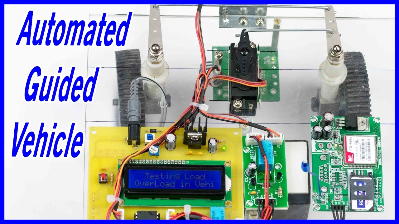
Why this video is valuable: This video serves as the perfect system-level introduction to custom AGV design. It demonstrates how autonomous mobile platforms coordinate microcontrollers, safety sensors (such as ultrasonic sensors), and localized feedback tools to transport loads across a warehouse environment.

Why this video is valuable: To build an AGV, you must understand how wheel rotation translates to translational and rotational motion. This lecture breaks down the core kinematic equations of differential drive robots, relating left and right wheel velocities (, ) to heading angle () and position ().

Why this video is valuable: Standard low-power motor drivers will burn out under the weight of an industrial AGV chassis. This tutorial covers the wiring and pinouts of the BTS7960 43A high-power H-bridge motor driver, showing you how to control large DC motors using PWM signals from a microcontroller.
Knowledge Checkpoint
- Calculate the forward velocity () and angular velocity () of a differential drive robot given the wheel radius () and individual wheel angular speeds (, ).
- Connect the BTS7960 motor driver to an Arduino or Raspberry Pi and configure the enable pins (R_EN, L_EN) and PWM pins (R_PWM, L_PWM) to achieve bidirectional speed control.
- Trace the signal path from a path-planning microcontroller to the motor driver, identifying potential noise isolation issues and power ground loop hazards.
Module 2: Chassis Design & Lifter Mechanics
AGVs must not only navigate, but also interact with physical payloads. This module guides you through the CAD design process of a mobile chassis and dives into the mechanical engineering principles of lifting mechanisms—specifically scissor lifts and linear actuator lead screws.
Recommended Videos
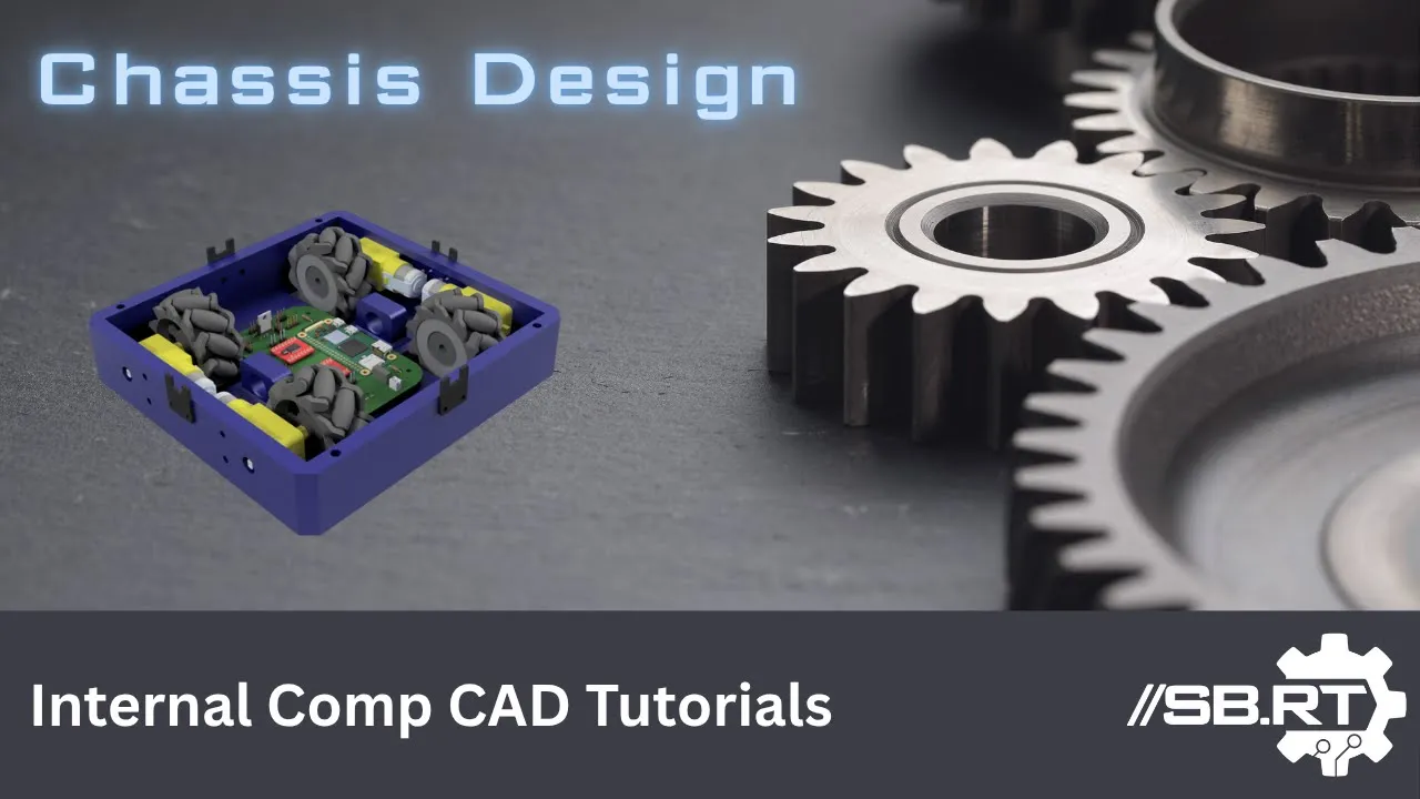
Why this video is valuable: This deep-dive Autodesk Inventor CAD tutorial provides a blueprint for structuring a mobile robot chassis. It focuses on critical physical layout techniques such as center-point modeling for stable center of gravity, physical component clearance, and robust mounting interfaces.
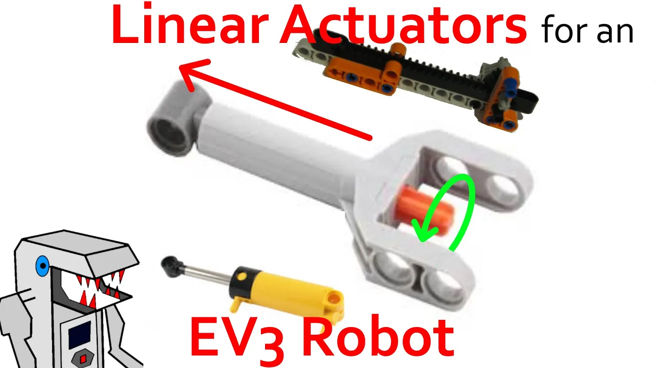
Why this video is valuable: This video introduces linear actuators and lead screw mechanisms that convert rotary motor force into vertical linear motion. It details how to select and integrate actuators based on force requirements, stroke length, and speed constraints.

Why this video is valuable: Scissor lifts are the industry standard for low-profile, high-capacity vertical lifting. This demonstration details the physical assembly of scissor linkages, showing how multiple crisscrossing stages are aligned to ensure a perfectly level payload surface throughout the lift stroke.
Physical Structural Integration Guidance
Curriculum Note: When integrating your lifting mechanism with a mobile chassis:
- Ensure the center of gravity of the payload remains directly centered between the drive wheels to prevent tipping.
- Mount the linear actuator base directly to the structural frame plates of your chassis rather than relying on thin 3D-printed paneling.
- Route all lift-mechanism power cables through dynamic cable tracks to prevent binding during compression.
Knowledge Checkpoint
- Draw a free-body diagram of a one-stage scissor lift mechanism and identify the point of maximum mechanical stress during structural extension.
- Determine when to choose a multi-start lead screw over a single-start threaded rod based on mechanical efficiency and self-locking requirements.
- Design structural brackets to mount a linear actuator to your AGV's lower chassis plates while ensuring proper clearance for the drive motors and battery packs.
Module 3: Computer Vision & QR Code Localization
This module teaches you to turn a downward-facing camera into a sub-millimeter precision localization sensor. You will master OpenCV-based QR code extraction and the geometric homography equations necessary to convert pixel coordinates into precise real-world coordinate offsets on your warehouse grid floor.
Recommended Videos

Why this video is valuable: This step-by-step tutorial shows you how to leverage OpenCV and Pyzbar in Python to read QR codes from real-time video streams. You will learn to isolate bounding box coordinates, extract decoded payload string data, and draw visual overlays.

Why this video is valuable: This lecture introduces the mathematical framework of planar homography. For a downward-facing camera tracking floor landmarks, homography maps pixel locations directly to physical coordinates on the ground plane, bypassing complex 3D perspective math.

Why this video is valuable: Downward cameras suffer from lens distortion that warps geometric measurement. Prof. Stachniss explains the industry-standard Zhang’s calibration method, demonstrating how resolving intrinsic and extrinsic camera matrices yields corrected, linear coordinate transformations when the target plane altitude is constant ().
Camera-to-Ground Homography Implementation
To transform a detected QR code corner in pixels to real-world floor offsets relative to the camera center:
Where is a Homography matrix computed during system calibration using 4 known points on your floor grid. Once is stored on the AGV's companion computer (e.g., Raspberry Pi), any QR detection yields an instant centimeter-level error offset vector () and heading error ().
Knowledge Checkpoint
- Calibrate your camera using a checkerboard pattern to find its focal length () and principal point () values.
- Write a Python script using OpenCV (
cv2.findHomography) to calculate the homography matrix mapping four pixel locations to four physical points. - Explain how lens distortion parameters () affect the coordinate accuracy of landmarks detected near the edges of your camera’s field of view.
Module 4: Grid Navigation & Motion Control Algorithms
With localization working, this module shows you how to close the feedback loop. You will program PID controllers to smoothly align the vehicle over landmarks and implement a robust Finite State Machine (FSM) to coordinate movement, alignment, and lifter activation.
Recommended Videos

Why this video is valuable: This video breaks down the mathematics behind Proportional-Integral-Derivative (PID) closed-loop control. You will learn how each term operates on your feedback error to smoothly drive the AGV's physical motors toward zero positional error without instability.

Why this video is valuable: Complex AGV operations require a formal control structure. This video provides a robust implementation guide for writing clean, maintainable state machines in Python, which is vital for scheduling sequential behaviors like path navigation and physical load engagement.
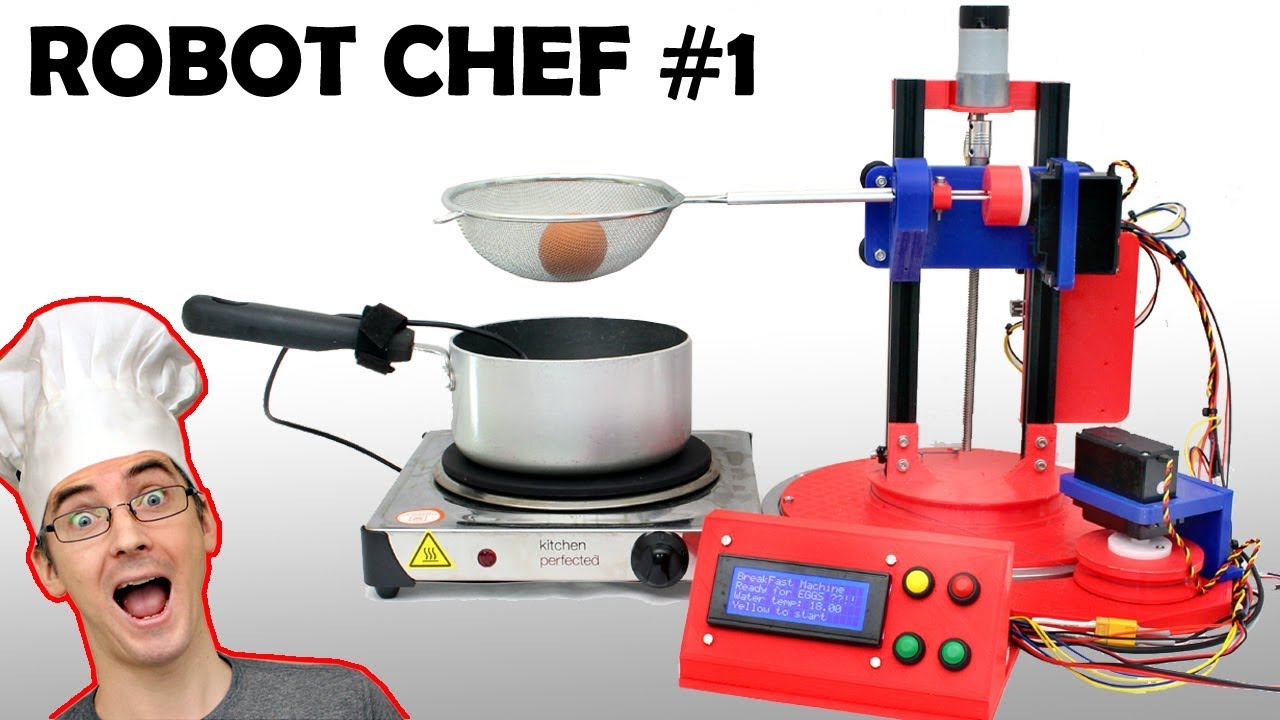
Why this video is valuable: James Bruton demonstrates a practical, state-driven robotic sequencer in action. He shows how to declare sequential states via a state variable to coordinate mechanical movements and sensor checks, providing a structural template for your AGV's behavior.
Python Finite State Machine (FSM) Template
For an AGV to coordinate traveling, landmark alignment, and lifter activation, organize your script around this standard state execution model:
class AGVStateMachine: def init(self): self.state = "IDLE" # Initial state self.target_qr = None
def spin_once(self, camera_data, odometer_data):
    if self.state == "IDLE":
        # Wait for dispatch command
        self.target_qr = self.get_next_job()
        if self.target_qr:
            self.state = "NAVIGATING_GRID"

    elif self.state == "NAVIGATING_GRID":
        # Run path-following control loop
        if camera_data.qr_detected == self.target_qr:
            self.state = "PRECISE_ALIGNMENT"
        else:
            self.send_drive_commands(self.calculate_grid_path())

    elif self.state == "PRECISE_ALIGNMENT":
        # Engage homography-based PID centering loop
        error_x, error_y, error_theta = camera_data.get_homography_offsets()
        if abs(error_x) < 0.005 and abs(error_y) < 0.005:  # 5mm tolerance
            self.stop_motors()
            self.state = "ACTIVATE_LIFTER"
        else:
            self.send_drive_commands(self.calculate_pid_velocity(error_x, error_y, error_theta))

    elif self.state == "ACTIVATE_LIFTER":
        # Trigger physical lift payload
        if self.engage_lifter_mechanism(direction="UP"):
            self.state = "IDLE"  # Action completed!
Knowledge Checkpoint
- Implement the provided Python FSM framework on your companion computer to handle state transitions from standard grid navigation to precise alignment over a landmark.
- Tune a positional PID loop's proportional gain () to achieve rapid convergence over a QR code target without causing the robot to oscillate.
- Implement windup protection limits (clamping) for the Integral term () of your position and rotation controllers.
Module 5: System Integration, Safety, & Testing
This module pulls all the mechanical, electrical, and computational components together. You will integrate LiDAR and other safety sensors, set up physical mock warehouse courses, and perform diagnostic integration tests to verify the AGV runs reliably under standard operating conditions.
Recommended Videos
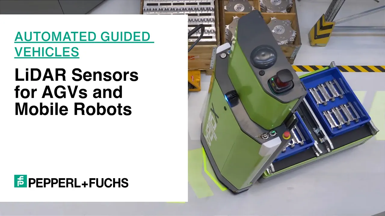
Why this video is valuable: Safety is paramount for autonomous platforms carrying heavy loads. This video details how industrial LiDAR systems establish dynamic safety fields and protective zones on AGVs, triggering deceleration and emergency stop states when obstacles enter their path.
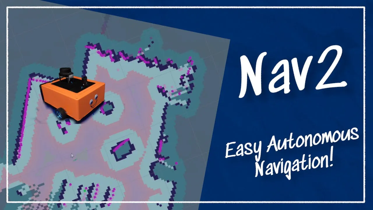
Why this video is valuable: This video serves as an integration guide, showing how hardware drivers, sensor inputs (such as LiDAR), localization algorithms, and motor controllers interface using a standard software framework (ROS). It details the process of starting and testing navigation configurations.
Safety System Field-of-View Integration
To protect operators and payloads, map your safety sensors (LiDAR/Ultrasonic) directly to override interrupts inside your motor control loop:
              +----------------------------------+
              |  LiDAR / Distance Sensors Scan   |
              +-----------------+----------------+
                                |
                Is obstacle inside Warning Zone?
                /                              \
             YES                                NO
             /                                    \
+-------------+-------------+ +----------+----------+
| Decelerate Drive Velocity | | Is obstacle inside |
| (Set maximum limit 30%) | | Emergency Zone? |
+---------------------------+ +----+-----------+----+
| |
YES NO
/
+-------------+----+ +-----+-----+
| Cut Motor Power | | Safe path |
| (Force STOP) | | Clear |
+------------------+ +-----------+
Knowledge Checkpoint
- Connect a 2D LiDAR or array of distance sensors to your companion computer and map their ranging profiles to spatial zones relative to your chassis coordinates.
- Program a hardware interrupt that immediately cuts off enable signals to the BTS7960 motor driver if an obstacle is detected within 30 centimeters of the robot.
- Conduct a diagnostic integration test: log your camera-to-ground alignment error over 20 repeated approaches to confirm positional repeatability stays within a 5-millimeter window.
Course Map
Key People Index
- Prof. Peter Corke (Professor of Robotic Vision, QUT)
- Context: Featured in Module 3. Author of the foundational textbook Robotics, Vision and Control. Corke provides the definitive mathematical proofs for planar transformations and image projective geometry.
- Prof. Cyrill Stachniss (University of Bonn)
- Context: Featured in Module 3. A world-renowned researcher in SLAM and photogrammetry. Stachniss provides highly regarded, open lectures on camera calibration algorithms and geometric sensor models.
- James Bruton (Robotics Designer & Educator)
- Context: Featured in Modules 4. Bruton is a former toy designer and electrical engineer known for physical prototyping, hardware-in-the-loop testing, and implementing accessible state machine patterns.
Final Self-Assessment
Perform this final diagnostic checklist to verify your finished AGV platform meets all core technical requirements:
- Power Safety: The power delivery network utilizes an inline fuse between the battery and the BTS7960 motor driver to protect components from overcurrent situations.
- Kinematic Control: The AGV moves forward 1.00 meter on a level floor with less than 2 centimeters of lateral drift without active sensor feedback.
- Robust Calibration: The downward-facing camera has successfully generated its camera matrix and distortion coefficients using Zhang's checkerboard method.
- Coordinate Homography: The vision pipeline detects a floor-mounted QR code and calculates physical coordinate offsets () relative to the camera's optical center.
- State Machine Management: The FSM controls state transitions from path-following navigation to precise QR alignment, then to lifter engagement without getting stuck in a loop.
- Physical Lift Performance: The vertical lift mechanism can successfully raise and support a 2-kilogram payload without binding, slipping, or drawing excessive current.
- Safety Override: The obstacle avoidance sensors (LiDAR/Ultrasonic) override active drive commands and bring the vehicle to a stop if a person or obstacle blocks its path.
- Target Repeatability: The integrated system can navigate from an idle state, locate a target QR code on the floor, align itself, lift the target payload, and move to a drop-off point autonomously.