![LAZO ABIERTO y LAZO CERRADO ✅ [Sistemas de CONTROL] #009](https://i.ytimg.com/vi_webp/CxGFoeJ7SD8/maxresdefault.webp)







![UNIT & DIMENSIONS L-3 [ BASIC MATHS ]](https://i.ytimg.com/vi/YQRyOgN2jRw/sddefault.jpg)




![ZIEGLER NICHOLS ✅ SEGUNDO Método [Control PID] Parte 2](https://i.ytimg.com/vi_webp/AAaWNNuqpuY/maxresdefault.webp)


![[제어공학 치트키] 3편. 제어공학 어렵게 공부 할 필요 없습니다.](https://i.ytimg.com/vi/fSHtYCyWT7Q/maxresdefault.jpg)







A PID (Proportional-Integral-Derivative) controller is a feedback control mechanism that calculates a manipulated output signal based on the error signal (difference between desired setpoint and actual output) using three distinct actions: proportional control (KP × error) which responds to current error, integral control (KI × ∫error dt) which eliminates steady-state error by accumulating past errors, and derivative control (KD × d(error)/dt) which predicts future error trends based on the rate of change. The controller output in s-domain is expressed as MS = [KP + (KI/S) + KD×S] × ES, where ES is the Laplace transform of the error signal. The significance of PID controllers lies in their ability to combine the advantages of all three control actions: proportional control reduces rise time, integral control eliminates steady-state error, and derivative control decreases maximum peak overshoot and settling time. The block diagram shows the controller connected in series with the plant, with unity negative feedback, and the transfer function for a second-order system is derived as C(s)/R(s) = [KD×S² + KP×S + KI] × ωn² / [S² + 2ζωn×S + KD×ωn²] × [S² + KP×ωn²/S + ...].
PID Controller Explained: Basics, Block Diagram, Transfer Function
Added:This session I'll be going to cover P controller and these are session outlines where I'll be covering total output of P controller. Then I'll explain physical understanding of P controller. Then we'll see significance of P controller. Then I'll explain log diagram of P controller. And then we'll derive transfer function of P controller. and then at the end we'll be discussing advantages of P controller.
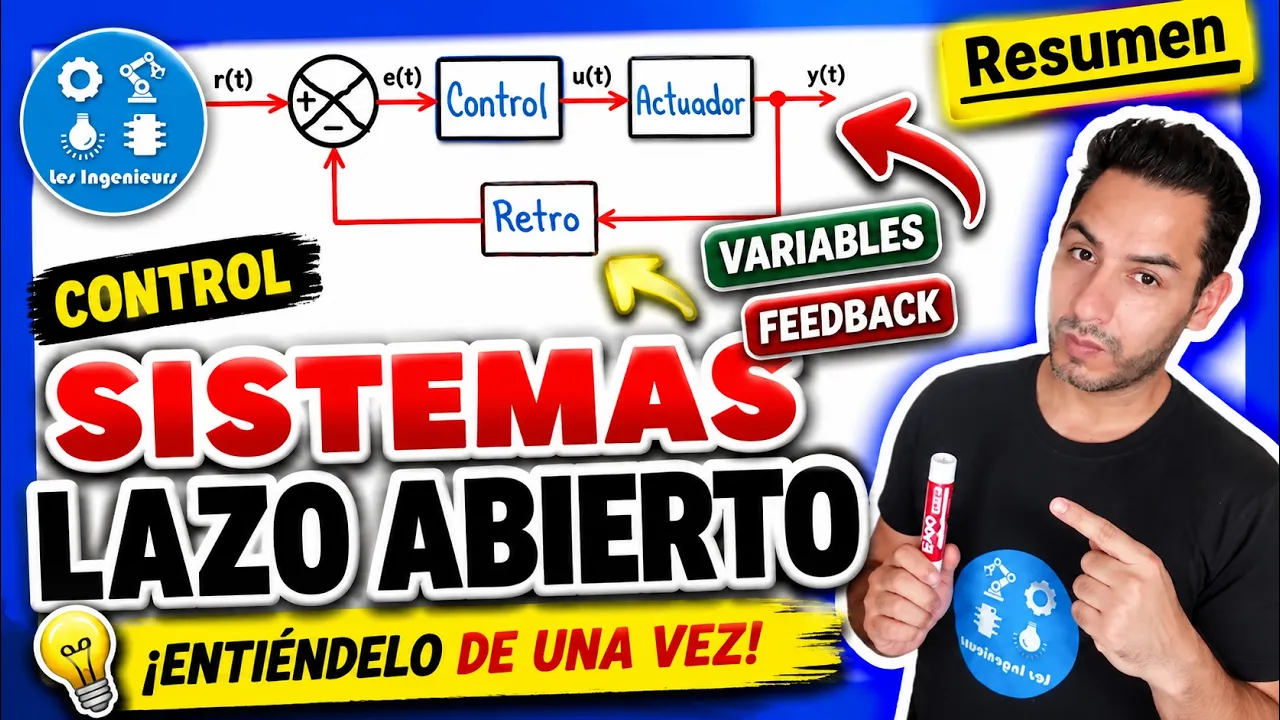
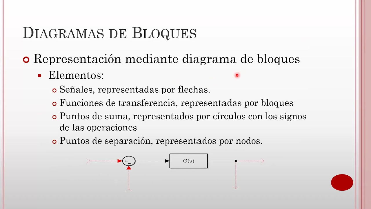
So when we talk about basic closed loop system in control system then these are the basic block diagram which is what we are having where plant is been given by controlled output by controller and output of plant that is what given in feedback. So input to controller that will be difference in between input and output and that even referred as error signal. So we give error signal as input to controller and output of controller that is even referred as manipulated signal.
So this is what the basic block diagram which is there with control system. Now out of this basic block diagram one can see what is the controller which is there in P controller. So this portion that is what we are using as P controller. When we talk about P controller, P controller is having three portions which is what we need to understand.
One is proportional control, one is integral control and one is derivative control. So here to this controller we give input that is what error signal.
So error signal in time domain it is ED.
So error signal that is what we are giving as input to controller and manipulated signal that is what controller output in time domain it is empty. So let us first calculate controller output means manipulated output in terms of time domain. So output of controller that is empty and that is addition of all these three blocks. So in KP it is multiplied with error signal ET plus in KI it is integrated by ET DT plus in KD it is differentiated D by DT.
Now to have this function in terms of S doain let us have Laras transformation.
So laplas transform will result this signal in terms of frequency domain or you can say s domain. So that is ms is equals to kp into e s plus integration that is resulting divide by s. So this will be now ki by s into es s plus differentiation that will result into multiplication of s into es now. So let us rewrite this.
So if I rewrite this then now it will be MS is equals to KP plus KI by S plus KDS into ES. So this will be the controller output.
Now let us try to understand what is the physical understanding which is there with P controller. So here one can clearly see this is error signal which is changing with respect to time. Now this error signal ET that is given to all controller proportional integral as well as derivative. So when we give this signal to proportional controller now output that will change with respect to input.
Shape of signal is not depending on any other thing than error signal only gain that is what we are multiplying with this. So this proportional controller's output that will be KP into AD. So that is what similar to ED only thing is we just multiply gain KP with error signal.
So this is what output which is there with proportional controller. Now that is what getting added with integral controller. Now integral controller's output that is purely based on positive area and negative area. So here one can clearly see this is negative area. So what will happen over here with integral controller as area is positive integral controller's output will increase and it will increase till area is positive and as area is negative now this output now from here it will start to decrease it will decrease till area is negative.
So see this is how output that is getting changed with integral controller and that is even referred as KI into integration EDT.
When we talk about derivative controllers output so derivative controller's output that is based on slope to the line. So here if I say slope over here is horizontal.
So that is zero. Over here slope is negative. Here slope is negative. Here slope is negative. Again here slope is horizontal. So zero. Here slope is positive. So based on that derivative controller's output that is zero over here. Now due to negative slopes signal will decrease. It will decrease till negative slope is there. Now after that slope is getting positive. So now signal will increase. So this is how output will change. So this is what we can say derivative output and that even we can refer as KD into D by DT of ET. So this is what derivatives output. So that is based on slope of input signal.
Now let us move on to next which is what significance of P controller. So P controller that is having significance of proportional controller, integral controller and derivative controller. So all those benefits which is there with P that is based on proportional, integral and derivative.
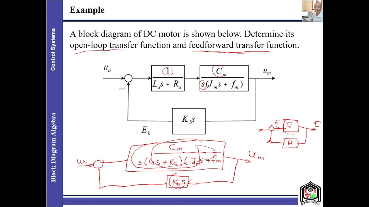
To understand it already I have placed three videos based on proportional integral and derivative. So you just watch out few of my last videos where you will be getting what are the significance which is there with P proportional integral and derivative. So I'm skipping it right now. The reason is that is what I have already discussed in last few sessions. So let us move on to next point that is what block diagram of P controller. So here one can say this is what controller block. This is what controller block and this is what system block. This is what system block. Now this controller block that is KP plus KDS plus KI by S and this is what getting multiplied with this system block and that is what we can say that is GS and HS is unity feedback which is what one and that is over here as a negative feedback.
So based on this system we'll be deriving transfer function. So let us derive transfer function of P controller with second order system.
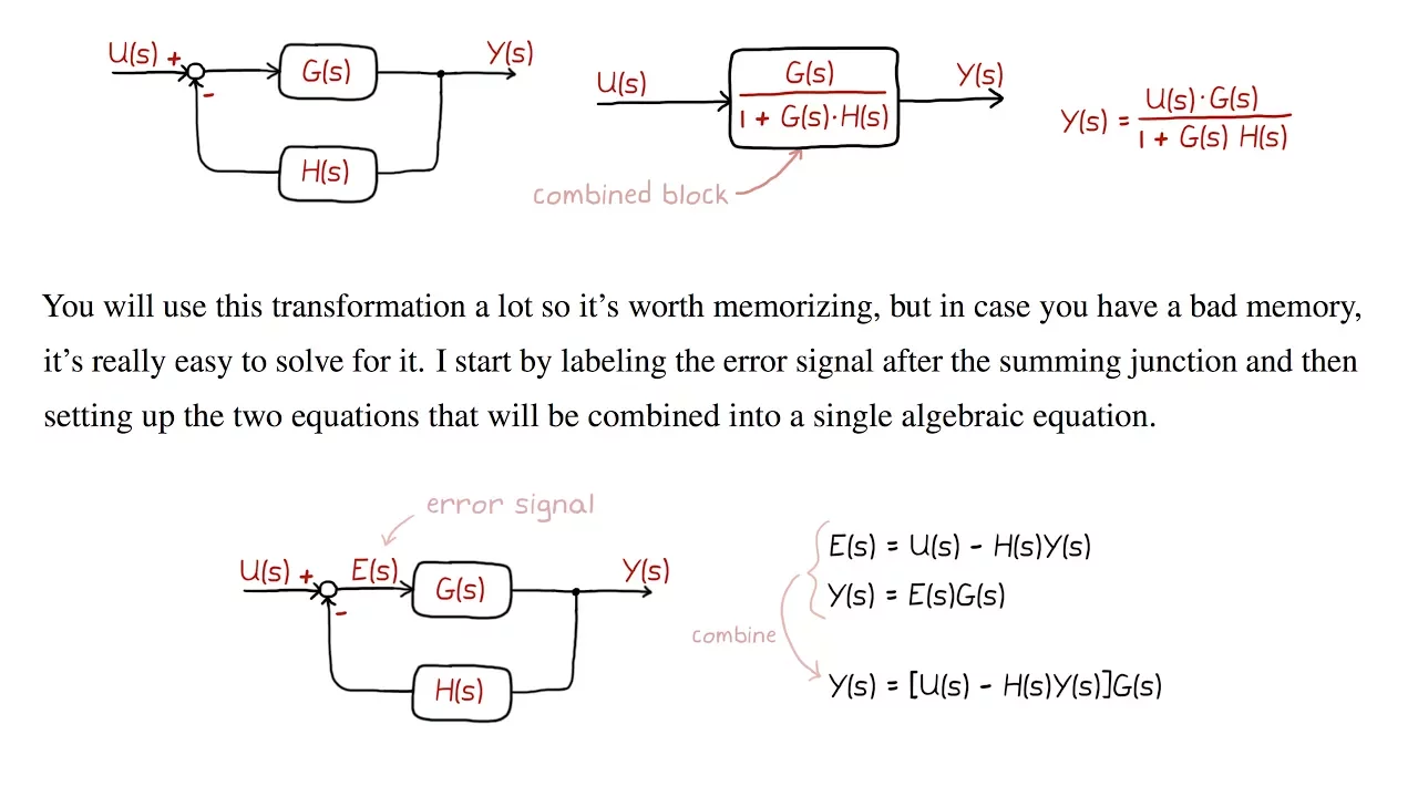
So here transfer function of this system that is CS by RS that is equals to GS / 1 + GS HS. Now here GS is KP + KD S + K I S into omega square N divid S into S + 2 Z omega N.
So this is how we have GS and HS is equals to 1. So let us place this.
So here GS is equals to KP + KDS + KI by S into omega² and divide by S into S + 2 ZA omega N and HS that is 1.
Now if I place this value into CS by RS then transfer function that will be CS by RS that is equals to KP + K D S plus K by S into omega² N / S into S + 2 ZA omega n / 1 + hs is 1. So again this will get repeated kp + k d s + k i by s into omega² n / s into s + 2 za omega n. Now if I take LCM of S as well as S into S + 2 Z omega N then this will get cancelled from numerator and denominator and transfer function will reduce to KD S² + KP S + K I this into omega² N divide I sq + 2 za omega n + k d omega n² into s² + kp omega n² into s. So this will be transfer function which is what we are having.
based on P controller.
Now what are the advantages which is there with this P controller. So there are so many advantages.
Let us discuss few based on proportional controller.
It will decrease rise time based on integral controller.
It will eliminate steady state error based on derivative controller.
it will decrease maximum peak overshoot and it will decrease settling time.
So this is how advantages of proportional integral as well as derivative that is what we are utilizing all together in P. So these are the basic advantages which is there with P controller. Thank you so much for watching this video. If you like this video then please subscribe to my channel and you will get complete series of almost every subjects which is what you are observing over here in my channel. Thank you so much for watching this
Up Next
Kalman Filter for Gyroscope and Accelerometer Angle Fusion
@carbonaeronautics
228.7K views•2022-12-30

Ultrasonic Transducers: Resonant Frequency Measurement and Horn Design
@imajeenyus42
229.9K views•2017-02-22

Polymer Environmental Degradation: Mechanisms & Stabilization
@iit
1.8K views•2012-07-10

How a Student's Question Saved a NYC Skyscraper from Collapse
@veritasium
22.8M views•2025-04-26
Related Study Plans & Knowledge Roadmaps
Structured learning paths in Engineering