The BTS7960 is a high-power motor driver module capable of driving loads up to 43A with built-in overheating and overcurrent protection, supporting bidirectional control of two DC motors or a single stepper motor; it connects to Arduino Uno through pins 2 (IN1), 3 (IN2), and 4 (PWM) for motor control, with power connections (Vcc 5V-27V and GND) and motor outputs (OUT1, OUT2) to the motor terminals.
How to Use BTS7960 Motor Driver with Arduino Uno
Added:Deep Dive
Basic Arduino programming fundamentals, including writing code, using the IDE, and managing digital/analog input and output pins.

arduino starter kit e basi della programmazione
48.5K
Arduino programming uses the Arduino IDE (free from arduino.cc). Key concepts include: (1) Pin configuration using 'int led = 12' to assign pins to variables; (2) Setup function 'void setup()' runs once at startup; (3) Pin mode configuration with 'pinMode(led, OUTPUT)' to set pins as outputs; (4) Loop function 'void loop()' runs continuously; (5) 'digitalWrite(led, HIGH/LOW)' controls digital pins; (6) 'delay(milliseconds)' creates timing delays. A complete LED blinking program requires configuring pins, turning LED on, delaying, turning off, and delaying again within the loop.
Click to watch →
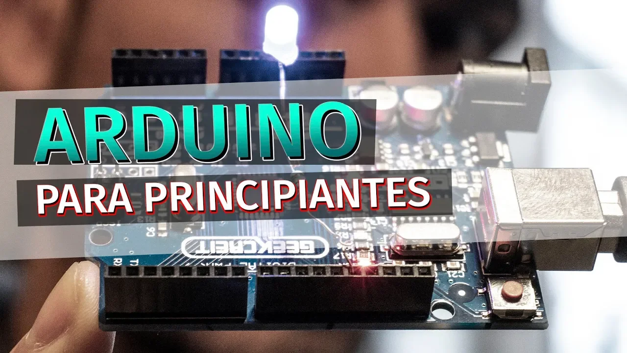
Arduino para principiantes | Instalar el IDE y comprender lo básico
340.7K
Arduino is a popular, economical electronics platform consisting of hardware (programmable boards with input/output ports) and software (Arduino IDE). The hardware is open-source, allowing users to create their own boards. The IDE runs on Windows, Mac, and Linux. Arduino uses a simplified C/C++ programming language, making it accessible to beginners. Applications include weather stations, automatic lighting systems, and various projects. To use Arduino, download the IDE from the official website and install it. The IDE provides access to code examples, documentation, and project ideas. Arduino programs consist of two main functions: void setup() (runs once at startup for configuration) and void loop() (runs continuously for main functionality). The Blink example demonstrates fundamental programming concepts including pinMode() for pin configuration, digitalWrite() for controlling outputs, and delay() for timing control.
Click to watch →
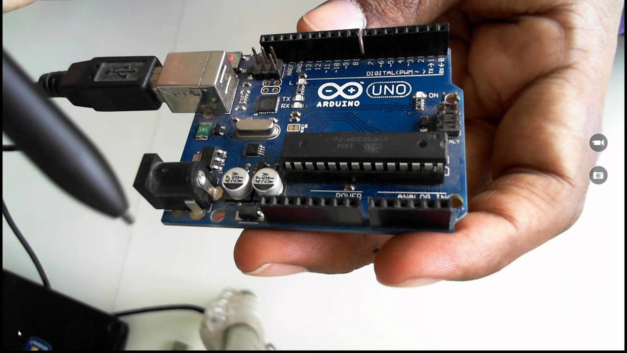
Beginning with Internet of Things IoT for Developers
171.5K
Arduino programming uses C-based sketches written in a simplified version of C. The Arduino IDE provides tools for writing, compiling, and uploading code to the board. The IDE includes a Serial Monitor for viewing output. Arduino programs have only two main constructs: setup() (runs once at startup) and loop() (runs continuously). Built-in functions include pinMode() for configuring pins as input or output, digitalWrite() for writing values to digital pins, and delay() for introducing time delays in milliseconds. Libraries are pre-written code that simplifies working with sensors and components, handling complex communication protocols and data interpretation.
Click to watch →

2- التعرف على الأردوينو | Introduction to Arduino
3.3K
Arduino programming uses a C/C++-based language called Arduino language, with programs called 'sketches' written in the Arduino IDE. The IDE interface includes a title bar, menu bar, toolbar, and code editing area with default code. The Setup section runs once at startup for configuration (like setting pin modes), while the Loop section runs continuously in a repeating cycle for main program logic. Pin configuration uses pinMode(pinNumber, MODE) where MODE is INPUT or OUTPUT. Pins 0-1 are reserved for serial communication.
Click to watch →

Cum să începi cu Arduino? pinMode, digitalWrite, delay
21.4K
This comprehensive section covers the complete Arduino programming foundation for beginners. It includes: (1) Hardware requirements: Arduino board, USB cable, computer, and Arduino IDE software (version 1.3.12 supports Windows, Mac, and Linux); (2) Verifying board recognition and selecting the correct COM port; (3) Understanding Arduino program structure with setup() for one-time initialization and loop() for continuous execution; (4) Configuring pins as INPUT or OUTPUT using pinMode(pinNumber, MODE); (5) Controlling outputs with digitalWrite(pinNumber, HIGH/LOW) where HIGH sends 5V/3.3V and LOW sends 0V; (6) The importance of consulting Arduino documentation for proper syntax and understanding function parameters. The instructor emphasizes that programming is creative and flexible, with the same functionality achievable through different code approaches.
Click to watch →
Deep Dive
The concept of Pulse Width Modulation (PWM) and how it is used to control motor speed and duty cycle.

PWM Configuration, Programming and Simulation | LPC2148 Course
6.5K
PWM (Pulse Width Modulation) is a technique used to control motor speed by varying the duty cycle. The duty cycle represents the ratio of on-time to total time period in a PWM signal. Higher duty cycles result in faster motor speeds, while lower duty cycles produce slower speeds. This method is commonly used in DC motor speed controllers and allows for precise control of motor performance by adjusting the average voltage delivered to the motor.
Click to watch →

PWM(Pulse Width Modulation)제어란?
89.4K
PWM controls motor speed by rapidly switching the power supply on and off at high frequencies. The average voltage delivered to the motor depends on the duty cycle—the ratio of on-time to total cycle time. For example, with a 1-second on and 1-second off cycle, the average voltage is 5V (half of 10V). By adjusting the on/off timing ratio, the effective average voltage—and thus motor speed—can be precisely controlled while maintaining full voltage capability during the on periods.
Click to watch →

Kỹ thuật Vi xử lý - Ôn tập
3.7K
Pulse Width Modulation (PWM) controls motor speed by varying the duty cycle (ratio of on-time to total period). Higher duty cycles produce higher average voltage and faster motor speeds. For example, 0% duty cycle stops the motor, 50% provides half maximum speed, and 100% provides full speed. The duty cycle is typically set once and maintained until changed, making it more efficient to configure PWM in a dedicated function rather than repeatedly in the main loop.
Click to watch →

Tech Garage Episode 2309
102
Pulse width modulation (PWM) is a method of controlling motor speed by sending pulses of voltage rather than continuous voltage. The computer controls how long the voltage is on versus off. More pulses (higher duty cycle) means the motor spins faster, while fewer pulses (lower duty cycle) means slower speed. This is the modern replacement for resistor-based speed control.
Click to watch →

April 7, 2021 - Embedded Software Design, Model-Based Embedded S/W, Auto-code Generation.
331
PWM controls motor speed by rapidly turning power on and off at fixed frequencies. Unlike linear voltage control which wastes energy and limits speed range, PWM maintains full voltage during on-cycles. The average voltage depends on duty cycle—the ratio of on-time to total period. A 50% duty cycle delivers half the maximum voltage. This technique provides efficient, proportional control with full speed range from 0% to 100%.
Click to watch →
Deep Dive
The basic operation and circuitry of an H-bridge, which allows DC motors to run forwards and backwards.

Como funciona uma Ponte H Conceitos Básicos #1
6.9K
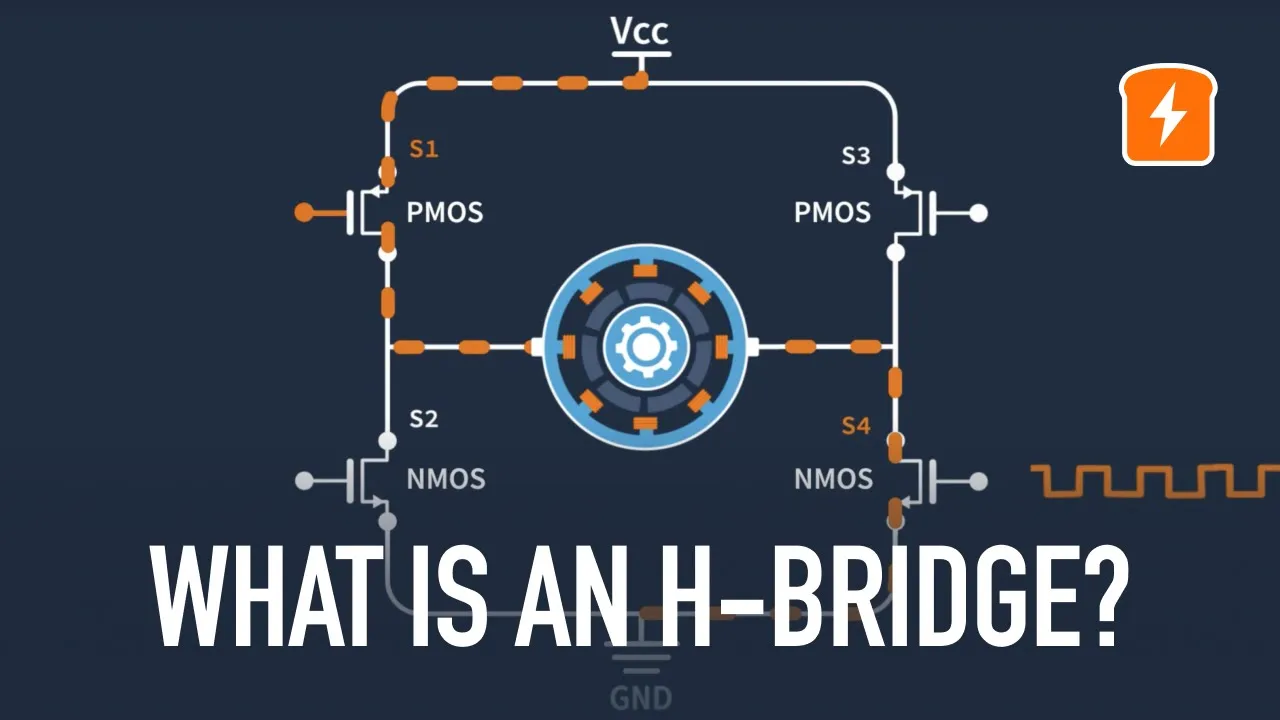
An H-bridge is an electronic circuit that controls the direction of a DC motor by reversing the polarity of the power supply; it uses four switches (S1, S2, S3, S4) arranged in an H-shape, where closing S1 and S4 connects the motor to the positive and negative terminals for one direction, while closing S2 and S3 reverses the polarity for the opposite direction, with the center position disconnecting the motor to stop it.
Click to watch →
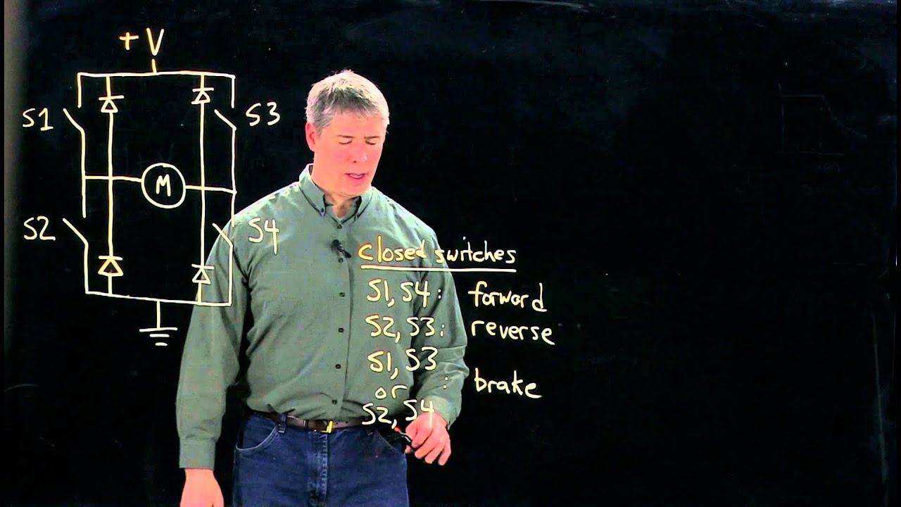
Driving DC motors, part 3/3: H-bridges (Kevin Lynch)
32.7K
An H-bridge uses four switches and four flyback diodes to control DC motor direction and braking; by selectively closing different switch pairs (S1+S4 for forward, S2+S3 for reverse, S1+S3 or S2+S4 for brake mode, and open switches for coast/freewheeling), the circuit can drive the motor in either direction, apply dynamic braking to slow it down, or let it freewheel without applied voltage.
Click to watch →
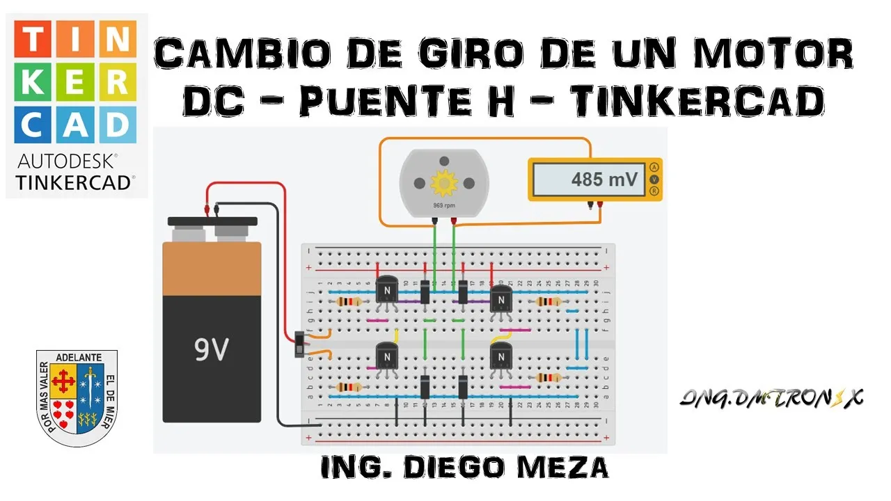
Cambio de Giro de un Motor DC - Puente H - TINKERCAD
19.3K
An H-bridge circuit uses four transistors (2N2222) to control DC motor direction. When transistors Q1 and Q4 activate, voltage flows through the motor in one direction (forward rotation). When Q2 and Q3 activate, the voltage path reverses, causing reverse rotation. Diodes prevent parasitic currents during switching. The circuit requires a complete closed loop with power supply, transistors, and motor. Understanding transistor pin configuration (base, emitter, collector) and diode polarity is essential for proper circuit operation.
Click to watch →

Ponte H para Motores DC
2.8K
An H-Bridge is an electronic circuit that reverses the direction of rotation of DC motors. It is specifically designed for DC motors and cannot be used with AC motors. The circuit is named for its resemblance to the letter 'H' and consists of four switches (S1, S2, S3, S4) arranged in a bridge configuration. The positive voltage enters from the top, and the motor is connected in the middle. Closing different combinations of switches determines the direction of current flow through the motor: closing S1 and S4 produces forward rotation, while closing S2 and S3 produces reverse rotation. In practical implementations, mechanical switches are replaced with transistors (NPN and PNP types), where NPN transistors should have their emitters connected to ground and PNP transistors to positive voltage for reliable operation.
Click to watch →
What is an H-Bridge?
63.4K
An H-bridge is an electronic circuit topology consisting of four switches arranged in an H-shape that enables bidirectional control of DC motor rotation by switching the polarity of voltage applied to the motor terminals; it can operate in four main states—forward rotation (switches 1 and 4 closed), reverse rotation (switches 2 and 3 closed), coasting (all switches open), and braking (both ground or both VCC switches closed)—with speed control achieved through PWM signals when using MOSFETs instead of mechanical switches, though designers must avoid shoot-through conditions where opposing switches conduct simultaneously.
Click to watch →
Deep Dive
Fundamental electronics safety rules, particularly the separation of logic-level power (Arduino 5V) from high-current motor power supplies.

DC Motor Control with an H-Bridge and Arduino (Lesson #17)
164.1K
The logic level voltage pin (pin 16 on the L293D) connects to the Arduino's 5V output, providing power for the internal control circuitry. This is distinct from the motor power connection (pin 8), which connects to the external battery. Maintaining isolation between these two power domains prevents damage to the Arduino and ensures safe operation.
Click to watch →
Arduino + Servos + Motor DC: Como Alimentar Tudo de Forma Segura #TutorialMaker
24.2K
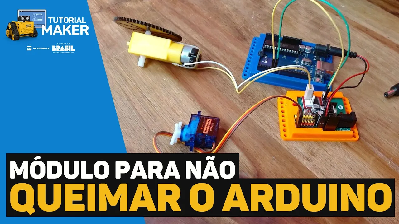
This video demonstrates how to safely power Arduino-based motor control systems by using a dedicated power module with voltage regulation. The module includes a P4 power connector accepting 9-12V input, an LM7805 voltage regulator that converts this to stable 5V for the Arduino, and an H-bridge (MX1508) for controlling DC motors and servomotors. The key principle is separating motor power from control circuit power: the main power source feeds the motor module, which then derives regulated power for the Arduino, preventing motor noise and current spikes from damaging the microcontroller. This architecture allows a single power source to simultaneously power both the motor control circuit and the Arduino while maintaining electrical isolation between high-current motor circuits and sensitive control electronics.
Click to watch →
Arduino DC Motor Control with Analog Joysticks
17.6K
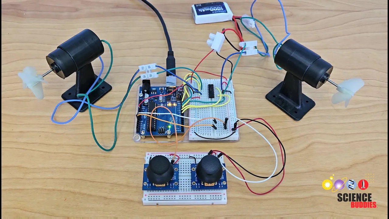
Motors require substantial current (often several hundred milliamps) that exceeds what the Arduino's 5V supply can safely provide. Therefore, an external battery (such as 9V) powers the motor section of the circuit through a separate power bus. The Arduino itself is powered through the VIN pin from the same external battery. Critical safety measure: never connect the 9V motor power bus directly to the 5V Arduino power bus, as this creates a dangerous short circuit that can damage components and the Arduino.
Click to watch →
Esp. en Arduino - Módulo VI Clase 1 (14/10)
401
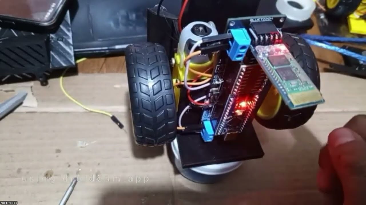
Robot circuits require proper power distribution. The motor driver's VIN pin receives main power (8.4V from two 18650 batteries). The Arduino's 5V pin receives power from the same source. The motor driver's VCC pin receives 5V for logic control. The Arduino's 5V pin connects to the motor driver's VCC to ensure both operate at the same logic voltage level. Different power supply voltages cannot be connected directly together. The 8.4V from batteries and the 5V from Arduino's 5V pin are different voltage levels and should never be connected directly. The 8.4V powers the motor driver's VIN pin and Arduino input. The 5V powers the Arduino's logic circuits and motor driver's VCC pin.
Click to watch →
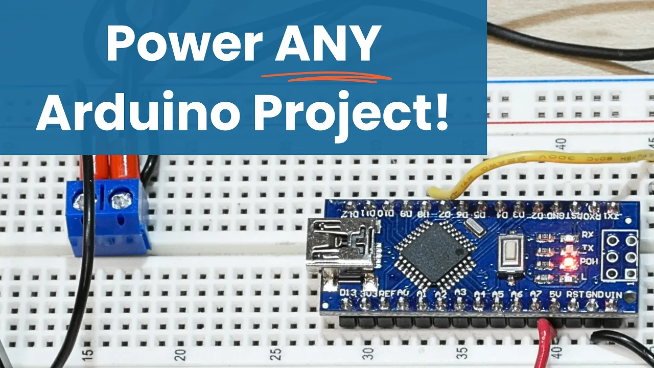
Power ANY Arduino Project - The Ultimate Guide
46.2K
When using multiple power supplies (e.g., 24V for solenoids and 5V for electronics), all grounds must be connected together to establish a common reference point. The Arduino is powered from its dedicated 5V supply while high-voltage components receive separate power. Critical safety rules apply: use only stable 5V supplies, never connect higher-voltage sources to the 5V pin, and disconnect the Arduino before programming. For portable projects, 9V alkaline batteries work well within the regulator's acceptance range. LiPo batteries offer higher capacity but require built-in protection circuits or newer Arduino models with integrated battery management to prevent fire hazards from improper charging or discharge.
Click to watch →
Prerequisite Knowledge
- Concept 01Basic Arduino programming fundamentals, including writing code, using the IDE, and managing digital/analog input and output pins.
- Concept 02The concept of Pulse Width Modulation (PWM) and how it is used to control motor speed and duty cycle.
- Concept 03The basic operation and circuitry of an H-bridge, which allows DC motors to run forwards and backwards.
- Concept 04Fundamental electronics safety rules, particularly the separation of logic-level power (Arduino 5V) from high-current motor power supplies.
Subsequent Learning
- Step 01Implementing closed-loop feedback systems using rotary encoders and PID controllers to achieve precise motor speed and position control.
- Step 02Utilizing the current sensing (IS) pins of the BTS7960 to monitor load, prevent motor stalls, and implement over-current protection in software.
- Step 03Designing and building heavy-duty robotic systems, such as differential-drive AGVs (Automated Guided Vehicles) or electric ride-ons.
- Step 04Transitioning to more advanced microcontrollers (like ESP32 or STM32) to implement wireless control via Bluetooth, Wi-Fi, or ROS (Robot Operating System).
Energy Surge
Build-Up
Climactic Loop
Uncertain Pause
Friendly Closing
Energy Surge
0:18Playing Section
- 1
Repeated vocal cues generate physical momentum.
- 2
Rhythmic chants establish a dynamic atmosphere.
- 3
Sound repetition drives early emotional intensity.
Limitations of BTS7960 and the Shift to Modern Integrated Drivers
While the BTS7960 is a popular, low-cost choice for high-current DIY projects, many electronics hobbyists and engineers advocate for modern alternatives due to several critical limitations. A major issue is the abundance of low-quality clone modules on the market, which often fail under heavy loads due to poor thermal design or counterfeit chips. Furthermore, the BTS7960's control architecture is highly complex, requiring up to six control pins per motor, which quickly consumes the limited I/O resources of an Arduino Uno. Critiques favor modern integrated H-bridge drivers (such as Texas Instruments' DRV series) or smart, communication-based controllers (like Roboclaw or Cytron drivers). These modern alternatives offer much smaller physical footprints, superior thermal efficiency, built-in current sensing, and robust hardware protection features (such as thermal shutdown and overcurrent protection). Additionally, they often use simpler control protocols (like PWM/Direction or I2C), reducing wiring complexity and leaving more processing headroom and I/O pins available on the microcontroller.
Deep Dive
Implementing closed-loop feedback systems using rotary encoders and PID controllers to achieve precise motor speed and position control.

The Ultimate Guide to using Motors in Robotics (including ROS, Raspberry Pi)
483.9K
Implementing closed loop control requires encoder integration and empirical calibration. Encoders use hall effect sensors that generate pulses as a magnetic disk rotates. By counting pulses and dividing by rotation count, we determine counts per revolution (e.g., 3,450 counts/rev). The controller uses PID algorithms to compare actual vs target speeds, adjusting PWM outputs accordingly. Commands like 'm' followed by target counts per loop enable closed loop operation. This demonstrates transforming theoretical feedback control concepts into working hardware implementations.
Click to watch →
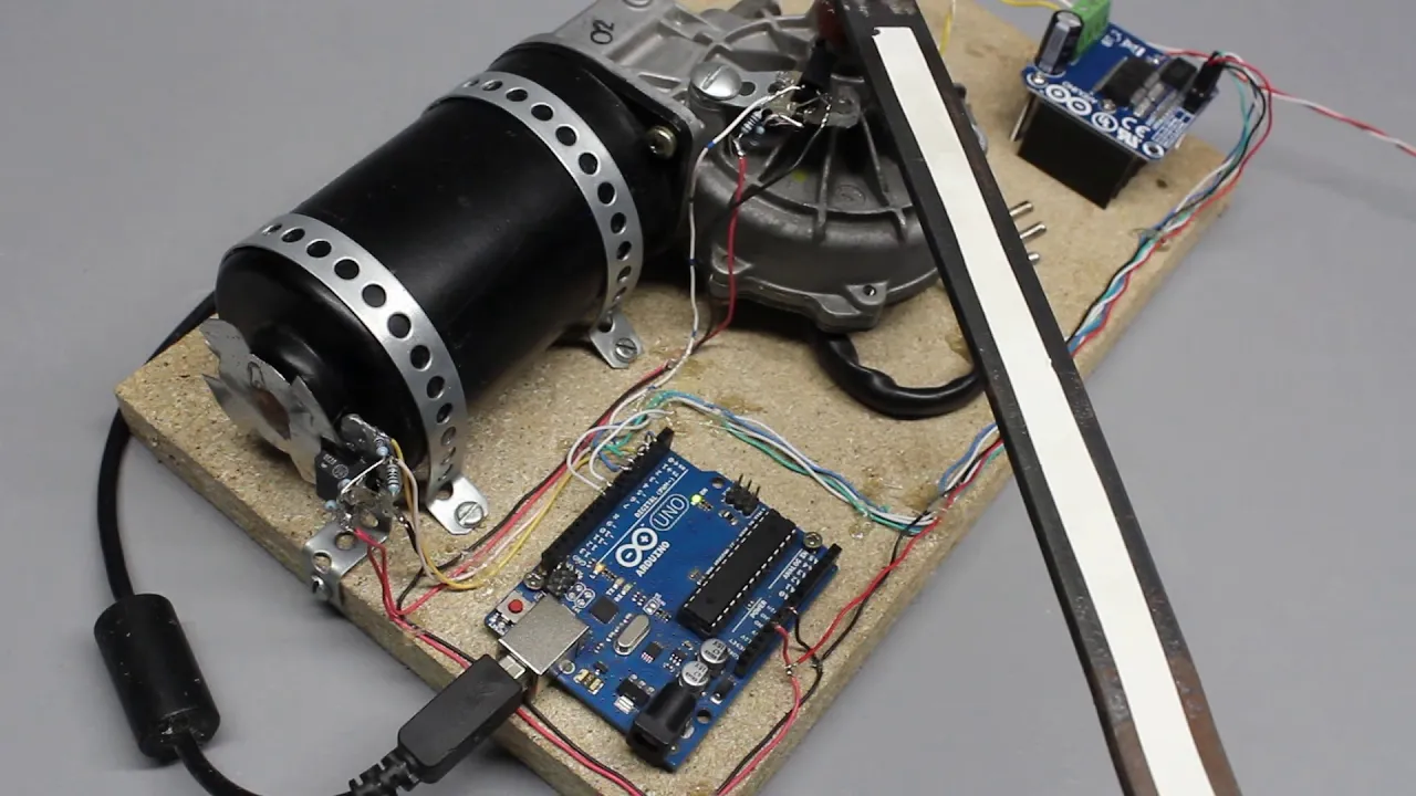
Rotary encoder or: How to build a digital servo using an Arduino and photo sensors
505.5K
Closed-loop control maintains accurate position by comparing setpoint (target) and actual position (sensor reading). The microcontroller tracks both values and calculates their difference. When the motor reaches the setpoint, inertia causes overshoot, creating oscillation around the target. To prevent this, the microcontroller reduces motor power (PWM) as soon as the setpoint is first reached, allowing slow correction of any overshoot. A proportional controller adjusts motor power proportionally to the difference between setpoint and actual position. When the difference is large, full power applies; as the difference decreases, the duty cycle proportionally decreases. A software parameter defines the relationship between difference and duty cycle, eliminating oscillations more effectively than simple on/off control.
Click to watch →
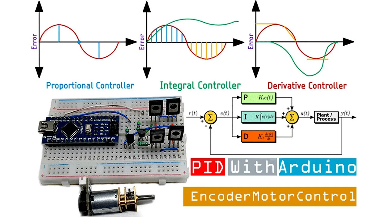
Arduino PID based Encoder Motor Controller | Arduino Projects | Arduino PID Controller
26K
A PID (Proportional-Integral-Derivative) controller improves motor positioning accuracy by continuously adjusting motor speed based on the error between the current position (measured by an encoder) and a target setpoint, unlike simple on/off control which causes overshoot due to motor inertia; the controller uses proportional gain to respond to current error, integral gain to eliminate steady-state error over time, and derivative gain to predict future error based on the rate of change, with the Arduino microcontroller implementing the algorithm through interrupt-driven encoder reading and PWM output to an H-bridge motor driver.
Click to watch →
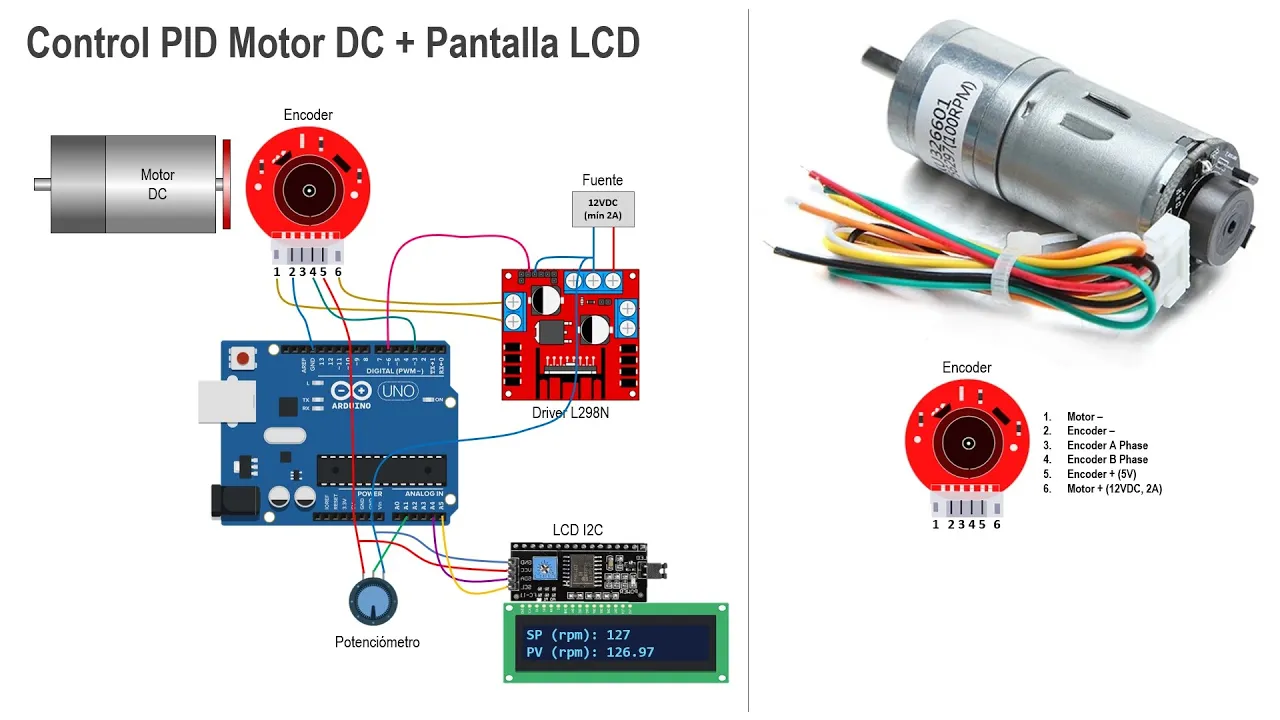
Control PID para Motor DC con encoder - Arduino
229.6K
This video demonstrates how to implement a PID (Proportional-Integral-Derivative) controller for speed control of a DC motor equipped with an encoder using Arduino. The process involves three main stages: first reading encoder pulses to measure motor speed by counting rising edges on a digital pin using interrupts; second calculating RPM from pulse counts by applying the formula RPM = (pulses_per_second × 60) / (encoder_resolution × gear_reduction_ratio); and third implementing the PID algorithm using the difference equation derived from the continuous-time PID transfer function, where the output is calculated as u(k) = Kp×error(k) + Ki×Ts/2×(error(k)+error(k-1)) + Kd×(error(k)-error(k-2))/Ts, with error(k) being the difference between setpoint and measured process variable. The final implementation includes an LCD display for real-time monitoring of setpoint and actual RPM values.
Click to watch →
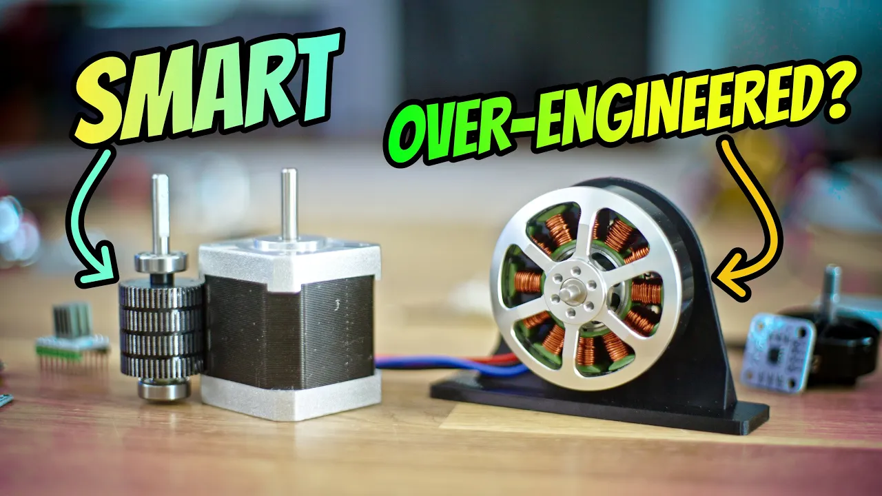
Steppers vs Servos in 3D Printers: An Engineering Analysis
280.8K
Positional feedback transforms any motor into a servo through encoders—magnetic or optical devices measuring rotational position. Magnetic encoders attach a magnet to the shaft and use chips to measure position, while optical encoders use graded transparent films or rotating sensors. Closed-loop systems detect external disturbances and compensate, unlike open-loop systems that lose steps silently. FOC requires precise rotor position knowledge to optimally control each coil, stopping current entirely when at target position. This contrasts with constant stepper energization, enabling dynamic current adjustment based on actual torque needs rather than fixed patterns.
Click to watch →
Deep Dive
Utilizing the current sensing (IS) pins of the BTS7960 to monitor load, prevent motor stalls, and implement over-current protection in software.

COMO USAR O DRIVER BTS 7960 (IBT_2 )+ ARDUINO EM PROJETOS DE AUTOMAÇÃO.
766
The IBT2 motor driver has current monitoring pins for optional current reading: Pins 5 and 6 are labeled R and S, which provide current output for the right side (forward direction). Pins 7 and 8 are labeled L and S, which provide current output for the left side (reverse direction). These pins can be connected to the Arduino for monitoring motor current and detecting overcurrent conditions.
Click to watch →
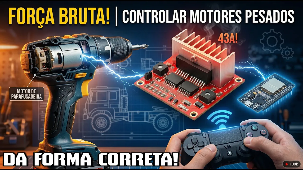
FORÇA BRUTA! Como Controlar Motores Pesados com Arduino, ESP32 e PS4 (Ponte H BTS7960)
150
The BTS 7960B incorporates multiple protection and monitoring features essential for safe motor control. The module supports PWM frequencies up to 25kHz, eliminating audible motor noise. The 74HC244 buffer chip provides critical functions: signal conditioning for clean PWM output, electrical isolation protecting the microcontroller from high motor currents, and logic level interpretation. Built-in protections include thermal shutdown (cuts power at dangerous temperatures), overvoltage protection (disables at >27V), and undervoltage protection. Current monitoring pins (R_S and L_S) allow real-time current measurement for diagnostic purposes. The enable pins provide emergency shutdown capability, crucial for safety-critical applications like children's ride-on vehicles.
Click to watch →
V99 Low Output Current Problem | SMPS not providing enough Current for Load | How to increase Ampere
171.1K
The current sensing circuit uses a small resistor (0.85Ω) in series with the MOSFET drain. As current flows, a voltage drop develops across this resistor according to Ohm's Law. This voltage is fed to the IC's current sense pin, which monitors output current. When the sensed voltage exceeds the IC's internal threshold (typically 0.5V), overload protection triggers, stopping the switching operation. The IC then restarts the switching process once the load is removed, creating a continuous cycle of shutdown and restart until the overload condition is resolved.
Click to watch →
Wie funktioniert ein Schaltnetzteil? - Grundlagen der Primärseite (Teil 1)
88K
Overcurrent protection uses the current-sense pin to detect excessive load current. The controller continuously monitors the voltage across the sense resistor. If this voltage exceeds approximately 1V (indicating more than the rated current), the controller immediately shuts down the MOSFET. This protection is triggered by connecting the 5V reference to the current-sense pin through a transistor (Q3). The transistor is normally off during normal operation but activates during fault conditions to force the controller into shutdown.
Click to watch →
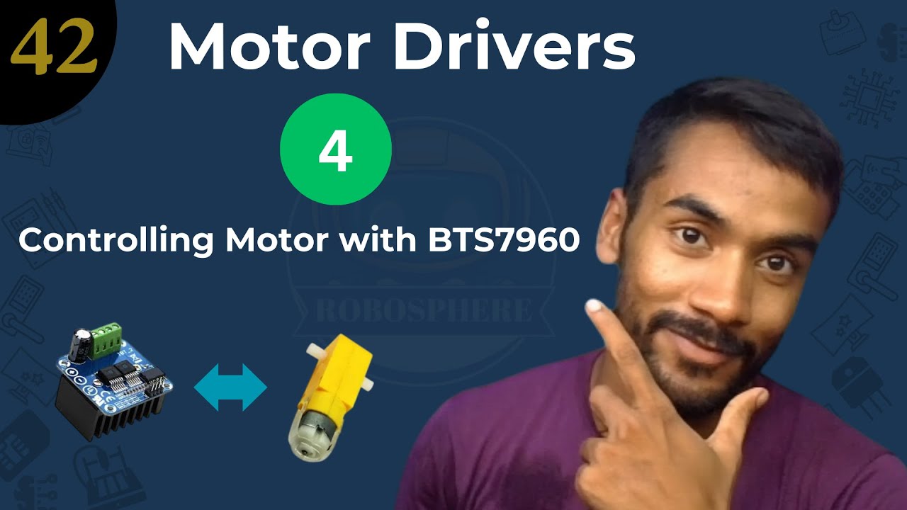
🎯 Lecture 42: Controlling DC Motor Using BTS7960 Motor Driver | Arduino Project
469
The BTS 7960 is a high-current H-bridge motor driver capable of driving motors up to 43 amps, compatible with Arduino and Raspberry Pi. It operates on 6-27V with 15A continuous and 43A peak current ratings. Unlike L293D/L298N, it uses dual PWM control with 25kHz frequency and includes built-in overvoltage, overtemperature, and short circuit protection. The module features separate control and output sections with clearly labeled pins for VCC, GND, PWM inputs, enable pins, and current sense outputs. The control logic follows: HIGH-LOW on PWM pins produces forward rotation, LOW-HIGH produces reverse, and LOW-LOW stops the motor. Both PWM pins HIGH creates short circuit risk. The LIS and RIS pins provide real-time current monitoring by mapping 0-43A motor current to 0-255 analog values (0.19V per amp at 5V reference).
Click to watch →
Deep Dive
Designing and building heavy-duty robotic systems, such as differential-drive AGVs (Automated Guided Vehicles) or electric ride-ons.
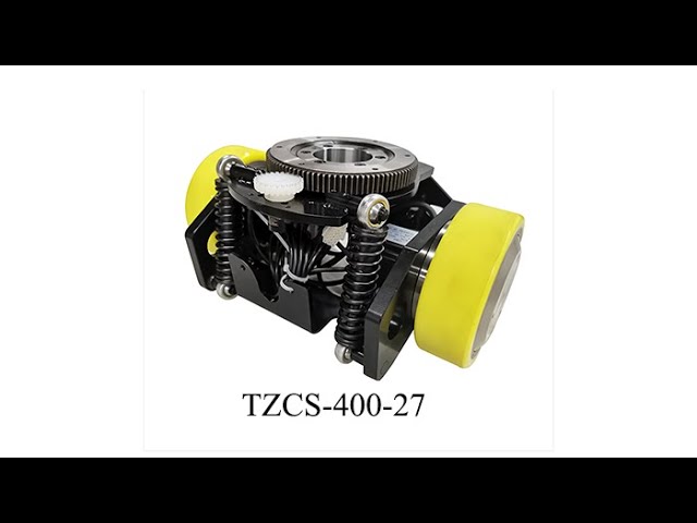
TZBOT Live commentary AGV Drive Wheel TZCS-400-27
3.5K
This video demonstrates a compact 400W AGV differential drive wheel system featuring two motors, two wheels, and a dual-channel driver that controls both motors with one controller; the system has an overall height of only 160mm, wheel diameter of 150mm, maximum load capacity of 600kg, and includes encoder feedback for precise angle detection, with spring suspension for better ground adaptation and low noise operation around 15 decibels.
Click to watch →
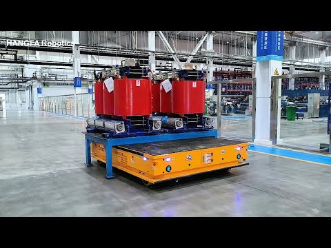
Heavy-duty AGV - 35tons / 25tons
213
Heavy-duty Automated Guided Vehicles (AGVs) are specialized mobile robots designed for transporting large, heavy industrial components such as transformer parts in energy facilities. These AGVs feature omnidirectional movement capabilities that enable flexible navigation through narrow industrial spaces, and they operate through either wireless remote control or automatic mode with preset paths, enhancing both operational safety and efficiency in standardized transportation processes.
Click to watch →

Hannover Messe 2019 LIVE - Schwerlast AGVs von Stäubli
3.5K
Heavy-duty Automated Guided Vehicles (AGVs) can safely transport loads up to 500 tons while integrating with automated stations and robots through automatic docking systems that connect safety signals, emergency stops, and light curtains. These systems feature elastic safety mechanisms in high-risk areas like tooling interfaces that immediately trigger emergency stops upon contact, preventing injuries while allowing quick resumption of operations.
Click to watch →
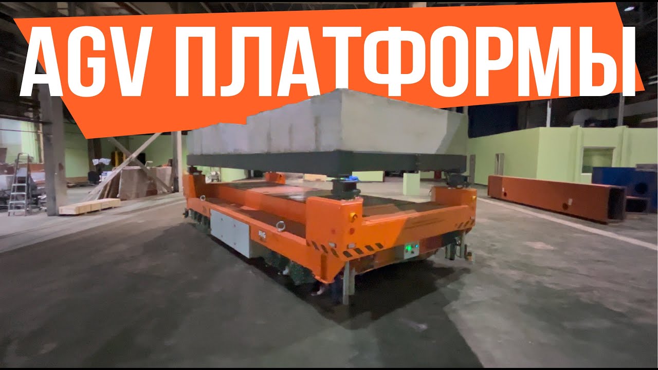
Система AGV платформ грузоподъемностью 40 т/ AGV platform system with a load capacity of 40 tons
302
Heavy-duty AGV (Automated Guided Vehicle) platforms with 20-ton capacity each can be synchronized to transport oversized loads exceeding 30 meters in length and 40 tons in total weight, utilizing omni-directional wheels for full mobility and mechanical lifting systems instead of hydraulics, with control systems combining manual operation and automated vision-based navigation.
Click to watch →

Industrial AGVs (autonomous guided vehicles) & AMRs (mobile robots) for assembly lines & fabrication
15.5K
Heavy-duty autonomous guided vehicles (AGVs) and autonomous mobile robots (AMRs) are specialized industrial automation solutions designed to transport extremely heavy loads (ranging from 10,000 lbs to 50,000 lbs or more) through manufacturing facilities, replacing traditional manual conveyance methods like carts, trolleys, and forklifts that were often inefficient and dangerous; these systems serve critical roles in industries such as electric vehicle production, aerospace manufacturing, alternative energy equipment assembly, and defense sector operations by enabling safe and efficient movement of heavy parts, work-in-progress objects, and finished products throughout complex factory environments.
Click to watch →
Deep Dive
Transitioning to more advanced microcontrollers (like ESP32 or STM32) to implement wireless control via Bluetooth, Wi-Fi, or ROS (Robot Operating System).

ESP32 vs STM32 vs NRF52 vs RP2040 - Which is Best for Your Product?
62.4K
When choosing between ESP32, STM32, NRF52, and RP2040 microcontrollers for your product, consider: (1) Wireless needs—ESP32 for Wi-Fi/Bluetooth, NRF52 for ultra-low power Bluetooth; (2) Battery life requirements—NRF52 or STM32L series for long battery life; (3) Budget constraints—RP2040 for lowest cost without wireless, ESP32 for best price-to-feature ratio; (4) Scalability and long-term options—STM32 offers the broadest range of part choices; (5) Development experience—ESP32 and RP2040 are easiest for beginners, while STM32 and NRF52 offer stronger professional ecosystems.
Click to watch →
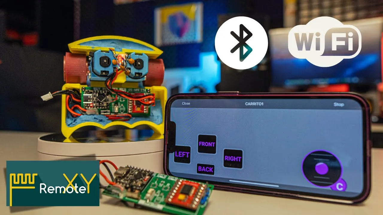
Controla tu robot con ESP32 C3 por Bluetooth y WiFi ¡sin complicarte! 🔧📱
21.9K
Modern microcontrollers like the ESP32 enable wireless communication through Wi-Fi or Bluetooth Low Energy (BLE), allowing connection to smartphones, tablets, and computers without complex programming. This tutorial demonstrates connecting an ESP32 C3 Super Mini to a robot using Remote XY application, enabling control via intuitive graphical interfaces. The approach eliminates the need for traditional remote controls or custom app development, making robotics projects accessible to beginners.
Click to watch →

How to Make Bluetooth and WiFi Controlled Car using ESP32 | ESP32 RC Wifi Car
8.5K
This comprehensive tutorial demonstrates building a mini soccerbot using the ESP32 microcontroller that supports both Bluetooth and Wi-Fi control. The ESP32's integrated wireless capabilities eliminate the need for external modules like nRF24L01. Key components include three 3.7V lithium batteries providing 12V power, a buck converter set to 5V for the ESP32, and a motor driver with PWM pins (14 and 32) for speed control plus four direction pins. The project covers hardware assembly, Bluetooth command parsing (F/B/L/R/S for movement, 0-9 for speed), and implementing movement functions including diagonal maneuvers. The complete system demonstrates how ESP32 serves as both microcontroller and wireless communication hub for mobile robot applications.
Click to watch →

10 ESP32 Pro Features: Take your Projects to the Next Level!
181.4K
The ESP32 supports both Wi-Fi and Bluetooth (including classic Bluetooth and Bluetooth Low Energy) simultaneously through a feature called coexistence. This allows the ESP32 to send data to the cloud via Wi-Fi while simultaneously communicating with nearby devices over BLE. This combination is ideal for smart home hubs, health monitoring devices, or industrial sensors that need to collect data from multiple BLE devices and transmit it over Wi-Fi to servers or dashboards. A demonstration shows the ESP32 connected to Wi-Fi while simultaneously broadcasting a BLE device name that appears instantly in BLE scanner apps.
Click to watch →

Bluetooth Classic & BLE with ESP32
74.9K
This tutorial covers Bluetooth communication protocols and their implementation on the ESP32 microcontroller, explaining how to use both Bluetooth Classic (for high-bandwidth streaming) and Bluetooth Low Energy (BLE, for low-power IoT applications) with the ESP32's built-in Bluetooth capabilities, including device discovery, serial communication, and GATT-based service/characteristic interactions.
Click to watch →
Energy Surge
Build-Up
Climactic Loop
Uncertain Pause
Friendly Closing
Energy Surge
0:18- 1
Repeated vocal cues generate physical momentum.
- 2
Rhythmic chants establish a dynamic atmosphere.
- 3
Sound repetition drives early emotional intensity.
Limitations of BTS7960 and the Shift to Modern Integrated Drivers
While the BTS7960 is a popular, low-cost choice for high-current DIY projects, many electronics hobbyists and engineers advocate for modern alternatives due to several critical limitations. A major issue is the abundance of low-quality clone modules on the market, which often fail under heavy loads due to poor thermal design or counterfeit chips. Furthermore, the BTS7960's control architecture is highly complex, requiring up to six control pins per motor, which quickly consumes the limited I/O resources of an Arduino Uno. Critiques favor modern integrated H-bridge drivers (such as Texas Instruments' DRV series) or smart, communication-based controllers (like Roboclaw or Cytron drivers). These modern alternatives offer much smaller physical footprints, superior thermal efficiency, built-in current sensing, and robust hardware protection features (such as thermal shutdown and overcurrent protection). Additionally, they often use simpler control protocols (like PWM/Direction or I2C), reducing wiring complexity and leaving more processing headroom and I/O pins available on the microcontroller.
Basic Arduino programming fundamentals, including writing code, using the IDE, and managing digital/analog input and output pins.
The concept of Pulse Width Modulation (PWM) and how it is used to control motor speed and duty cycle.
The basic operation and circuitry of an H-bridge, which allows DC motors to run forwards and backwards.
Fundamental electronics safety rules, particularly the separation of logic-level power (Arduino 5V) from high-current motor power supplies.
Implementing closed-loop feedback systems using rotary encoders and PID controllers to achieve precise motor speed and position control.
Utilizing the current sensing (IS) pins of the BTS7960 to monitor load, prevent motor stalls, and implement over-current protection in software.
Designing and building heavy-duty robotic systems, such as differential-drive AGVs (Automated Guided Vehicles) or electric ride-ons.
Transitioning to more advanced microcontrollers (like ESP32 or STM32) to implement wireless control via Bluetooth, Wi-Fi, or ROS (Robot Operating System).
20.7K views218likes4:52@_crazytechzOriginal Release: 2022-08-15
[Music] cash.
Trash me.
Heat. Heat.
Heat. Heat.
[Music] Heat. Heat.
[Music] Heat. Heat.
Heat. Heat.
[Music] [Music] Heat. Heat.
[Music] Heat. Heat.
[Music] Heat. Heat.
[Music] again.
I don't know.
[Applause] Heat. Heat.
[Music] Hey, [Music] hey, hey.
Heat.
[Music]
Up Next

13:38
Python QR & Barcode Reader: A Step-by-Step Tutorial
@Pythonenthusiast
87.7K views•2020-08-30

12:54
Triumph of Orthodoxy Icon: Byzantine Art & History Explained
@BenCallan
2.1K views•2024-08-06

9:49
FastAPI vs Flask vs Django: Choosing the Right Python Web Framework
@TechWithTim
302.5K views•2024-05-26

1:42
Game of Thrones Opening Credits: A Cinematic Analysis
@gameofthrones
46.3M views•2011-04-18
Related Study Plans & Knowledge Roadmaps
Structured learning paths in General & Interdisciplinary Studies
general-studies
Elevator Engineering: History, Physics & Cities
01From Hoists to Safety Brakes: The Dawn of Vertical Lift
02Hydraulic vs. Traction: The Engineering Physics of Elevators
03Modern Speed, Safety, and Algorithms
+ 2 more learning modules
12h5 modules
Explore Roadmap
general-studies
Rubber: Material Science, History & Geopolitics
01Origins of Natural Rubber & Mesoamerican History
02The Chemistry of Natural Rubber & Vulcanization
03The Geopolitics of the Rubber Boom & Colonization
+ 2 more learning modules
12h5 modules
Explore Roadmap
general-studies
Containerization: Evolution, Logistics & Trade
01Ancient Trade & Bulk Cargo: Amphorae to Barrels
02The Industrial Revolution & Cardboard Packaging
03The Containerization Revolution: Malcom McLean
+ 2 more learning modules
12h5 modules
Explore Roadmap
general-studies
Textile Tech: Evolution, Labor & Global Impact
01Pre-Industrial Textiles: Handloom & Cottage Industry
02Mechanization: The Spinning Jenny to the Power Loom
03The Factory System & Global Labor Transformation
+ 2 more learning modules
10h5 modules
Explore Roadmap