


















This tutorial demonstrates how to design a 3D-printed mecanum wheel chassis in Autodesk Inventor, covering key concepts including center-point modeling for easier assembly, offset tools for creating consistent wall thickness (10mm recommended for heat set inserts), extrusion techniques, and proper clearance design for motor and wheel mounting. The chassis must fit within a 10-inch cube for competition rules, with mecanum wheels requiring specific slant orientations (left-slanted and right-slanted) to point toward the center for omnidirectional movement. The design process involves creating a base frame, adding motor mounts with heat set inserts for secure screw attachment, integrating the PCB with proper clearance, and adding IR sensors at 4-6cm height for competition compliance.
Mecanum Chassis CAD Design Tutorial | Robotics Beginner Guide
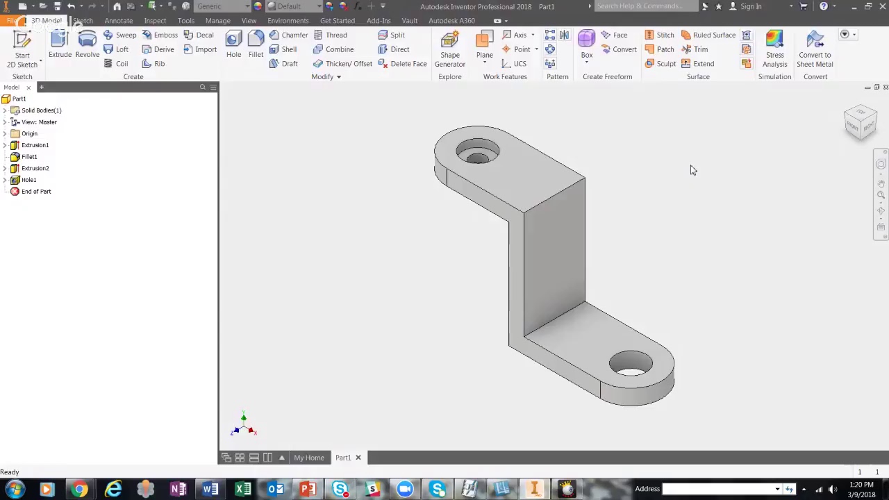
Added:All right, guys. So, now that we've gone over a bit of how to just, you know, make some stuff in Inventor, general like layout of what's happening here, right? We'll start making actual, you know, design parts. So, I'm just going to, you know, close out of these real quick. I don't need to save this. This is just a little test thing. So, the first part that we're going to start with is the chassis. So, the chassis of the robot, as I mentioned in our mech workshop, is the base of our robot.
That's where our wheels go. That's where, you know, all everything goes really in terms of the structure.
Everything is mounted off of our chassis and all of our electronics are housed in our chassis. So, this is usually a good place to start when designing a robot.
Right. So, we're just going to make a new file right here. Standard part.
Right. So, the way we're going to design our chassis is we're going to have it be 3D printed. Right. And essentially, um, I'll just kind of make a make a vague drawing to sort of give you the idea of how it kind of would look. Um, essentially, we're going to have like a rectangle, right? And then we're going to have this, right? So, it'll kind of be something like like this, right? I'll putting in random dimensions just to give you a visual. So, it'll be sort of like a box and then our wheels will kind of go in the sides and then we'll put like a little floor in there with holes cutouts for the wheels. I don't know. I'll just quickly give, you know, something here, right? Just so there'll be like a little bit of a floor, right? Put four squares for a cutout, you know, for where the wheels will go.
Right. Again, this is very rudimentary modeling just to give you guys visuals, you know.
So, yeah, that that is really thick.
What What did I mess up?
I don't know. Anyways, yeah. So, the wheels will kind of go through there.
Your motors will be over here, right on the sides. And that'll sort of be a decent frame for your robot to start off with. Is this the optimal frame for your robot to start off with? Not necessarily. But I'm just sort of here to give you a general idea of how you can go about designing your robot. And this is just a demonstration of a medium level robot that can do okay at the competition. And after this, it's sort of up to you to make the optimal design.
So yeah, anyways, let's just kind of start from fresh. I this is just sort of uh a quick walk through of like what we're trying to do. Um let's just delete all that. And uh I actually would like to start on Yeah, let's start on the Yeah, we can start on the base. So, first thing we're going to do, right, we want to start on the bottom, and that'll be down here. So, we can just make a rectangle.
And so, note for something when you're cadding is um you want to do a lot of your modeling about the center point because that just sort of makes your life a lot easier, right? In terms of, you know, how your planes line up, right? then everything's aligned to these, you know, coordinate axes and constraining stuff in your assemblies become a little bit easier and your parts just a little bit cleaner, right?
And it's easier to put together. So that's why I recommend um so usually when you, you know, open a part, make a new part, right? It'll give you this two corner rectangle. I suggest always switching to this twopoint center rectangle because this rectangle you define it by point to point and you do whatever and that's okay but it's a lot more convenient to usually define your rectangles from the center right like this and then after this we'll put in some dimensions um so a robot has a first 10 inch by 10 in size restriction that that that's just a rule for internal comp Right. It has to fit in a 10-in cube. And we'll like put your robot in in in a literal cube to test that out at the inspection table.
Right. So now, of course, we don't want it to be this big. We're actually going to change these dimensions up and make them a lot smaller so that you fit comfortably in there. Uh let's just make, you know, like like seven in.
Yeah, seven inches seems, you know, fine. seven inches by seven inches.
Maybe seven and a half might give us a bit of extra, you know, playing room.
That that's in millimeters. That's the default units. Um, and then I'll pick like a round number in millimeters to kind of go off of.
I just wrote it out in inches because it's just being American, my my brain auto thinks in millimeters a bit. I intuitively know what seven and a half inches looks like over 192 millimeters, which is why I wrote that in first. Um, and if you define, you can define the units in here and it'll, you know, know what you're talking about, which is nice when you're making a dimension.
Um, and then something else nice is, um, so I know that we want our robot to be a square. At least I want this demonstration robot to be a square. You have free will. Do what you want. Um, if you go in here and you click on a different dimension, you can set this dimension to always equal that dimension. So, it's a sort of like an an equationbased, you know, dimension that's based on this one. This is like a variable. So, if I change this, if I make this 200, this will also expand. So, it's just a convenience thing. Let's bring this back to like 192 or whatever I put it. And this dimension isn't too specific right now. And we'll maybe change it as time goes on. And then we'll create that box structure we did earlier, right?
And so we could make another rectangle or we could just offset this rectangle here, this square here, and define the wall thickness, which is more of it just kind of goes in line with what we were talking about yesterday on the other video, right? Which was, you know, does having your CAT software know what your design intent is. So there's this tool here, offset tool, keyboard shortcuts O.
You can click on here and it just sort of like offsets this part. And so think about how we're making this, right? It's like we want walls, right? This is what we want it to be. And we want a wall of thickness uh 10 millimeters, which um I'll kind of explain why in a bit, but essentially um for using the heat set inserts, um it's just that um we want the walls, you know, thick enough so that you know it sort of holds it in properly and doesn't make a mess, which is why I I make them, you know, 10 mm thick. And I'll show you that as when we design that section. So yeah, I want 10 mm thick walls.
And so that's why I designed it using that offset tool. Now what we now something you might notice is that this is also 172 mm. If I if you hit M, that pulls up the measurement tool and you can click on lines and see, you know, how big it is. So another way you could make this is you know using your rectangle tool 172x 172 but note that if I change this to like 300 this won't follow with and knowing how we want to design a robot know we always want the wall to be we we're defining the wall thickness more so than the actual inside space of our robot. So that's why we want to use the offset tool instead to, you know, create this feature.
So yeah, here's that. Do that. Finish that sketch. And we're going to use that extrude tool. E is the keyboard shortcut. And we're just going to extrude this all the way up. Um we'll give a tentative number of like I don't know 24 for now. Um we'll see how that works um later on. But anyways, so now we have that that square shape. Now let's sort of move on and let's try putting in the motors. So how are we going to do that? We actually have a CAD model for the motors inside of our inside the folder that you guys, you know, downloaded already and put into your inventor, you know, folder, right?
you know, um, if I go into my documents, Inventor, right?
Comp robot 2025, right? The kit and it's all in here. Your motors are in electronics right over here. You got an a step file, which is a very generalized CAD format.
Um I gave it as that because and not an inventor file because in case anyone wants to use a different CAD software.
So um the way you do that is you go in file open and we'll go into kit and electronics and open up motor.
All right. So we'll just kind of hit okay. Those are just some settings for imports. And I'm just going to do my whole like changing the viewer settings, right? So we get those like clean lines.
And so now we see this is what our motor looks like. And what we're going to want to do is we're going to want to mount this onto this face here. And from there, we're going to put the wheels. So, in order to do that, we have these two screw holes in here that, you know, we put the screws through and we can screw it into this, you know, wall here. So, that means we need holes here for the screws to go into. And more specifically, we're going to use these things called heat set inserts, which are, you know, brass inserts. I can look some up for you guys to, you know, see heat set inserts.
Right. They're essentially these things.
They go into a part and into a 3D printed part. You can sort of like melt them into there and you can screw into them. And that's how you can screw threads into, you know, 3D printed parts, you know, like metal threads, right? And it'll be more stable than say printing a 3D printed, you know, thread for your screw to go into, right? So what we'll do is start a sketch here right and we'll first actually we'll measure you know the distance between these two holes is 17 and 12 mm right so we'll you know make a you know I'll actually make a line here of 17 and a half and I'll make it a construction line because I'm using this as sort of like a geometry reference, right? And then I'll put two circles here, right, of um size uh 4.5.
So the screws holes themselves are 3 mm.
Yeah. But for the heat set inserts, um the inserts are a bit larger than the screw and the right diameter for those inserts, the the 3 mm screw inserts, they're called M3 screws or 4.5 mm. Um that's just something you just got to know or look up whenever you design these sorts of things. Yeah. So 4.5 mm, right? Um something you know is I made this line. Um this line was more of just a convenience thing but you could also define how these two are related to each other using these constraints. So the first thing notice that these two holes are you know literally aligned with each other. Um if this is you know the orientation they're vertically aligned.
So what we can do is use the vertical constraint to make them vertically aligned to each other. And then we can use a dimension. Um so here dimension you can click on that or know the keyboard shortcut which is D because you know you use that a lot right so which is D and you know it's what 17.5 as you mentioned before right so now these will you know go wherever that being said I do like doing it by the line because it gives us one extra thing we can do and that we can also let me just quickly 17.5 is we can define it. We can use the center point of this right to define where it's located which is uh pretty convenient right if we want this is so we we have like the center of this essentially as like a geometry point we can you know use to create sketches with right so let me just make this a construction line I'm kind of on a trackpad this is kind of awkward but anyways um yeah so like I mentioned actually we're gonna if you have is centered. So now this point here, well I could project it or it will we can project the center point of this line right here and center it with here because I know this this line is you know the whole length of this and the center is of course at the center right. So I can use the horizontal constraint to make so these two are lined up. the center point of this line and the center point of this line so that this whole, you know, setup is, you know, lined up completely, right? So, I'm going to make this construction probably doesn't make a difference, but it's cleaner anyway. So, now this is, you know, kind of free spinning only this way, free moving, and we'll define that later. It's not an important feature right now. Now, we'll go into here. And something to note is that um we have this motor shaft, right?
And it's on both sides. So we need to account for that and you know put a hole on on this side here so that this can you know go through and you know not phase through our frame right cuz do this right you know this hole is where you know it'll screw into the motor and then that shaft will probably be like you know over here. Well let me just drag this over here. Right.
Motor's over here. Shaft is going to be over here kind of sticking out, right?
So, yeah, what we'll do is we'll, you know, just measure out where that is.
What I like to do is I just create a sketch and I can project these lines and I can project these geometries here and I can sort of just straight up measure it by creating lines because the measure tool is sometimes a little bit limited and it's just easier to you know make a sketch and you know just measure everything out.
Um make sure that's vertical. Well, I'm I'm rotated sideways. Note that um Inventor has like the vertical and horizontal constraints are relative to the the global orientation and not where you're looking. So I'm hitting the horizontal constraint, but it's actually, you know, vertical from how we're looking because, you know, we're looking at it sideways. If you look at this view cube, that's the orientation you're at. Um anyways, so now we can measure this. This is 20.6 mm to the left. And well, relative to the center, it's in it's in the middle, right?
And you could also just measure this also with the measure tool. M, right?
Oh, for the record, the measure tool, the button is located in tools, but I ain't going to the tools menu just to hit one button. Just hit M, right? And you'll get your measure tool.
Anyways, let's control Z our way out of here. Or wait, I forgot the number. I think it was 20.6. six. Yep. Anyway, so let's control Z our way out of here, right?
And let's go back here. Uh, we're still in our sketch here. So, let's just make a circle. Oh, by the way, the keyboard shortcut for a circle is control shift C. Um, or you can just click the circle button. But as you get more fluid in cadding, you're going to probably gravitate to just using your keyboard shortcuts. Um, this shaft is like somewhere between like I think it's like 4 and a half millimeters in diameter. We want it to just have complete clearance. So, I don't know. We can make it like 10 millimeters. You can do anything as small as like 5 millimeters technically speaking, but you know, I don't care to take risks like that. I don't it's no real point.
So anyways, let's just horizontally align it to the center. Right? And then 20.6 here to here. Right now, as I keep cadding, I'm going to like give you guys less details of everything I'm doing because I'm assuming you're picking up on how this is working now. So I'm just going to kind of start doing stuff, right? So I'm just going to make a reference line here to the center. And I'm gonna make this construction all these ones because I just projected this line too to get the center point. Um, so now something to note is for a four-wheel, you know, chassis, I'm going to have one wheel here, one wheel here, but I'm going to want, you know, mirrored, right? I want it all symmetrical. So what we can do actually is select these three circles.
You can shift select them to select multiple. And then I can mirror that about a mirror line and it'll you hit apply it'll create a mirrored section right there. That's just a convenient thing. Then again tells inventor what you want. Essentially you want it to be mirrored, right? And say if you ever change it, it'll know. Anyways, I'm going to define how far out it is. Um, I don't know exactly how far out it has to be.
We'll see when we assemble it. And so I'll just kind of give it a random number for now. And we can essentially what I mean by that is we can take a measurement in our assembly and see how much we need to adjust that. So for now I'm just going to be like that's okay.
Finish our sketch and I'm going to extrude that.
So now what I'm going to do is I'm going to extrude this. So now there's two ways about going about this. One thing we do is we can actually there's different types of extrusion right. So first of course I mentioned last time right there's the you know the distance extrusion right and then there's the you know two-phase extrusion right and you can maybe even go to like you know this face specifically. So you can cut this out here or you can go to a different phase, right? And then there's also the through all which means it just kind of rips through the entire part. Now in this instance, actually this is the most efficient way to design it because as you can see, we want it mirrored on the other side and this kind of automatically mirrors it for us, right?
So I'm just going to hit okay and have it just cut through all of it.
Yep.
Um, something to note is again I made this this vertical height just kind of randomly. Um, it's kind of getting close to the edge of this. So, I'm going to make this actually a bit taller. Just go back into the sketch, right? Hit the drop down, double click the sketch to edit it, and um, I realize that's not the feature. I I don't need to affect the sketch. I just need to make this taller. So, I'm going to go in here, make it like 36. not 376 36, right? He gives a bit of space. And that's actually important because um when we use the heat set inserts, the way we place them in the hole is we use a soldering iron to heat it up and it sort of like melts its way inside. And so if there's very little clearance to the edge, it'll sort of like melt out a little bit and be really messy and it won't line up properly. So yeah, that that's why. Yeah. Oh, by the way, you can, you know, redo things you undo by control Y. Also works in Google Docs.
But yeah, anyways, so that's that. I'll actually save this quickly.
Put this in our chassis folder.
And we'll just call it the chassis base.
Is it sort of like the base of our chassis or you can call it a frame or whatever you feel like. I don't It's not that deep. And um it'll actually start an assembly file because then you'll kind of get a sense of how this is supposed to look now. So new assembly and we're going to place in our chassis frame base right here. And we're going to do what I mentioned last time which is rightclick place ground at or at origin. And so something to notice is that in our assembly file, the center of our assembly file is also well, okay, well, it's not the center of our CAD file, but that's because I didn't center this. Um, something to note is that, um, you can actually do that and it'll like center it. But again, this is more of a cleanliness detail than anything. Um, the whole centering thing, you don't you don't need to go insane over it, not going to lie. Um, yeah.
I'm not going to save that just yet.
Anyways, get our lines in. Um, yeah.
So, after that, let's just import um some motors in and let's see if those motors fit in here.
So, kit kit, right?
Um, electronics and motors right here.
And then I'll save it.
Uh yeah, I'll just um yeah, call this a chassis assembly, right?
These were assembling your chassis.
Something to note is it'll actually create inventor files of this motor, right? Because um what I gave you is a step file and after you save it, it'll create an inventor file for all that.
So, you know, give it, you know, a second to save, right? And now, let us place this motor in. Now, I'm going to place this side and not this side because there's this little nib on here, and I don't feel like designing that.
So, I'm just going to, you know, use this flat side for our convenience. So, I'm going to mate this to this face. And then I'm going to line up the holes right here, here to here, and then this hole to this hole, right? Using those, you know, axis mates, right? And it'll go right there. So, something to note is that um this is actually clipping out the end. So, clearly this, you know, motor, these motor holes are too far outwards and I need to bring them in.
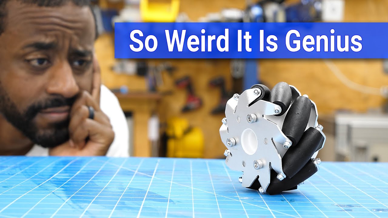
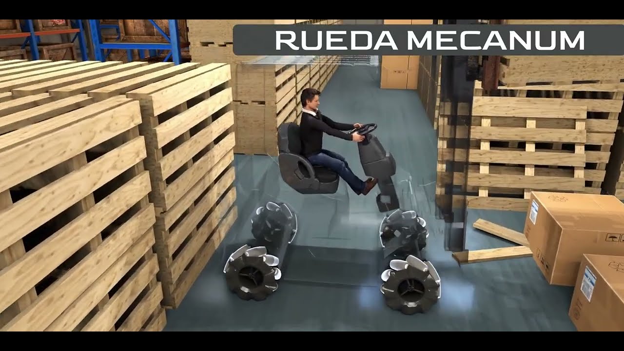
But, let's also add in a wheel. So we can even see that on here. So let's just import go in here. Wheels. Um so we're going to be using mechanum wheels. And um something about mechanum wheels is that um let me just pull this in.
They're omnidirectional and they have a specific slant. So this is a now left slanting wheel which means uh let me just uh let me just actually constrain this on because you have to look at it from a top down orientation in order to see what I'm talking about exactly. Right?
So just constrain that there real quick.
If I look at it like this, it um the top is slanted, right? And the higher side's on the left side and it goes down to the right side. So this is a left slanted mechanum wheel, right? Because it goes left to right like that.
Um and then if we import the other wheel, you can get a right slanted mechanum wheel.
And I'm just gonna delete you or Yeah.
And I'll show you this one right here. And look at it from a top down view.
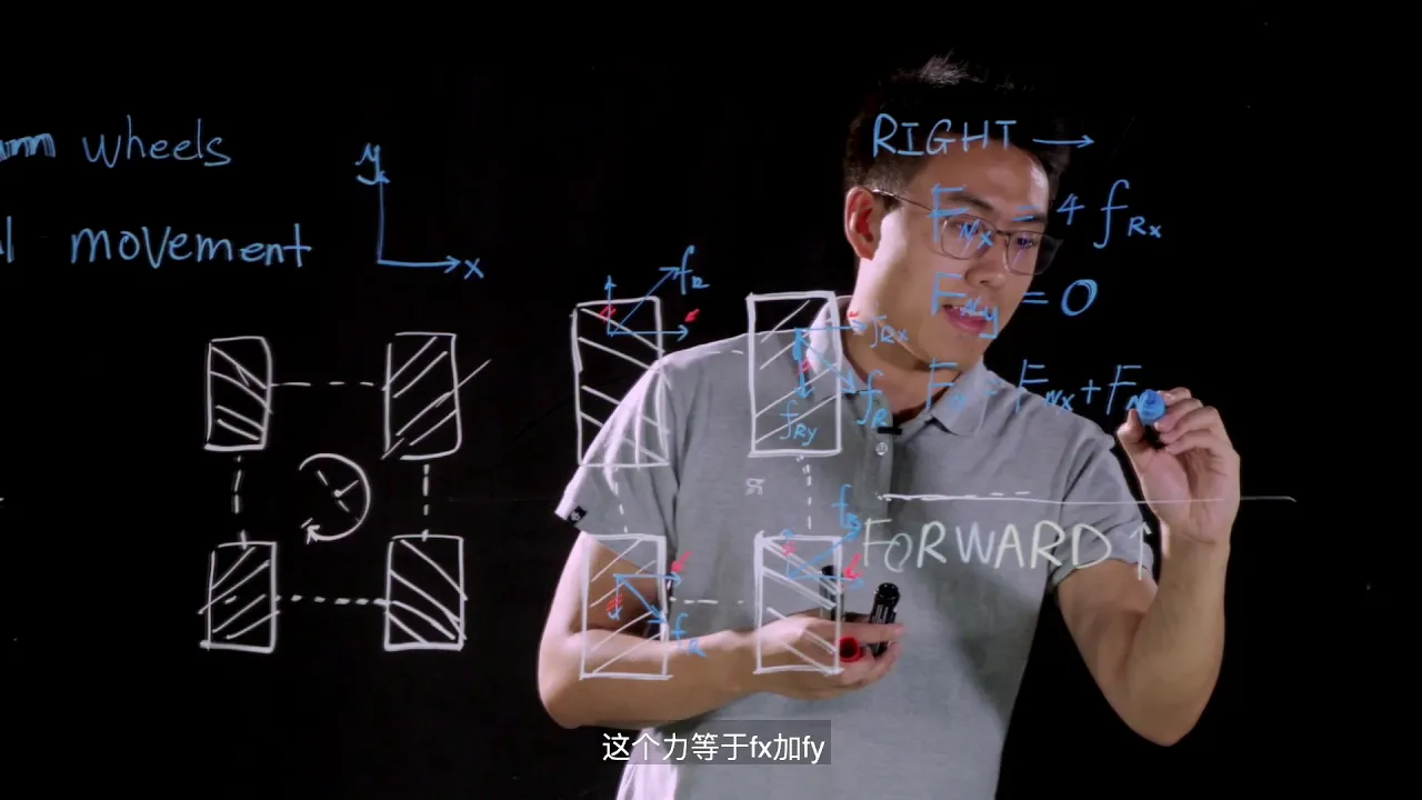
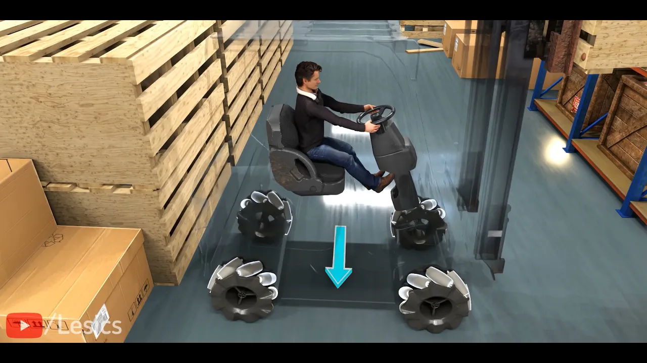
Let me rotate this. Yeah. Now it starts on the right side and goes down this way. So just a little note about you know designing with mechanum wheels. So from the mech workshop you might remember that these wheels let you go you know in all directions and that's what these rollers are for. And in order to have that functionality you need to have these rollers pointing a certain way. We're essentially you have four wheels and these rollers should point to the center from a top down view. Note it will look the look different from the bottom. As you can see, this is pointing away from the center from the bottom and towards the center from the top. It's an X from the top and an O from the bottom.
And you'll see that after we finish putting in all the wheels, right? But anyways, let me just So, what the first thing I did, I'll just restart constraining this so you can actually see what I'm doing. Right? Paste that again. is I'm going to So, how it's going to work is this face over here, right? The ends of this. So, we're going to put it on the shaft, right? And so, this bit here will end up pushing against the far inside of this piece on here on the wheel, right? And so, we'll constrain those two together to create this. And then I want this shaft to be concentric. But this one really I can pick any concentric feature there like that. Any circle that's you know at the center of the wheel essentially. So now this wheel spins and stuff. We can see that the wheel is clearly outside the edge of the chassis. So what we're going to have to do is bring this motor in. So let's open you up again. our chassis base, you know, also navigate to it using this bottom bar. And let's just um edit this sketch in here. Um let's look, the sketch is over here. So, let's just rotate our camera to go over here and bring it in a little bit. Uh I don't know, something like that.
Uh, maybe you can even go a bit more.
Who knows?
Probably get away with like that. That's probably fine.
Um, save it. And then over here, now the way to update this is you hit this little lightning button and it'll update, you know, all the parts.
And so now here, now that we've done that, we can see that, you know, the wheels completely inside with a little bit of space to go. This is perfect really because you don't want this like a millimeter away just in case like something bends because the one thing CAD doesn't really simulate is bending.
Um because these are all like solid, perfectly rigid parts in a CAD file, right? Um you can simulate bending but that's a lot of effort time and um kind of add a scope for this video so I won't show that. Um so now here we'll just now put in this motor in put in this wheel and see how that looks. I already see a potential problem that we might run into but we'll save that for when it happens.
Uhhuh. Let's just put these. I'll line this up. Hole to hole.
Right. Hold to hole. Yeah. As you can see now, issue is that these two are clipping into each other. Right. So, what we'll have to do is just make this whole thing a bit wider because I can't push this out because this is here and you know I can't really, you know, do anything else right in order to separate these two. So, what we're going to do is go here and make our whole chassis just a little bit wider to, you know, accommodate that, right? So, this is 192. We'll make it like 204.
Give it a little bit of space. Um, now, generally, if you're like working professionally as a CAD, something you might know is um this is very um guess and check design. So, it's not exactly the best of practice, but for something, you know, simple like this where the specific locations of stuff aren't the biggest deal ever, it's kind of okay.
It's not that important. Um, anyways, so I made that wider. Now, let's push this out a little bit right here.
Um, I think I probably need a bit more space. Maybe make it like 42.
Save that. See how this looks.
Yeah. Um, now actually I did kind of leave some space here. What I could have done is literally measured out the exact distances that they were hitting and I could have pushed it out by that much.
But again, this is very simplistic design. So it's not that deep at the end of the day. I'm not going to sweat over it. It's kind of faster to just quickly see it and make some adjustments.
And you know, again, depending on the precision of your, you know, design level, your of what you're making, you know, you can add more or less details.
So, in this instance, um, in order for this to point towards the center, right, this one's pointing inwards. This one, if I put this here, right, it'll never point inwards. It'll always point like this. So, what we'll need is a left sling wheel so that it, you know, points in [Music] all slant right here.
And we'll just assemble that wheel on the same we did same way we did the first one. So that inner face to this face and then we'll just take any you know axis feature that's like you know centered and same with the shaft right there.
Perfect.
So now something to note here is that um this thing is clipping into the wall as you can see this little plastic cover on the motor. So, we just need to give some space for that so that it can breathe.
And also though the wires that they come off of these little like you know copper, you know, bits over here. That's where the wires for the motors come out.
So, what we'll do is we'll open this and just sort of create a little cutout in there just so that there there's space for that. So, I'm going to go in here and uh I'm just going to make a little rectangle in here.
Something like that. Give it some some quick dimensions.
Uhhuh.
And something we can do actually is measure how tall this is.
This is this would be the tallest point on there. Uh so that's 12 millimeters.
And again, better to just give some extra room than less room.
So I'll make it 24 or like 20. Not that important.
And then just set it in by I don't know a few millimeters. It's not too important. You can even cut it all the way through if you want.
you know, but I'll I'll keep it enclosed because, you know, I guess it protects the motors a bit more if there's no like access from the outside to the motors, right? It's a little bit safer.
So, I'll just cut it in by 6 mm, right?
That should be fine.
Um, I did on the other side, didn't I?
Yeah. Okay. Um, anyways, we do need it on both sides.
The one thing I will do is I will round these corners with the filler tool.
Keyboard shortcut F. And this is more of just an aesthetics thing. Um to be honest, makes it look nicer. Um I try to avoid having sharp corners on my designs too much, you know, especially with working with metal. There's a lot of reasons why you don't want to have sharp corners, both on a safety perspective and also a manufacturing perspective.
It's hard to make sharp corners, but um for 3D printing, it doesn't matter. It just, you know, looks a lot nicer. Do that, you know. And now what I'm going to do is I'm going to mirror it to the other side. So, this is where that whole like little spiel I had about like having your plane centered actually matters. So, I'm going to hit the mirror tool. And now, if I just, you know, click the origin plane of uh this this origin plane, it'll just, you know, mirror all the way over like that.
Shoot. I failed. Okay, I probably Let me just I probably just did something wrong. Anyways, let me just mirror.
Right.
And I'll click on the plane.
Right. This one right here. Perfect.
And for some reason, now let me try with the fillet. I did it without the fillet.
Now, let me try this with the fillet.
Sometimes mirrors are a bit finicky when you have, you know, special features like the fillet included.
Right now, let's try mirroring over here as one whole unit. Okay, it works. I probably just clicked something weird the first time because I was talking, but yeah. Anyways, so now that's mirrored over, right? So, we don't have to, you know, redesign it on the other side. It just kind of is there. Save that quickly.
Look over here.
And as you can see, there's a cutout for that. Let's see if it's long enough.
Uh, no, it's not.
You know what? Let's just quickly hide this and let's measure how long that is.
Um, the keyboard shortcut to hide a part in assembly is altv, right? Or if you right click, you see uh visibility right there. Hides it. Um yeah. Oh, you're probably wondering what that popup was right here. This essentially means that if I because this is an assembly right here. If I hide something in it inside the motor assembly of here, right, it won't update if I hit okay is essentially what it's saying. um which um I don't really care about for the motor, but you know, I'll say no for now. I don't need to hide it.
Anyways, let's u measure this out real quick. Um this face to this face is 28.
Actually, no. Actually, what we want to really measure is this face to this face all the way over here, right? And that is 56.9.
Brilliant. Okay. Now let's uh control Z to unhide it. Or what we could do is find it on the menu and hit altv again to re you know visualize it. And let's go back here to the chassis base.
Edit this. And so 56.9.
We'll make it a bit bigger than that.
64. Give it some space, some breathing room. Save that. Um, but it is getting a hair close to this hole. So, let's just quickly edit that a little bit. Make it like 62.
You know, a little bit of breathing room is nice, you know, cuz again, that whole melting thing I mentioned, just, you know, be on the safe side of things. Anyways, chassis assembly. Let us update that even though there's nothing really to move. Um, and you can see that that has, you know, full clearance there and there's nothing, you know, hitting, right? Perfect. And also with that extra vertical clearance that we put in, right? Um, it because remember that this thing is 12 mm tall, right? But we made 24. And that makes so that there's extra space for the wires to go through comfortably essentially. And in fact, we could even make it a bit taller. But, you know, it's I don't know. Yeah, we'll make it a little bit taller. Give the wires a bit of extra room.
Perfect.
You know.
Yep. And now we'll bring these over to the other side of these motors.
So constrain this flat face. Bring you right over here.
Right. Um well, when I move that there to kind of block those holes, I'll just constrain these first. This one right here. Here to here. Like that. And then just copy paste you again. Actually, you can like paste multiple times. I didn't need to recopy it, but I don't know.
Yeah.
Uh, right here to here. Right there.
Move you out.
And shrink you to there. And I can't see it, but you know, I can just kind of move this until I can see it. And then do that to that. And we're we're back.
And I'm a clown. I put this the other way around.
Let's just do that again and train you to here right over here. Move you out of the way and bring here. You know, that's just sort of a thing that happens in your canning.
It's very spatial. So, you know, you just have to be aware of how you're, you know, lining up those holes.
Anyways, let's put in the wheels. So, looking like this. this wheel. Well, this will get flipped when I, you know, because the the yellow bits on here, and this this bit is what interfaces with the motor shaft. So, realistically, this would go here because it'll point this way when I like mirror it over when I rotate it the other way.
Let me just go back here.
And again, like we did earlier, the inside of that bit all the way into here.
Right.
And this to here.
Yeah, we I was right. Right. No, I lied to you guys. I'm stupid. you know, that did not get mirrored. Um, I'm a clown, a buffoon. Um, yeah, these are kind of like I don't I don't know, bro. It's it's just geometry.
My visualization skills were lacking.
Anyways, this goes here, right? Because you know that that clearly was not pointing towards the center earlier.
Anyways, let's move that over. You know, this is a lesson. Anyone makes mistakes, even someone as skilled and excellent at cadding as me, you know. Anyways, there we go. That That is right. Right. There we go. Pointing in towards the middle.
Perfect. And now let let's get you right here.
Let's see if we can see the inside of there again. Again, make another constraint.
hitting C that can that constraint keyboard shortcut and then you know doing this not that again the axis because again it's just sort of a convenience thing also because if I hit this and I have to find this I have to find the exact you know center or I guess I could do that but you know it's a cleanliness thing it's a habit thing um do what you like I guess in your own CAD models But anyways, yeah.
So now our wheels are in place and this is this will work relatively well. Um, but something to note about designing magnum wheels is that it is a good idea to have them as in much of a square of an orientation as possible, right? So that like they they work evenly. As you might notice, it's kind of like a rectangle right now because we just kind of made up the dimensions, right?
So what we can do actually is we can open this first of all and we can essentially measure the the what we can do is we measure the center center distance and what we need to do that is find the the center is to find make a plane the center of this and use that to measure. Now, for these um wheels, um I don't think I kept the center plane in the center when designing it because they were like really weird to design. Um so, we'll just make our own plane. Um there's a bunch of, you know, plane making features here.
Uh we can make a mid plane between two planes like such and we get a center plane. So, there's that this 5D assembly. And so from here we can measure the distance between these two planes. Uh we can even do now of course this is a different file because it's a different slant of wheel. So that didn't update on here. But um yeah that's 104.08 mm.
That is this distance because you know these planes are you know infinitely long planes. Technically this just gives a visual. So that's why you can measure this distance even though this plane's over here. Um so 104.8 and let's compare that to the center distance between you know two wheels right here to here.
That is 113.2.
Now to be honest that's not that bad of a difference. Like that's kind of the same thing. Not going to lie. Like you know it's not going to make a difference in your performance. But if we want, we can, you know, line that up perfectly.
Um, this is, this gap is looking pretty small. So, what I'll do is I'll actually shrink it in a little bit to, you know, line that up perfectly. So, 104.08.
And I need this to become 113.2.
Okay. So we can pull out a calculator real quick. Do some some basic geometry calculator.
So 113.2 minus what was the number? I have like the memory of a goldfish right now. Give me a second. Okay. 104.08.
Right. So that that's that's so we need to increase this this length by that much and then we'll get that extra that extra I I hit oh my god okay 9 9.12 okay that that that's how much we need to you know increase this distance by I believe to get it there so let's just edit this remember how I made these Wait a second uh we want to make this one longer okay so first let's get into here like this.
And then now let's edit the sketch.
I want this to be longer. But note that I actually did make this equal to this because I thought I wanted a square. And I mean it does work, but whatever. I'll just re make that to there. Sometimes we change our minds. It is what it is. Um so 9.12.
So what we can do is we can actually write equations in here and it'll like do the math for you. Um, if you don't put units in, it'll just assume the default units of your settings, which for me is millimeters. So, I'll add that. I'll make it like that. It'll adjust itself. Save it.
Go back to assembly like that. So, now we can measure uh 113.2 2 and then over here 113.2. Perfect. They're they're perfectly centered. This is great. It's a square. Okay. Um yeah. Anyways, I'm going to go back in here and just hide this uh this plane. Not going to lie, I might actually just, you know, make this plane for you guys if you guys in the actual file I'm going to distribute. I might or I might not. Who knows if I forget. But anyways, um yeah, save that.
Brilliant. Um so yeah, that that that's the wheels. The next thing we'll do is create that bottom section for our electronics to sit in. Right.
So we'll just kind of edit this again and here. So, uh, let's just open this up and let's just see where the wheels are located. So, we make cutouts for those two while we're here. So, let's just measure this here to this at wall is 25.2. So, we'll okay 25.2 and then this wheel is 29 12 mm wide. So, what we'll do, go back to here, make a 29 and a half millimeter wide.
Um, I forgot how long what the diameter of the wheel is. I did not measure that.
But anyways, um, the cutout for the wheel. So, the wheel is 29 and a half millimeters. Um, we'll make it a bit bigger for security. Though to be fair, the the wheel when it, you know, hits the the bottom of the chassis won't be the full diameter, but like whatever. It's it's fine. And then let's measure this diameter. Now, the diameter of a mechanum wheel is kind of awkward to to measure because, well, there are like 50 million rollers. So, what I'm going to do is just kind of make a sketch and get like an approximate answer. I mean, I could project this geometry here and this geometry here and like get an exact answer, but like whatever. Um, it looks to be 64 mm. And since I catted it, I know that um it's probably 64 on the dot um in the model. Note that um this model I made by purely measuring the wheels we bought off of Amazon. So, this model might not be like millimeter correct. And in fact, the the actual shape of these um of you know, the outside of these wheels here is not exactly the same as on the wheels because those were really annoying to design. But um this this gets you the general idea, you know, of all the important dimensions.
So anyways, um yeah, 64, my goldfish memory. I I almost forgot that number like the instant I told you guys.
Anyways, anyways, 64 right there. Okay.
Um, so I know that's 25.
I I forgot. I I I need to like have like a notepad open for this. I I forgot what I measured.
Okay. Let's go back here. Over here and over here. And 25.2.
Okay.
Oh, back to here. We'll make it 25 to, you know, give it some space.
25.
Okay.
Um, yeah, we gave it some extra space there, so we're chilling.
Now, I remember I mentioned that, um, we could have made this exactly to size because of like the wheel diameter, but I realized that the diameter is on this side, so it actually like needs to be long. It can it can be 64 on this. It can be right on the diameter on this side, but the the width is not changing no matter how the the you know wherever it is. So, um this one actually does need to be be longer. I'm just a clown.
Um anyways though, um I don't know. Give it some give it lots of space. Give it lots of space. We're not we're not stingy at all. There we go. I don't know why I finished the sketch. We were still working. Anyways, as for the this way, I forgot cuz I'm a clown. I did not measure that. Let let us measure that.
Um, let us first make this plane visible and then use our measure tool here to the center of this circle um is uh 56.6 mm. Great. I actually probably could have measured that in the file I was in thinking about it, but anyways, whatever.
56.6.
I I can't write type whatever. Okay, there's that. And now I'm going to mirror this across.
Yes, that that will be the best way to do this in this instance. Um, so we'll mirror this across and then over. Oh, and now I'll actually do a different feature just to show you something new.
Um, mirror hit this is a mirror line.
Um, apply that. I'll actually make this construction. You can also mirror over a construction. I could have made a construction before, but I I just kind of forgot. Anyways, um, yeah. So, mirror that. And then something we can do is Okay, so we're going to select these these four right here. It's like U4. I I could drag select over everything, but I don't feel like carrying the X's over.
Anyways, um what we can do is a circular pattern where essentially um what this does is you know it kind of actually I feel like a easier way to show what this does is it makes a P patterns in in a circle. So you click click on a point as like the center and then it kind of just like brings it in a circle essentially. Um so we can do that and then include these guys and if we do a circle with you know let's click on the middle with two elements it'll get mirrored across.
Well not mirrored but um since this is symmetrical it gets mirrored so it's it's fine.
And I just kind of wanted to show you that that circular tool. Um, and it does prevent us from having to make another, you know, construction line here. And it keeps it kind of clean. Um, yeah.
Anyways, now let's project these four. This one's already done. And I'll just make this unconstruction. So, what this means is that um, we can finish.
I'm thinking about actually I don't want to do those four. Actually, I'll do the outer four. I'll make it cut down instead of I'll make it go down a bit instead of go up a little bit.
So, I'll do this instead. And I'll make it go down by that. That six millimeters does look fine to me. This isn't too specific really.
Yeah.
Save that real quick. Come back here.
Let's close out of these.
I don't want to save anything.
Um, yeah. Note that because we kind of guessed these dimensions, it's it's a bit off center. Um, that kind of annoys me. I'll kind of fix that.
Um, I think I need to bring this in by like a millimeter or so, I think.
Yeah, that's roughly centered. Perfect.
Yay.
And we have a bit of ground clearance here so we can drive. Um, we're not climbing over any terrain, so we don't need these wheels to be exposed at all.
And actually, that's why I designed them for you guys to have them inside your chassis so that you know this doesn't, you know, get hit by other robots and it gets damaged or anything. So, it's a good idea to have your wheels not exposed.
Um, yeah. Anyways, I'm going to hide this real quick. Um, save you.
Uh, okay. So, the next thing we can go for is sort of designing the space for your U PCB to be located just in there because yeah, we we added this little section here. It's just for a housing for your electrical stuff. Right. So, import um electronics.
Okay. PCB.
Okay.
Give it a minute. It's kind of a big file actually. I'm pretty sure because it has like all the electrical components on it.
It takes a minute, you know.
Mhm.
You know, you can I don't know, take a break for like a good like two or three minutes. I don't know. Scroll Tik Toks or something.
I I don't know.
Yeah, just just have fun. I I also do actually Wait, no, that looks fine. I thought this was I thought there was a mistake there that I made. No, there's nothing. I don't make mistakes. I'm perfect.
Anyways, this is getting kind of awkward. I mean, I'm just kind of This really is not loading in yet.
Hello, please.
Yeah, this is this is taking a minute.
It It is a big file.
[Music] Yeah.
Yeah. I don't really know. I'm I'm just I'm We are literally just waiting. Okay, here we go. Here we go.
I I thought Here we go. Okay, there there there it is. Okay, perfect.
Brilliant work.
Anyways, yeah, this is our PCB. Um, yeah. So, what we'll do is now it actually has mounting points on here.
Um, these four.
Uh, so what we can do is, uh, measure out where they are, but I'm not going to do that yet because I know I will forget that number instantaneously. So, what we'll do is we'll actually place this on the bottom. Note, we'll put the not this but rather not this face but rather this face because on the pins because you know it'll be sitting on those pins. So right there. No, it'll actually like not be sitting perfectly flat because well that's not a flat surface but like you know it's not that deep you know it's okay.
Um, we'll kind of rotate this over and not not as like a constraint, but just kind of more of like a visual thing so we can kind of, you know, see it.
Um, 90 degrees.
Okay. So, is there enough space? There is enough space. That is a that is good news.
Okay.
Uh motor ports here and here. Yeah.
Okay.
Perfect.
Uhhuh.
Yeah.
So now what we can do is we can make holes for this.
[Music] 50.165.
That's oddly specific. Okay. 50.165 by 92.329.
Ain't no way in hell of memorizing that, but okay, let's just just go one number at a time.
92.329.
I think that's the number. I I I could be mistaken though.
Let's just make a sketch here and we'll make I I exited out on accident. Anyways, um yeah, 92.329.
And then let's measure the other one again [Music] right here to right here.
50.165.
And let's just make sure I measure the other one right. And I by that I mean I remember the number right because we all know how bad of a memory I have. 92.329.
I think I put that down. And this one's 50.165, right?
5065.
Brilliant. Okay, let's uh let's do that.
50.165.
I think that's the right number. Well, to be fair, it's not like anyone's really making this chassis. So, you know what? It don't even matter. Like, like real talk, if if if it's off, it's off.
Um, like no, no one's going to care if something's wrong on this one. Um, anyways, we'll put some heat sensors in.
Um, those were also 3 mm holes if I remember correctly. So, use that same dimension of 4.5 to, you know, put the inserts in, did the space for them.
And so, what I did here is I just made a rectangle and put the circle the holes in the corners. And that's just a really easy way to, you know, dimension all that really conveniently. So yeah, anyways, I'm gonna extrude that out downwards, you know, through everything through all extrusion right there.
Brilliant.
Okay, I will save that and over here. Now, something to note is um given how oddly specific that measurement is and there might be more decimal places to to this measurement here than actually shown here. So, this might be this might be not This might not exactly be 50.165 millimeters. This might be like 50.16 23 987, you know, millimeters, right? And it just doesn't show that many decimal places, which means um it might not work with the constraints because the constraints are very exact.
God, I'm dying. Okay, anyways. Oh my god, I need water. Anyways, God. So, I I can put this here, right?
And it'll line up to that hole fine because that's an axis to an axis.
But the thing is, right, that means okay, it's limited to this like, you know, circle, right? So now when I put in when I put in you right here, right? It might not exactly Oh, or it does. It does.
I don't know. I guess it does. It is really that specific. I guess Logan really made these holes. Let me measure that again. He made these holes 50.165 mm apart for some goddamn reason. Like this is an exact number.
That is the real exact dimension.
Anyways, I guess it works. I'm a cl I'm a clown. Anyways, yeah, that that fits in perfect. Um, yeah, but ju just as a general note, when you're cadding stuff and you know, and you use an imported part, you know, an imported CAD file and they have like a really specific dimension on there, it might be made in like a different unit or something and like if you, you know, make measurements and design a thing, it might not line up properly, right? Is what I was what I was trying to teach y'all. And then my my whole lesson got ruined. Anyways, now that the PCB is on there, let us quickly save. Uhhuh.
And I'm actually going to do something real quick to this. It's not really a functional requirement, but it's something from designing my demo bot that y'all saw at the Mech Workshop that I noticed um was a bit of an issue. It's wire management, actually. Um, so what I'm going to do is I'm going to make little towers on here to guide the wire so that they don't hit the the wheels.
Um, so you know, you're they're they're they're safe. So I'm just going to make a little little this guy right here. It doesn't got to be, you know, anything crazy. 32. But I forgot to hit tab to hit the other one. um by light.
Who knows? I can make it like whatever. And I'm just gonna line it up to you for no for no good reason, but because I feel like it. And then line it up to you just to make it look nice. And then I'll have you.
And then actually I'll extrude this out.
Make it like 24.
Sure.
And then I'm going to cut a little hole in there.
Right. Um I'm going to project this stuff and I'm going to find the center of that using this. Just making some reference geometries and making it you know something like that.
interesting.
And then I'll use the the two face feature. So it'll cut all the only to this face, right?
And um something about these you know strut these lone struts here is um if you add a bit of a fillet it increases the strength because that's more surface area that it's you know contacting on the bottom. So yeah it's a little nice little design feature you can use when you're modeling. Um let's just quickly check that that's not hitting anything.
Technically no. Um, once again, I will say maybe if you're really designing this, you move it back a bit just to be safe. You're not building this chassis. It's fine. Or maybe you are. Who knows? Um Um, anyways, I I don't really care. I'll kind of just leave it there. Not going to lie. Um, it's not that deep. Um, so yeah, I'll just mirror this over. You know what? I I am going to move it back just just in case. You know, I I'm ju just because I I can. Well, not really, but let's let's just move that back. I'm going to delete that hor that that vertical constraint and just, you know, push it back just a little bit. Make that a dimension right there.
And save that. Give it give it a little extra space.
Yay.
Okay.
And then maybe I can make that look a bit nicer.
you know, fill at the top or something.
Give it some some like a little like rounded corners up there. Yay. Yeah, that that that that's neat. Uh-huh.
I'm just literally investing in like making this look pretty for some reason.
I don't know. Maybe like the chamers look nicer.
This video is like probably going to be an hour long. I don't know why I'm why I'm like nitpicking over how it looks.
Anyways, yeah. Let's Let's mirror this guy over.
Uhhuh. Right here.
I think I also knew that. Yeah. Oh my god.
Select all of you.
Mirror.
Is this the one? No, this is the one.
Brilliant.
Okay. And um something we can also do is chamfer the inside of these so it's like safer for the wires. That is something we can do.
Um it's maybe not that deep because it's plastic. So it doesn't really matter as much, but if you have like wire holes, you should probably like chamer chamfer fillet them down so they're a bit smoother, right?
Yep.
And so um that that that's that we're almost done with the chassis actually.
There there's like one other thing that we need to do on here before we're done with the chassis, which is adding our IR sensors, which are, you know, a rules thing. You have to have them on or else your robot is illegal.
Um let me actually quickly look up the exact rules on where you need to place them.
Um, I'll um Oh, uh, let me just pull this up on my phone like real real quick. Oh, I got to I got to find the rule book.
I'm pretty sure it's supposed to be placed um around 3 to 4 cm up from the ground off the top of my head.
um the rule book PDF. It's on the internal com discord server and let's see and you should be able to find the rules for you know the actual specifications of the robot in you know section five starship specifications right so in there it says four to six centimeters off the ground. Okay that that that's the ruling right right over there. Okay. So, let's go. Let's open you up. And actually, let's open up the model I made for the transmitter receiver, which is actually the same exact model because they are the same exact size.
Um, it's just that they look slightly different. Um, yeah, whatever.
Um, and yeah, I didn't include like the little sensor bit in there because like I'm lazy and um I don't think it's that deep. You don't need the little like light bulb on there. Just put some extra space clearance on. You'll be fine. It's also on the outside of your robot. It's not going to interfere with anything. My bad, y'all. I I did not feel like having the the little like light and like electronic bit coming out the end. Okay.
Anyways, so let's just measure this real quick.
15 millimeters is the the separation.
And I believe there are 3 mm holes.
Yep.
So let's um So what they have to be is they have to be first of all centered on each side of your chassis. Um so we'll start with the transmitter. So the transmitter goes in the front. I realized that this is the back face. Um I it's not really that deep. I mean, as long as we designed the front to be the front, it doesn't matter. But I'll I'll follow the the convention shown. Um and now let us, you know, do this. What is a 15 mm separation?
And then we'll use heat set inserts right here.
Right here.
Uh right. line that up at the middle and then uh so something to note actually is that the distance from the ground is based on the wheels. So the wheels are 64 mm, right? And um so let's actually project where the center of the wheels would be which is here.
So this right and then make a line that's 64 millimeters long. So this is where the no 64 for two the radius. Okay. This this is the ground right. So what we got to do is first make these construction because we have best practices around here. We use good practice. And then after this we're gonna do I don't know four centimeters.
Yeah, that's fine. And note that um if you look at this model, these are kind of on the bottom. So I mean and we can measure how tall this is. This is about 2 cm. So the sensor will be in roughly this location which is smack in the middle of four to six centimeters.
Right. So, we'll put this in here.
Right. And note, if you do not put your sensor in a legal location, then um you then we'll we'll find out at the inspection table. So, I'll make sure make sure you're doing that. Um so, yeah, we'll bring this across because you know, symmetry. Yay.
And we'll kind of actually we can do this like a pattern, right? So we can actually do this to to this face back here, right? It goes there. And then we can um circular pattern U.
Right. Select this feature.
And then we make this four four units like that.
That that did not work the way I I I intended it to work.
Hello.
That is strange. Well, I guess that was a failure of of an attempt. It did not make the cutouts. You know, that that's the issue with patterns is because it's kind of assuming the same geometry is on each side, but this is like wider than than this. So, it didn't really work out. It kind of needs the exact same thing, especially with these um you know, 3D patterns, right? It it's not gonna You need things to be lined up perfectly for it to kind of work. And as I kind of already mentioned, right, this right, we made this longer than than this to make the wheels line up, you know, centered with each other in a square. So, yeah, we'll just have to do it, you know, manually, which is it's fine. Let's uh do this here.
Uhhuh. This is 15.
Line this up like such.
Make a construction line.
And then I have to make this whole like 32 which just half of 64. So now let's make you guys construction dimension u off of the bottom of this right here. And what did I say? 4 cm which is 40 mm right there. Draw in our little circles.
which should be 4.5 for those heat set inserts right over there. Perfect.
And um something to note is um I don't think I can just extrude all the way through because it'll Yeah. eat straight through that. So um we'll just have to go to to this uh face right here.
And then what we'll do is we'll actually just mirror this across.
I keep on picking the wrong planes.
Okay. Right there. Perfect. Perfect.
And it's fine that it's over here. And we gave a lot of clearance. As long as the screws don't go past, we're all We're all good. Yeah.
So anyways, yeah, let's save this and we'll go over here, update that, whatever. Save it, and we'll import our our transmitter, which is the same as our receiver. So, not going to lie, I probably might not even bother importing the receiver because it looks the same as the transmitter CAD. Um, anyways, let's just put you here and then you here, right? You know, I'll I'll do it just just just for the sake of OCD, you know.
I mean, there there is physically zero difference between the two, but ju just for the sake of our our inner desires, we'll we'll do it. Anyways, here we go.
Here we go.
Okay, actually, you know what? Forget that. I'll show you something cool.
Yeah, check this out. Remember that circular pattern thing? We'll do that here, too.
Uh, yeah. Let's find Let's find an axis, though.
Yeah.
Yeah. Oh, yeah. Again, we're we're we're we're noticing the fact that this is not perfectly square like because, you know, we made this this side longer than this side. So, it does not work. How how does how do I keep for goldfish memory? That that's what I tell you. Um anyways, let's let's give up on that like the failures that like the failure that I am and let's just redo that and let's let's just go back to doing this. I just wanted to show you my cool circular pattern feature. And every time it just fails, you know, it's just like that sometimes. Anyways, let's just put you to U. Uhhuh.
And then put you to U like so.
And then let's paste you like such and put you to U.
and U to U. And yay, we've made a chassis.
Um, it should work probably. Um, I mean, it would work definitely, trust me. Um, I mean, I haven't built it or anything, but like theoretically, it is a working chassis that you guys could now make and um, use for your internal comp. And this is a perfectly legal internal comp robot. Would it win? No. But it is a legal internal comp robot that would perform well. You also need a battery actually. It would go on top of your chassis, but we'll um kind of design the that stuff in the next video because that's sort of like where the your arm goes. But yeah, your battery would probably go on top or like maybe if you can you can maybe fit it in here, but it's this is kind of a small space which is why you probably aren't going to put your battery in here. And also because of just like accessing your battery, you do that more often than you access your PCB sometimes. So yeah, but anyways, um yeah, that's it for this video. Um you know, we can maybe make this look a little nicer, add some chamers to the corner, you know, may make your robots look nice. You know, it's it's that that's the fun part after all of this.
um you know, make him look cool. You know, add some chamered corners and everything.
Yeah, look at that. He's looking clean.
Okay. Yeah, I'll save this. And um uh yep, that's perfect. All right. Um I hope you guys learned something about how to design your chassis. And in the next video, we'll be designing an art mechanism.
Up Next

How to Make a Scissor Lift with Popsicle Sticks and Dowels
@criminyjicket
290.9K views•2009-04-15

Ultrasonic Transducers: Resonant Frequency Measurement and Horn Design
@imajeenyus42
229.9K views•2017-02-22

Polymer Environmental Degradation: Mechanisms & Stabilization
@iit
1.8K views•2012-07-10

How a Student's Question Saved a NYC Skyscraper from Collapse
@veritasium
22.8M views•2025-04-26
Related Study Plans & Knowledge Roadmaps
Structured learning paths in Engineering