A scissor lift mechanism can be constructed using popsicle sticks and 1/8" dowels, where the crisscrossing sticks create a self-locking system that extends vertically when force is applied to the top, demonstrating how simple mechanical principles can be used to create height-adjustable structures from basic craft materials.
How to Make a Scissor Lift with Popsicle Sticks and Dowels
Added:Deep Dive
Basic understanding of simple machines, particularly levers and linkages, and how they transfer force.

LINKAGES & MECHANISMS -The Secret Life of Components, a series of guides for makers and designers 10
139.6K
This section covers the foundational principles of mechanical advantage through levers and linkages. Levers multiply force based on the ratio of effort arm to load arm—a 2kg weight 100mm from a pivot requires only ~500g of lifting force when using a four-times longer lever. Tools like shears (1.2m handles producing 3/8" jaw movement), cut-off saws (3:1 mechanical advantage), and crowbars demonstrate practical applications. Linkages combine multiple levers to create versatile systems, as seen in excavator arms designed for maximum reach and power. However, complex linkages amplify any play or slackness, making them difficult to design effectively. The KISS principle recommends simplicity for reliability.
Click to watch →

الروافع ببساطة | الدرس الثاني علوم الصف الثاني الإعدادي الترم الثاني – شرح منظم واحترافي 2026
31.4K
Simple machines are basic tools invented by humans to make work easier by reducing time and physical effort. Levers are one of the simplest machines. Simple machines serve seven main functions: (1) Multiplying force - increasing applied force, (2) Performing precise work - enabling detailed tasks, (3) Avoiding hazards - protecting users from danger, (4) Multiplying force or increasing speed, (5) Saving effort - reducing physical work required, (6) Transmitting motion and changing speed, (7) Changing direction of applied force. Levers consist of three main components: (1) The lever arm - a rigid straight or curved bar that transmits force, (2) The fulcrum (pivot point) - a fixed point around which the lever rotates, (3) The force (effort) - the applied force that moves the load, and (4) The load (resistance) - the weight or object being moved. The fulcrum is represented by the symbol 'F' and is the fixed point that allows the lever to rotate.
Click to watch →

Day-1 | Simple Machine & Lever | Basic Science & Engineering | Concept & Numerical by Pindel Sir
76.2K
Simple machines are devices that make work easier by providing mechanical advantage without electrical energy. They operate based on the principle of torque (bhal agun). A lever is a straight or bent rod rotating about a fulcrum (alank), with three components: fulcrum, load (bar), and effort (prayas). Mechanical Advantage (MA) = Load/Effort, Velocity Ratio (VR) = Effort Arm/Load Arm, and Efficiency = (MA/VR) × 100%. For 100% efficiency, MA equals VR.
Click to watch →

علوم تانيه اعدادي ترم ثاني 2026 | درس الروافع تانيه اعدادي
40.5K
A simple machine is a device used by humans to save time and effort when performing work. Simple machines are classified into simple machines (working from a single point) and compound machines (composed of multiple simple machines). The six basic simple machines are: (1) Pulley - changes direction of force (e.g., elevators); (2) Inclined Plane - reduces effort by increasing distance (e.g., ramps); (3) Wheel and Axle - increases speed and force (e.g., steering wheels); (4) Wedge - changes force direction (e.g., axes); (5) Gears and Belts - transfer motion and change speed (e.g., bicycles); (6) Levers - multiply force (e.g., seesaws). A lever consists of a rigid bar pivoting around a fulcrum with effort and load applied at different points. The law of levers states that for equilibrium, Effort × Effort Arm = Load × Load Arm. Levers are classified into three types: (1) First-class levers have fulcrum between effort and load (e.g., seesaws, scissors); (2) Second-class levers have load between fulcrum and effort (e.g., wheelbarrows, nutcrackers); (3) Third-class levers have effort between fulcrum and load (e.g., tweezers, brooms). Mechanical advantage (MA) is calculated as Load/Effort. If MA > 1, the lever multiplies force (saves effort); if MA < 1, the lever multiplies speed and distance. First-class and second-class levers typically multiply force, while third-class levers multiply speed and distance. The human body uses levers for movement, with joints as fulcrums, muscles providing effort, and body parts as loads.
Click to watch →

Simple Machine and Lever | RRB ALP CBT 2 Basic Science & Engineering | By Pindel Sir
84.9K
Simple machines are devices that make work easier by reducing effort. They operate on the principle of torque (बल आगुण), which is the tendency of a force to rotate an object around an axis. The six main types of simple machines are: Lever (उत्तोलक), Inclined Plane (झुका हुआ तल), Wedge (वेज), Wheel and Axle (चक्र और अक्ष), Pulley (पुली), and Screw (स्क्रू). A lever is a straight or bent rod that rotates around a fixed point called the fulcrum (फलक्रम). It has three components: the fulcrum, the effort arm (पर्यास की भुजा), and the load arm (भार की भुजा). Mechanical Advantage (MA) is defined as Load/Effort, while Velocity Ratio (VR) is Effort Arm/Load Arm. When 100% efficiency is achieved, MA equals VR.
Click to watch →
Deep Dive
Elementary geometry concepts, specifically the properties of parallelograms, rhombuses, and congruent triangles.

RRB Group-D 2025 | Geometry Tricks | Target 25 | 10 Sec वाली Trick | Maths by DP Sir
13.4K
Parallelograms have opposite sides parallel and equal, opposite angles equal, and consecutive angles summing to 180°. Rhombuses have all sides equal, diagonals bisecting at 90°, and area = (d1 × d2)/2. Isosceles triangles have two equal sides and two equal base angles. The altitude from the vertex bisects the base and the vertex angle.
Click to watch →

Toán 6. Cách tính CHU VI VÀ DIỆN TÍCH hình Thoi và hình Bình Hành| Toán Cô Hiền #Shorts
2.2K
Six key properties of parallelograms and rhombuses: (1) In a parallelogram, opposite sides are equal; (2) A rhombus has four equal sides; (3) A rhombus is a special type of parallelogram with two adjacent sides equal; (4) The diagonals of a parallelogram bisect each other at their midpoints; (5) Cutting a parallelogram along its diagonal produces two congruent triangles; (6) The diagonals of a rhombus are perpendicular to each other.
Click to watch →

THEOREMS ON SPECIAL PARALLELOGRAM
216
This segment explores rhombus properties and triangle congruence. The diagonals of a rhombus are perpendicular, intersecting at 90 degrees. The reflexive property establishes that any segment is congruent to itself. The Side-Side-Side (SSS) postulate states that if three sides of one triangle equal three sides of another, the triangles are congruent. Linear pairs are adjacent angles formed by intersecting lines that are supplementary (sum to 180 degrees). Congruent supplementary angles are right angles. Each diagonal of a rhombus bisects opposite angles, dividing them into equal parts. In a rhombus, the diagonals create congruent triangles. Opposite sides of a parallelogram are congruent. Corresponding parts of congruent triangles are congruent (CPCTC).
Click to watch →

Candid ICSE class 9 Maths Chapter 12, Rectilinear Figures; Quadrilaterals || Ex 12.1 ( Q 1 To Q 7 )
691
A parallelogram has opposite sides parallel and equal, opposite angles equal, adjacent angles supplementary (180°), and diagonals that bisect each other. The diagonals divide the parallelogram into two congruent triangles and four equal-area triangles. A rhombus is a parallelogram with all four sides equal, diagonals perpendicular to each other, and diagonals that bisect the vertex angles.
Click to watch →

N-Gen Math Geometry.Unit 6.Lesson 7.Rhombuses
3.7K
A rhombus is a quadrilateral with four congruent sides. It is a special type of parallelogram because it has two pairs of opposite congruent sides. Since all four sides are congruent, opposite sides are automatically congruent to each other, satisfying the sufficient condition for a parallelogram. Therefore, all properties of parallelograms apply to rhombuses, including opposite angles being congruent, adjacent angles being supplementary, and diagonals bisecting each other.
Click to watch →
Deep Dive
Concepts of structural forces such as tension, compression, and shear stress on materials.

STRENGTH N5 - STRESS, STRAIN AND TENSILE TESTING OF MATERIALS (FULL)
1.4K
This section introduces three fundamental types of forces and their corresponding stresses in materials. Tensile forces cause stretching and produce tensile stress (σ = F/A), calculated using the cross-section area. Compressive forces cause shortening and produce compressive stress, using the same formula. Shear forces cause sliding at contact surfaces and produce shear stress, but use the shear area instead of cross-section area. Direct stresses encompass both tensile and compressive stresses. A critical principle is that maximum direct stress always occurs at the smallest cross-section area, which is essential for engineering design to identify potential failure points.
Click to watch →

Esfuerzos. Conceptos y ejercicios || Mecánica de materiales
3.4K
Normal stress manifests as tension (pulling apart, stresses point outward) or compression (pushing together, stresses point inward), depending on load direction. Shear stress (τ) acts parallel to the section plane and follows specific nomenclature: the first subscript indicates the plane (e.g., τzy acts on z-plane), the second indicates direction (e.g., τzy acts in y-direction). Average shear stress is τ_avg = V/A, where V is internal shear force. These concepts are essential for analyzing different loading conditions in structural members.
Click to watch →

Ship's Stability Video 81: Shear Force & Bending Moment
5.6K
This section establishes foundational concepts in structural mechanics. Tension is an upward force experienced when hanging a weight from a material like piano wire, while compression is a downward force acting along supports such as table legs. Stress is defined as force divided by cross-sectional area, enabling calculation of tensile and compressive stresses. Shear force emerges when forces do not act collinearly—for instance, when a beam rests on two supports with weight at its center, creating a tendency to shear along a plane perpendicular to the beam's axis. In ship structures, rivets experience shear forces as plates attempt to move in opposite directions. These principles form the basis for understanding structural behavior in engineering applications.
Click to watch →

SOM - Strength of Materials (L-2) | 4th सेमेस्टर | Diploma Mechanical
472
This section covers the three fundamental types of stress in materials. Tensile load (तनाव भार) is a pulling force (पुलिंग फोर्स) that pulls materials apart, causing tensile stress. Compressive load (संपीडन भार) is a pushing force (पुशिंग फोर्स) that pushes materials together, causing compressive stress. The fundamental stress formula σ = F/A applies to all stress types, with specific formulas for tensile (σt = Ft/A) and compressive (σc = Fc/A) stress. Shear stress (शियर स्ट्रेस) is also called transverse stress (ट्रांसवर्स स्ट्रेस) or अपरूपण प्रतिबल, developing when forces act parallel to surfaces rather than perpendicular. A riveted joint (रिवेट जॉइंट) is used as a practical example where shear stress develops when forces are applied parallel to the joint. The instructor provides visual demonstrations showing how tensile forces cause elongation, compressive forces cause shortening, and shear forces cause sliding and shape change.
Click to watch →

material stress and strain
48.5K
This section covers the three fundamental forces acting on materials: tension (pulling apart), compression (pushing inward/crushing), and shear (ripping apart in opposite directions). It then introduces stress as the internal force per unit area that develops within materials when external forces are applied. For axial forces, stress (σ) equals force divided by cross-sectional area perpendicular to the force. For shear forces, shear stress (τ) equals force divided by the area parallel to the force direction. The unit for stress is Newton per meter squared (N/m²), also called the Pascal.
Click to watch →
Deep Dive
The role of friction in pivot points and mechanical joints, and how it impacts moving parts.

Civivi - Hooligan
4.4K
The pivot point is where the blade rotates to open and close the knife. Friction at the pivot point can cause sticky or sluggish action. This friction can be caused by misalignment, debris, or improper washer installation. Quality knives should have smooth, friction-free pivot action.
Click to watch →
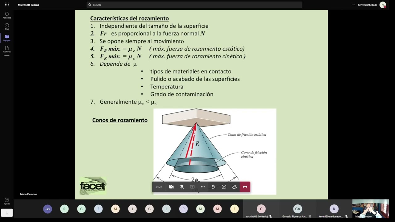
Clase teorica Mecanica Tecnica 27/05/22 16:15:17
428
When a body is about to slide at one support but pivots at another, the pivot point experiences no friction force (or friction below maximum). To analyze this case, take moments about the pivot point to eliminate the unknown friction force at that point. This simplifies the calculation and allows you to solve for the applied force required to initiate motion.
Click to watch →

Transmettre | Guidage en Rotation : Cours et Exercices d'application
103.7K
A pivot joint (liaison pivot) is a mechanical connection that enables rotational movement between two components while maintaining their relative orientation. Three technological solutions exist: shoulder joints with retaining rings, key and keyway systems, and threaded fasteners. Pivot joints are classified into three categories: direct contact between shaft and housing, bushing (coussinet) implementations, and rolling bearing systems. Direct contact pivot joints offer simple mounting but suffer from low power transmission capability, surface wear, and friction-related power losses. Bushings reduce friction by providing a bronze intermediary layer between contacting surfaces.
Click to watch →

Châssis pivot & Benne à pierres! SCRAP MECHANIC Let's build 2
6.9K
Friction between moving parts in articulated systems can cause binding and prevent smooth operation. To reduce friction, bearings (roulements) should be placed at pivot points where parts connect. The placement of bearings is critical - they should be positioned to allow free movement without creating new contact points that cause friction. When building articulated systems, always consider where friction will occur and plan bearing placement accordingly.
Click to watch →
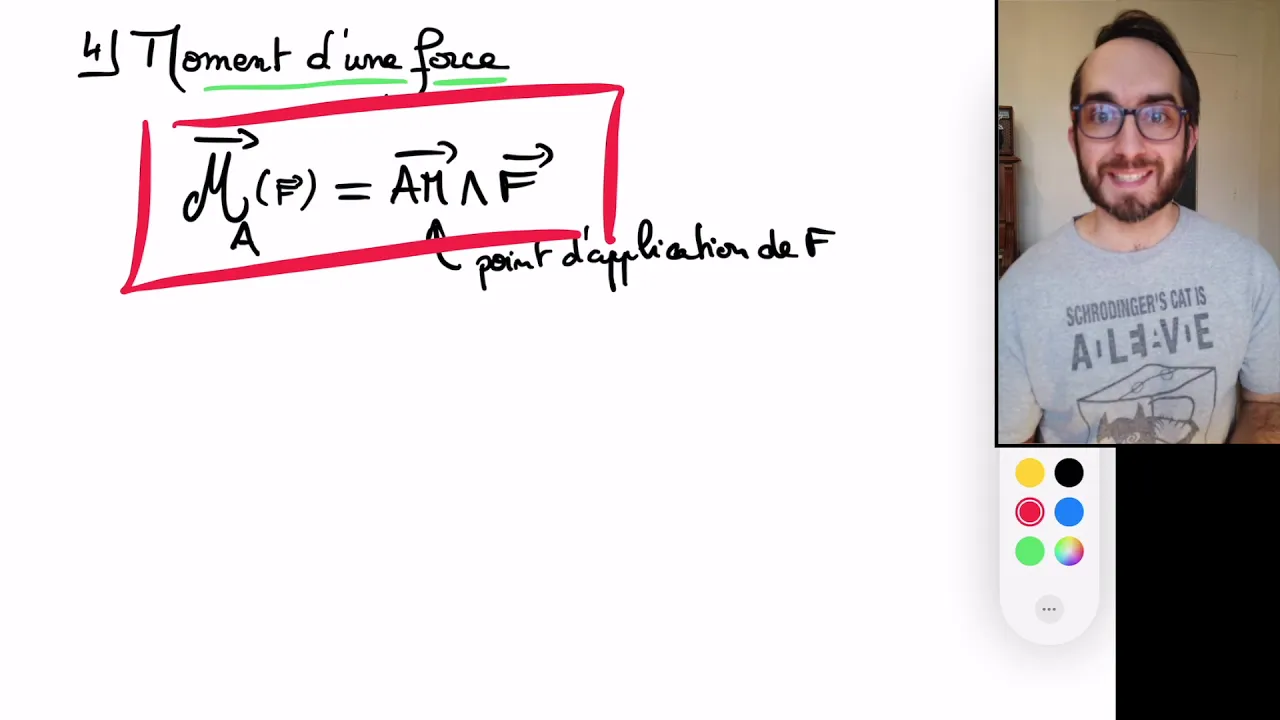
M6, parties I.4 à I.7, moment d'une force, couple, liaison pivot, moteur et frein
1.1K
Dans une liaison pivot imparfaite, les frottements se manifestent par des forces opposées qui s'exercent en différents points. Ces forces s'annulent globalement (résultante nulle) mais forment un couple résistant qui s'oppose à la rotation. Les frottements peuvent être modélisés de différentes façons : frottements solides (forces constantes) donnent un couple résistant constant, tandis que frottements fluides (proportionnels à la vitesse) donnent un couple résistant proportionnel à la vitesse angulaire. Pour une porte, les frottements solides donnent un couple constant, tandis que l'huile peut fluidifier les frottements.
Click to watch →
Prerequisite Knowledge
- Concept 01Basic understanding of simple machines, particularly levers and linkages, and how they transfer force.
- Concept 02Elementary geometry concepts, specifically the properties of parallelograms, rhombuses, and congruent triangles.
- Concept 03Concepts of structural forces such as tension, compression, and shear stress on materials.
- Concept 04The role of friction in pivot points and mechanical joints, and how it impacts moving parts.
Subsequent Learning
- Step 01Exploring different actuation methods, such as hydraulic, pneumatic, or motorized lead screw systems to power the lift.
- Step 02Calculating mechanical advantage and analyzing how the required input force changes at different heights and angles.
- Step 03Studying advanced planar kinematics and complex linkage systems, such as the Peaucellier-Lipkin or Klann mechanisms.
- Step 04Investigating industrial design standards, safety factors, and structural analysis of real-world aerial work platforms.
Shaving Practice
Two-Sided Work
Assistance Needed
Size Experiments
Final Alignment
Shaving Practice
0:07Playing Section
- 1
Starts hands-on shaving demonstration with pressure and blade dullness.
- 2
Encourages the participant, noting wood variations and blade technique.
- 3
Completes one side, acknowledging effort with applause.
Precision Modular Kits vs. Low-Cost Craft Materials in STEM
While building a scissor lift from popsicle sticks is highly accessible and budget-friendly, educators and engineers often highlight the limitations of using craft materials for mechanical engineering projects. Wood and glue introduce high friction, structural warping, and imprecise tolerances. These factors can cause mechanisms to jam or fail due to material defects rather than design errors, potentially frustrating students. Critics advocate for using precision-engineered modular kits (such as LEGO Technic, VEX, or 3D-printed components) instead. These systems provide consistent, repeatable results, allowing students to focus on the core physics of linkages, mechanical advantage, and structural design without the confounding variables of inconsistent materials.
Deep Dive
Exploring different actuation methods, such as hydraulic, pneumatic, or motorized lead screw systems to power the lift.

BUILD: Scissor Lift!
2.2M
Mechanical lift actuation converts rotational motion to linear force through threaded mechanisms. Cross nuts with sleeve bearings translate screw rotation into scissor mechanism movement, similar to car jack principles. Bearing retention prevents rotation while allowing free rotation of the actuating screw. Threaded rod actuators combine welded heads, hex drives, and jam nuts for reliable operation. The system demonstrates how simple mechanical principles can create powerful lifting capabilities, though screw-based systems have inherent travel limitations compared to hydraulic alternatives.
Click to watch →

Atuador Linear, Servo motor em Ação!
746
This segment compares three major actuation technologies. Pneumatic systems are excellent for simple movements with fixed courses but suffer from air compressibility causing position variations under load. Hydraulic systems excel at high forces (tons) and long courses but face challenges with heating, leakage, high maintenance, and complex control requirements. Servo linear actuators offer fine velocity control, position feedback through encoders, closed-loop operation, and excellent repeatability with simpler system complexity. The choice depends on application requirements for force, speed, precision, and maintenance considerations.
Click to watch →
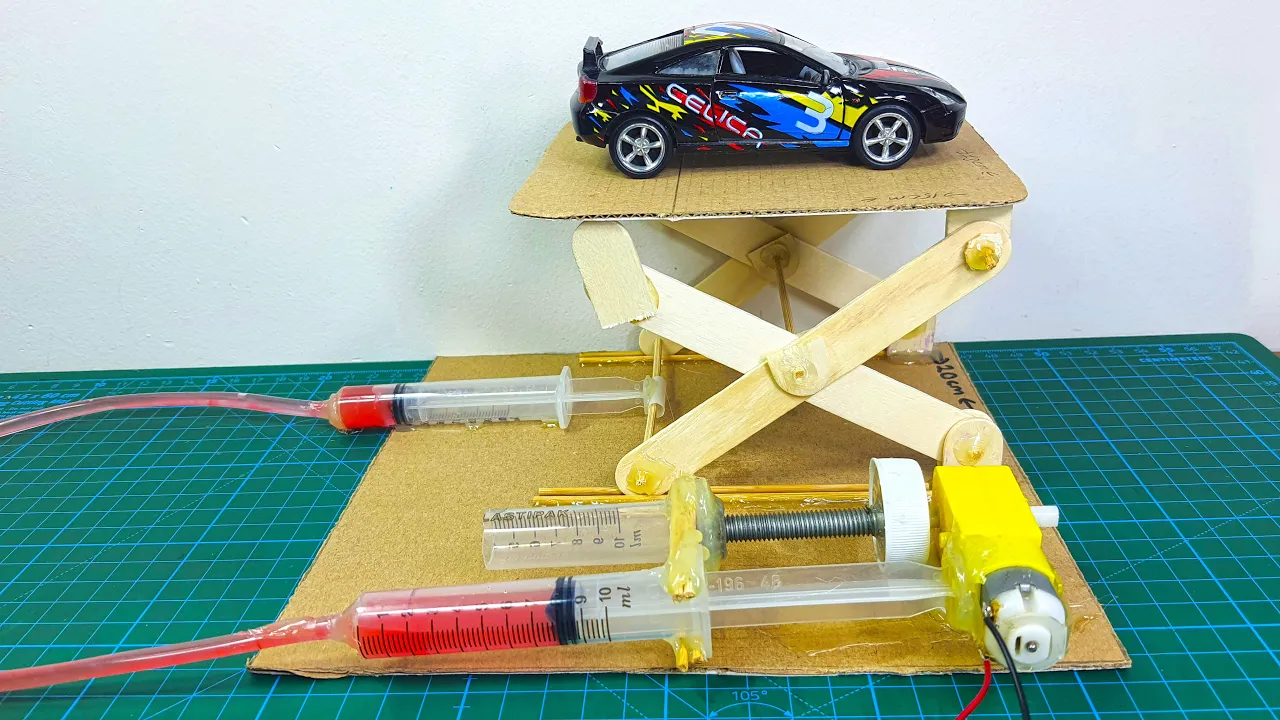
Car lifting - Hydraulic lift - Motorized lift #dcgearmotor #dcmotor #techexperiments
5.3K
A motorized hydraulic lift can be constructed using a DC gear motor connected to a hydraulic system with interconnected syringes, where the motor drives one syringe to push fluid into another, creating mechanical advantage that lifts objects; this demonstrates the principle of hydraulic pressure transmission where force applied to a small piston is multiplied across a larger piston area.
Click to watch →
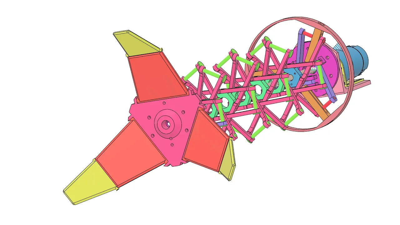
DIY Doc Ock Suit Pt. 1 | Designing a Collapsible Arm Mechanism
29.8K
A lead screw (also called an acme threaded rod) converts rotational motion into linear motion through a nut mechanism. In this extensor assembly, the motor drives the threaded rod, which pulls up on an acme nut attached to the mechanism. As the rod spins, it forces all connected links to rotate about their hexagonal hubs, causing the entire structure to extend. This design can achieve substantial extension (700mm demonstrated) while maintaining compactness, though joint intersections may occur at extreme extensions.
Click to watch →

Mechanically Multiplexed Flip-Dot Matrix
245K
A lead screw mounted on bearings drives a horizontal runner that moves up and down to position actuators. The motor drives the lead screw, which translates rotational motion into linear movement. Slots in 3D-printed plastic guide the movement and keep components aligned. This linear actuation system enables a single motor to address multiple positions along a path.
Click to watch →
Deep Dive
Calculating mechanical advantage and analyzing how the required input force changes at different heights and angles.

المستوى المائل - شرح مفصل 👌
50.5K
To find the height of an inclined plane: (1) Calculate weight from mass using W = m × g, (2) Apply the mechanical advantage formula: MA = L/h, (3) Rearrange to solve for h: h = L / MA. Example: For a 50 g object (0.5 kg, 5 N weight), MA = 4, and length = 4 m, the height is h = 4 / 4 = 1 meter. To find the applied force: F = (m × h) / L. Example: For a 50 g object (5 N weight), height = 1 m, and length = 4 m, the force is F = (5 × 1) / 4 = 1.25 N.
Click to watch →

الفيزياء الصف التاسع || جيل 2011 || الآلات البسيطة الجزء الأول || أ.محمود ابراش😍😍
46.6K
The inclined plane has two components: Length (along the surface) and Height (vertical distance). Mechanical Advantage (MA) can be calculated using two formulas: MA = Length/Height or MA = Load/Effort. The first formula is used when length and height are given, while the second is used when load and effort are given. MA is dimensionless because units cancel out. A higher MA means the inclined plane multiplies the force more effectively, making work easier to accomplish.
Click to watch →

Pulley Mechanical Advantage: Fixed, Movable, and Compound Systems
405.6K
Mechanical advantage (MA) is calculated as force out divided by force in, where force out is the force acting on the load and force in is the force applied to the machine; a fixed pulley has MA = 1 (no force reduction), while a movable pulley has MA = 2 (doubles the input force), and compound pulley systems can achieve much higher mechanical advantages by combining multiple pulleys.
Click to watch →

Correção ENEM 2016 - Física - Prof. Artur Neto
101.5K
A pulley system provides mechanical advantage by multiplying the input force. Each movable pulley doubles the force applied. The relationship is: Force_output = Force_input × 2^n, where n is the number of movable pulleys. To calculate the minimum number of pulleys needed to overcome static friction: (1) Calculate friction force = μ × Normal force, (2) Determine required output force to overcome friction, (3) Solve for n in the equation: 2^n = Required_force / Input_force. For a 3000 kg ship with μ = 0.8 and input force of 400 N, the friction is 24,000 N. Solving 2^n = 24,000/400 = 60 gives n = 6 (since 2^6 = 64 > 60).
Click to watch →

The Pulley - Simple Machines
352.3K
A pulley is a simple machine that provides mechanical advantage by multiplying the input force needed to lift an object; the mechanical advantage equals the number of ropes supporting the load, meaning the input force is divided among all supporting ropes while the output force equals the total weight, and this force multiplication comes at the cost of increased rope distance—pulling the rope twice as far allows lifting the object half the distance with half the force, while work remains conserved (input work equals output work).
Click to watch →
Deep Dive
Studying advanced planar kinematics and complex linkage systems, such as the Peaucellier-Lipkin or Klann mechanisms.

Peaucellier–Lipkin linkage 動態分析/Modeling and dynamic behavior analysis of Peaucellier–Lipkin linkage
107
The Peaucellier-Lipkin linkage is an 8-bar mechanism that converts reciprocating curved motion into reciprocating linear motion using only 3 different lengths of connecting rods, demonstrating a clever geometric solution for linear motion generation in mechanical engineering.
Click to watch →

mechanism with lower pairs - pantograph - peaucellier mechanism and straight line generators.
280
This section presents the Peaucellier-Lipkin mechanism, a jointed parallelogram with fixed link O1 and links O1A, O1C, O1D, AD, DB, and BC. The key parameters are AC = CB = BD = DA and O1A = O1C = O1D. Point A moves along a circle with OP as diameter, and point B traces a straight line perpendicular to OP. The proof uses the Pythagorean theorem on right triangles ORC and BRC to show that OC² - BC² = OR² - RB², which simplifies to OB × OA = constant. This mechanism is notable for being an exact straight line mechanism using only lower pairs.
Click to watch →

S4 KTU SURE SHOT QUESTION SERIES | MECHANICS OF MACHINERY | MODULE 1 | ONES
858
The Peaucellier-Lipkin mechanism generates exact straight-line motion using eight links. The condition requires that the product of distances from a fixed point to two points on the mechanism remains constant. This mechanism demonstrates how complex motion can be achieved through carefully designed linkages.
Click to watch →

Kinematics Ch02E Exact Straight Line Mechanisms
26.8K
The Paucellier mechanism (an 8-bar linkage) and Hart's mechanism (a 6-bar linkage) are exact straight line mechanisms that trace mathematically accurate straight lines through the principle of geometric inversion; in the Paucellier mechanism, four equal-length links form a rhombus with diagonals intersecting at right angles, and the product of distances from a fixed point to points on opposite sides remains constant, causing the inverse image to trace a straight line when the original point moves on a circle passing through the inversion center; similarly, Hart's mechanism uses a tracing point dividing a link in a specific proportion to achieve the same effect.
Click to watch →

STRAIGHT LINE MOTION AND PEAUCELLIER MECHANISM || TOM || VIDEO LECTURE || BY GAGAN BANSAL
7.2K
The Peaucellier mechanism is a linkage system that converts rotational motion into exact straight line motion using seven links and ten binary joints, with a degree of freedom of 1, where point P traces a straight path perpendicular to the fixed link when the product of distances OP × OQ remains constant.
Click to watch →
Deep Dive
Investigating industrial design standards, safety factors, and structural analysis of real-world aerial work platforms.
![[입문강의6강] 산업안전지도사 초보자 입문자를 위한 강의 - 차량계하역운반기계 편](https://i.ytimg.com/vi_webp/liSXto5B5ww/maxresdefault.webp)
[입문강의6강] 산업안전지도사 초보자 입문자를 위한 강의 - 차량계하역운반기계 편
4.2K
Aerial work platforms must meet five installation standards: (1) Safety factor of 5 when using wire rope or chain, (2) Ability to maintain position when using hydraulic systems, (3) Prevention of pressure abnormality, (4) Over-height prevention devices, (5) Ground stability to prevent tipping. These standards ensure platform stability during operation.
Click to watch →

Aerial Design Cases
110
Aerial device design requires adherence to multiple standards including NFPA 1901, 1983, 1989, and others, with tip load ratings determined by three key criteria: end user application (water flow, nozzle reactions, rescue operations), environmental conditions (wind loads, ice accumulation), and operational requirements (horizontal reach, outrigger spread). Manufacturers must account for nozzle reaction forces (approximately 505 lbs at 1000 GPM, 606 lbs at 1500 GPM), friction loss limits (not exceeding 100 PSI), and maintain a two-to-one structural safety factor while ensuring one-and-a-half-to-one stability safety factor. Equipment allowances typically range from 150-300 pounds depending on platform or ladder type, with counterbalance weight sometimes needed for stability. Modern materials like high-strength steel (100 ksi yield) enable lighter designs while maintaining safety requirements.
Click to watch →
![[46강] 26년 산업안전지도사 건설안전분야 안전기준](https://i.ytimg.com/vi/T8hAe3vHQyA/hqdefault.jpg)
[46강] 26년 산업안전지도사 건설안전분야 안전기준
191
When high-altitude work platforms are raised or lowered using wire ropes, chains, or hydraulic systems, employers must ensure: (1) the platform is designed to prevent falling if the lifting mechanism fails, (2) the safety factor is 5 or greater, (3) devices are installed to maintain constant position and prevent pressure fluctuations, (4) overload prevention devices are installed, (5) the platform's rated load capacity is 5 or greater, (6) guards or overload prevention devices are installed to prevent collision, and (7) operation switches have clear labels and directional indicators visible to operators.
Click to watch →
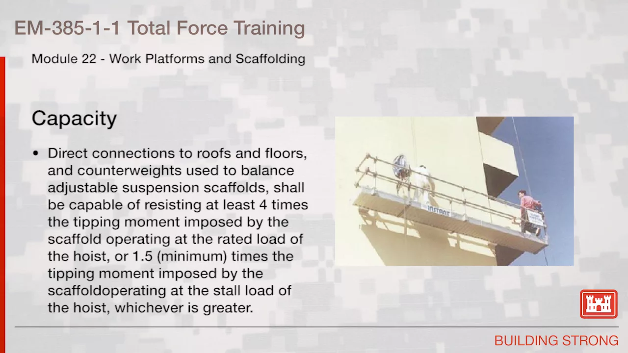
NAVFAC Safety Training Module 22: Work Platforms & Scaffolding
4.3K
Aerial work platforms (AWPs) including elevating aerial work platforms and vehicle-mounted elevating/rotating work platforms must comply with ANSI SI A92.3, SI A92.5, and SI A92.6 standards. Pre-operation surveys must assess work areas for hazards including soft ground, ditches, drop-offs, debris, overhead obstructions, and electrical conductors. Platforms must operate on firm level surfaces with loads within manufacturer specifications, using outriggers/stabilizers when required. Wheels must be locked or chocked. Lift controls must be below guardrail height or protected by aftermarket guards. Lower-level controls require permission from elevated workers except in emergencies. Only trained personnel may operate these platforms. Emergency egress plans for platforms 20+ feet high must include fall arrest equipment for all workers.
Click to watch →

산안기 필기 수식 39편 ㅣ 건설장비 수식기준 모음 (1) ㅣ #국가자격증 #산업안전기사 #인간공학기사 #산안기 #인공기 #국비교육
239
High-altitude work platforms are equipment designed for accessing elevated objects in factories, warehouses, or construction sites, requiring wire ropes or chains with a safety factor of 5 or greater, and cargo vehicles must have a cargo loading space height of at least 2 meters from the ground to the top surface.
Click to watch →
Shaving Practice
Two-Sided Work
Assistance Needed
Size Experiments
Final Alignment
Shaving Practice
0:07- 1
Starts hands-on shaving demonstration with pressure and blade dullness.
- 2
Encourages the participant, noting wood variations and blade technique.
- 3
Completes one side, acknowledging effort with applause.
Precision Modular Kits vs. Low-Cost Craft Materials in STEM
While building a scissor lift from popsicle sticks is highly accessible and budget-friendly, educators and engineers often highlight the limitations of using craft materials for mechanical engineering projects. Wood and glue introduce high friction, structural warping, and imprecise tolerances. These factors can cause mechanisms to jam or fail due to material defects rather than design errors, potentially frustrating students. Critics advocate for using precision-engineered modular kits (such as LEGO Technic, VEX, or 3D-printed components) instead. These systems provide consistent, repeatable results, allowing students to focus on the core physics of linkages, mechanical advantage, and structural design without the confounding variables of inconsistent materials.
Basic understanding of simple machines, particularly levers and linkages, and how they transfer force.
Elementary geometry concepts, specifically the properties of parallelograms, rhombuses, and congruent triangles.
Concepts of structural forces such as tension, compression, and shear stress on materials.
The role of friction in pivot points and mechanical joints, and how it impacts moving parts.
Exploring different actuation methods, such as hydraulic, pneumatic, or motorized lead screw systems to power the lift.
Calculating mechanical advantage and analyzing how the required input force changes at different heights and angles.
Studying advanced planar kinematics and complex linkage systems, such as the Peaucellier-Lipkin or Klann mechanisms.
Investigating industrial design standards, safety factors, and structural analysis of real-world aerial work platforms.
290.9K views548likes9:10@criminyjicketOriginal Release: 2009-04-15
[Music] cool all right down hard I am pressing down kind of hard but you know what okay [Music] I'm a little bit bigger than you and you know what um sometimes our blade may be getting dull too um it's all right okay got it cool you're doing fine I'm going to do this [Applause] [Applause] [Applause] okay niely done go ahead and do the other side now show I'm how to do both sides for [Applause] nice thank you I'm going to go over and continue PS okay keep your hands right where they are so people can see what you're doing please this one's too thick it won't go through uh just twist it and turn it they should all be the same size approximately they are wood and wood will do different things as it gets more uh humid but the nice thing is popsicle sticks or uh wood too one of the um popsicle sticks craft that's okay not a big for dad will you come help me sure kind of hard yes it is good next one you're doing fine [Applause] there you go see that's okay you can get something that you know makes you taller this Bucket over here be very careful with that bucket over there let's hope not is it playing yes it's [Music] recording that's wise move be oranges I lovewe they're good aren't they I wonder how small you can make it not terribly small probably break it'd be really cool if you could make it really small but it what's neat about it is that hm three oranges mhm what's cool about it is is that you can uh certainly make it much much larger can't you okay yeah yeah it's all good I just was having a hard time that sound's still alive it's a good thing I think we need you get some food most definitely there's some Goldfish food right there mhm so yeah get it for H can for uh not right now I use this dry Plank and stuff sure because our stuff is not lined up all that well um it won't uh it won't line up very well but it goes from how tall less than 6 in to well over a foot I want to make it
Up Next

94:54
Future of Astronomy Detectors: ESO & Caeleste Webinar
@caeleste7497
614 views•2025-06-10

30:32
Ultrasonic Transducers: Resonant Frequency Measurement and Horn Design
@imajeenyus42
229.9K views•2017-02-22

54:16
Polymer Environmental Degradation: Mechanisms & Stabilization
@iit
1.8K views•2012-07-10

33:39
How a Student's Question Saved a NYC Skyscraper from Collapse
@veritasium
22.8M views•2025-04-26
Related Study Plans & Knowledge Roadmaps
Structured learning paths in Engineering
engineering
Building Acoustic Levitators: Physics & Arduino
01The Physics of Sound and Standing Waves
02Piezoelectric Transducers and H-Bridge Drivers
03Arduino Programming: Generating 40 kHz Signals
+ 2 more learning modules
14h5 modules
Explore Roadmap
engineering
Building Peltier Cloud Chambers: Particle Tracks
01Cosmic Rays & Cloud Chamber Physics
02Thermoelectric Cooling (TEC) Fundamentals
03Custom Liquid-Cooling Loop Design
+ 2 more learning modules
18h5 modules
Explore Roadmap
engineering
Yagi-Uda Antennas: Modeling, Build & VNA Test
01Introduction to RF and Antenna Fundamentals
02Yagi-Uda Antenna Design Principles
03Antenna Modeling and Simulation in 4NEC2
+ 2 more learning modules
18h5 modules
Explore Roadmap
engineering
ECG Monitor Design: Op-Amps, Filters & Noise
01Electronics & Breadboard Basics
02Op-Amps and Instrumentation Amplifiers
03Bioelectricity and ECG Fundamentals
+ 2 more learning modules
18h5 modules
Explore Roadmap