An Automated Guided Vehicle (AGV) is an autonomous mobile robot that uses microcontroller-based systems with sensors (RFID for path/goods detection, ultrasonic for obstacle avoidance, load cell with ADC for weight measurement) and communication modules (GSM modem) to navigate, transport goods, and send automated alerts for events like overload, object detection, destination arrival, and wrong goods identification.
Embedded C Based Automated Guided Vehicle for Industrial Automation
Added:Deep Dive
Fundamentals of Embedded C programming, including register-level configuration, interrupt service routines (ISRs), and memory management.

COMPLETE EMBEDDED SYSTEMS Roadmap - What Arduino Won't Teach You
62.5K
C programming is the foundation of embedded systems development. Unlike system C (socket programming, multi-threading on Linux), embedded C means your code is the only thing running on the system, giving full control over CPU operations including hardware interrupts. Essential concepts include if/else statements, switch cases, while loops, pointers, structs, and unions. Critical data types are unsigned integers (uints) and bit masks, which are fundamental in embedded devices. Understanding bits and bit manipulation is essential since embedded work often requires working at the bit level rather than byte level.
Click to watch →
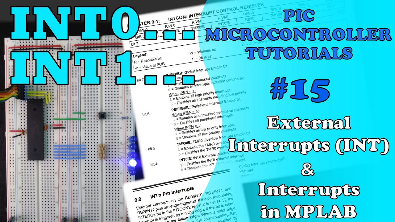
PIC MCU TUTORIALS #15 - External Interrupts (INT) & Interrupts in MPLAB (Absolute Beginner)
9.9K
Interrupt Service Routines (ISRs) are special functions declared with the __interrupt specifier in XC8 C. The syntax is void isr_name(void) __interrupt [priority_level], returning void since hardware interrupts don't return values. ISRs handle interrupts by jumping to a predefined vector address. The compiler manages register saving and restoration. Priority levels are specified as high_priority or low_priority; if unspecified, it defaults to high priority. After handling an interrupt, the corresponding flag bit must be manually cleared before exiting, or the microcontroller will re-enter the ISR infinitely.
Click to watch →

Embedded System Design Session 2
160
This extensive section establishes the complete embedded C programming foundation. It covers project setup in CodeVision including selecting microcontroller models (ATmega328P), configuring clock frequencies (8MHz for 3.3V), and generating initialization code. The main function structure uses void main() with no arguments since embedded systems lack operating systems, featuring an infinite while loop to prevent garbage code execution. Header files define symbolic names for register addresses using #define directives, improving code readability. The section introduces interrupt handling mechanisms including the interrupt vector table mapping sources to service routines, stack-based context saving, and priority levels. External interrupts (INT0, INT1) trigger on specific pins while pin change interrupts monitor groups of pins. USART interrupt disable (UCSRB = 0x00) demonstrates peripheral reconfiguration. Global variable declaration, volatile keyword for interrupt safety, and delay functions complete the practical programming toolkit essential for embedded development.
Click to watch →
Embedded C Basics:Key Concepts Explained
434
Embedded C is a specialized version of C designed for programming microcontrollers and embedded systems, enabling direct hardware access through memory-mapped registers. Key concepts include using fixed-width types (UINT8, UINT32) for portability, applying volatile keyword to prevent compiler optimization of hardware registers, mapping peripheral registers using structs with volatile members, and implementing efficient interrupt service routines. Understanding memory layout, structure padding, and alignment is crucial for optimizing resource-constrained environments. The startup process involves initializing the stack, setting up memory sections, and jumping to the main function, while debugging requires using volatile flags, hardware timers, and keeping ISRs minimal.
Click to watch →

Fundamentos de lenguaje C para sistemas Embebidos clase 2/7
2K
Embedded systems programming differs from general computer programming in structure and purpose. The main() function serves as the entry point and typically runs in an infinite loop, while interrupt service routines (ISRs) handle hardware events. The main() function can return an integer value, while ISRs are typically void functions. The instructor demonstrates basic input/output using scanf with format specifiers like %d for integers and %c for characters, showing how to read user input and display results. Understanding this structure is essential for developing efficient embedded applications that respond to hardware events while maintaining overall system coordination.
Click to watch →
Deep Dive
AVR microcontroller architecture (e.g., ATmega328P or ATmega16) and control of peripheral interfaces like GPIOs, Timers, and PWM.

ATmega328P
3.1K
The ATmega328P is an 8-bit RISC microcontroller with 28 pins, 131 instructions, and 32 general-purpose 8-bit registers. It operates at up to 20 MHz with Harvard architecture enabling pipelining. Memory includes 32KB flash for programs, EEPROM for data (100K write cycles), and RAM for variables. The memory map reserves the first 32 addresses for register mapping. Peripherals include 23 I/O pins across three ports, 12 8-bit timers (two 16-bit), 16 PWM channels, 8-channel 10-bit ADC, and three serial protocols (I2C, SPI, UART). Clock sources include internal RC oscillator (up to 8 MHz), external crystal (up to 20 MHz), or external clock. All peripherals require clock signals and can be configured through frequency multiplication or division.
Click to watch →

HackadayU: AVR: Architecture, Assembly & Reverse Engineering Class 1
19K
The AVR microcontroller architecture features two distinct memory spaces—program memory and data memory—which is fundamentally different from architectures like Intel or ARM that use a unified address space. This separation explains why variables and functions can share the same numerical address but belong to different memory spaces. For GPIO control, each port (B, C, D) has three key registers: DDRxn (Data Direction Register) to configure pins as input or output, PORTxn to set output values or toggle pins, and PINxn to read input values or trigger toggles. Writing logic 1 to PINxn toggles the corresponding PORTxn bit regardless of DDRxn settings. External interrupts are managed through registers like EIMSK and EICRA, with ISRs defined using the ISR() macro. Timers count clock cycles and generate interrupts on overflow, enabling precise timing applications.
Click to watch →

AVR Mikrokontrolcülerin Temel Çalışma Prensibi, Hafıza Adresleme ve AVR Komut Seti #6
14.1K
Microcontrollers from different manufacturers share fundamental working principles, making understanding internal architecture essential before programming. The ATmega328P is an 8-bit microcontroller with 131 instructions, operating up to 20 MHz. It includes 32KB flash memory (10,000 write cycles), 1KB EEPROM (1,000 write cycles), and 2KB RAM. Key peripherals include two 8-bit timers, one 16-bit timer, 10-bit ADC, USART, SPI, and I2C interfaces. Memory is organized using hexadecimal addressing with four types: Flash program memory (read-only), Working Registers (temporary processing), RAM (volatile data), and EEPROM (non-volatile storage). Clock systems use crystal oscillators measured in Hertz, with options including internal RC oscillators (128 kHz, 8 MHz) and external crystals. Internal RC oscillators vary with temperature and voltage, making external crystals preferable for precise timing.
Click to watch →
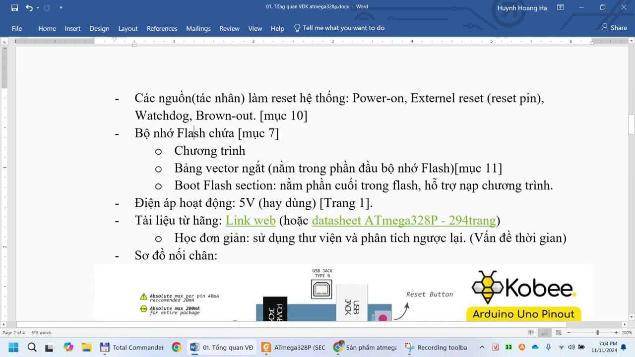
Giới thiệu VĐK Atmega328P (AVR)
1.6K
The AT Mega 328P is an 8-bit AVR microcontroller featuring a CPU with ALU, Control Unit, and 32 general-purpose registers, three types of memory (SRAM for data processing, EEPROM for non-volatile data storage, and Flash for program storage), and various peripheral modules for external communication including timers, ADC, and I/O ports. It operates at frequencies up to 16-20 MHz with a 5V power supply and is commonly used in Arduino Uno boards for embedded system development.
Click to watch →
![[임베디드 기초 뿌수기 5-1] 임베디드의 시작, GPIO란?](https://i.ytimg.com/vi_webp/HD4nXj2Dm5k/maxresdefault.webp)
[임베디드 기초 뿌수기 5-1] 임베디드의 시작, GPIO란?
1.1K
GPIO (General Purpose Input Output) is the fundamental MCU function enabling signal exchange with external devices. ATmega328P organizes GPIO into three ports: Port B (8 pins), Port C (7 pins), and Port D (8 pins). Pins have special functions: PC6 as reset, PB0-PB2 for SPI SCLK, RXD/TXD for UART, INT0/INT1 for interrupts, AIN0/AIN1 for comparators, and ADC0-ADC5 for conversion. However, ATmega328P has only one ADC handling one conversion at a time. Configuration is achieved through register manipulation, with MCUCR at 0x55 containing control bits for interrupt vectors and brown-out detection.
Click to watch →
Deep Dive
Basic serial communication protocols, particularly UART (Universal Asynchronous Receiver-Transmitter) used by RFID and GSM modules.
Embedded Systems Protocols Serial-UART I2C SPI Communication
70.3K
UART (Universal Asynchronous Receiver Transmitter) is a fundamental serial communication protocol used extensively in embedded systems. It enables communication between microcontrollers and various peripheral devices such as GPS modules, GSM modules, Bluetooth modules, RFID modules, PLCs, and CNC machines. UART operates asynchronously without a shared clock signal between devices, using a frame structure that includes start bits, stop bits, and data bits (typically 8-bit ASCII characters). The protocol uses TX and RX pins for full-duplex communication where one device transmits while the other receives. UART is particularly valuable for debugging purposes, allowing engineers to monitor sensor data collected by microcontrollers on a personal computer through USB-to-serial adapters and terminal software.
Click to watch →

PROTOCOLS UART I2C SPI Serial communications
568
UART (Universal Asynchronous Receiver/Transmitter) is the most basic asynchronous serial communication protocol. It uses one data wire (TX for transmitter, RX for receiver) plus ground. Three configuration parameters must match between devices: transmission speed (Baud rate, commonly 9600 bits/second), data length (typically 8 bits), and start/stop bits. The start bit (low pulse) signals the receiver to begin reading, while the stop bit (high pulse) marks the end. The receiver samples data at the middle of each bit period to ensure accurate reading. RS232 is a UART variant used by older computers with additional flow control pins (DTR, CTS) for preventing data loss.
Click to watch →
UART | SPI | I2C | Embedded System Protocols MCQ by kaushik classes
178
UART (Universal Asynchronous Receiver Transmitter) is a fundamental serial communication protocol used in embedded systems. It supports three communication modes: Simplex (one-way), Half-Duplex (alternating two-way), and Full-Duplex (simultaneous two-way). The protocol uses a shift register to convert serial data to parallel format. Data detection relies on a local clock reference, with the TxD pin set to high when idle and low when transmitting. The baud rate, measured in bits per second, defines the transmission speed and is generated through an external timer. UART is commonly used for GSM modules operating at 900 MHz and 800 MHz frequencies.
Click to watch →
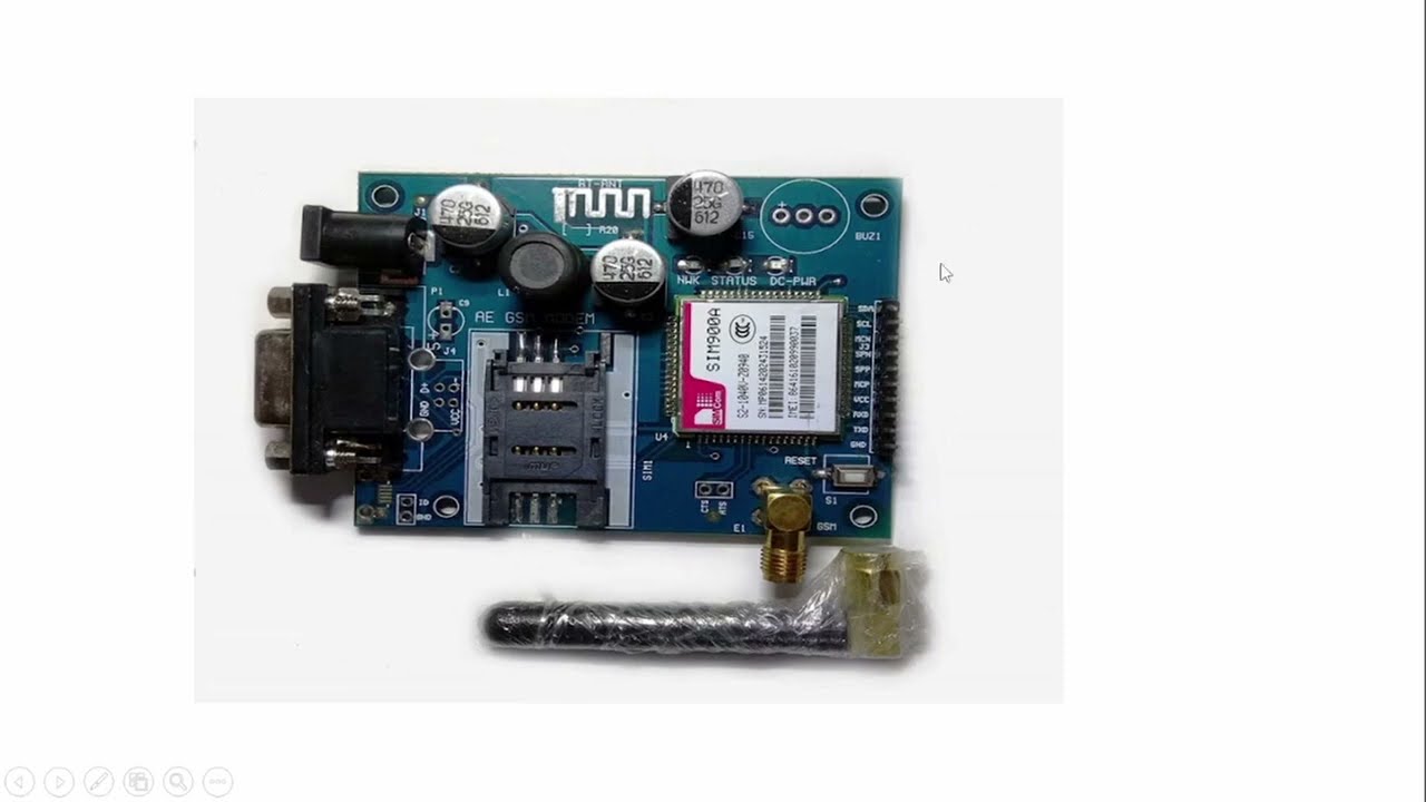
GSM Module Magic: Make Calls & Send SMS with microcontroller
251
GSM modules communicate via UART requiring TX, RX, and ground pins. AT commands (a set of approximately 80 standardized commands) serve as the control language for GSM modules, instructing them to perform actions like making calls or sending messages. The basic 'AT' command tests module connectivity, returning 'OK' when successful. Communication typically uses serial terminals like PuTTY or Arduino as intermediaries between the computer and GSM module. The Arduino forwards data bidirectionally between the PC and GSM module, allowing users to send commands and view responses without writing complex code.
Click to watch →

Очередные модули из Китая #3
14.4K
This video demonstrates three types of electronic modules: a digital infrared thermometer (MLX90614) with I2C and PWM interfaces measuring temperatures from -70°C to +380°C with ±0.5°C accuracy at 0-50°C; an RFID reader (MFRC-522) supporting SPI, I2C, and UART interfaces for reading RFID tags; and a GSM module kit (NEOWAY M590) with SIM holder, LEDs, and resistors, controlled via UART AT commands and supporting GPRS Class 10. These modules are commonly used in electronics projects and hobbyist applications.
Click to watch →
Deep Dive
Principles of sensor interfacing, specifically calculating distance using ultrasonic sensor trigger/echo pulses and reading RFID tag data.

Ultrasonic sensor interfacing by Navyasree
362
Ultrasonic sensors measure distance by emitting sound waves through the Trig pin and calculating the distance based on the time it takes for the Echo pin to receive the reflected signal, using the formula: distance = (speed of sound × time) / 2.
Click to watch →

Lesson - 11: How to Use HC-SR04 Ultrasonic Sensor with Arduino | pulseIn() Explained
1K
The HC-SR04 ultrasonic sensor measures distance by emitting 40kHz sound pulses and measuring the echo return time; to interface it with Arduino, connect VCC to 5V, GND to ground, trigger to a digital output pin, and echo to a digital input pin, then use the pulseIn() function to read the echo pulse width and calculate distance using the formula distance = (duration × 0.034) / 2, where duration is in microseconds and 0.034 cm/μs represents the speed of sound.
Click to watch →

O Level M4-R5 IoT Practical LIVE Class | Class - 22 July | Arduino Practical & Viva | By Ravi Sir
472
This segment explains the ultrasonic sensor trigger mechanism: setting Trig pin to LOW for 2 microseconds, then HIGH for 10 microseconds to send pulses. The Echo pin returns pulse duration using pulseIn() function. The distance calculation formula is: Distance = (Time × Speed of Sound) / 2, where speed of sound is approximately 340 m/s. The division by 2 accounts for the round-trip travel of sound waves.
Click to watch →
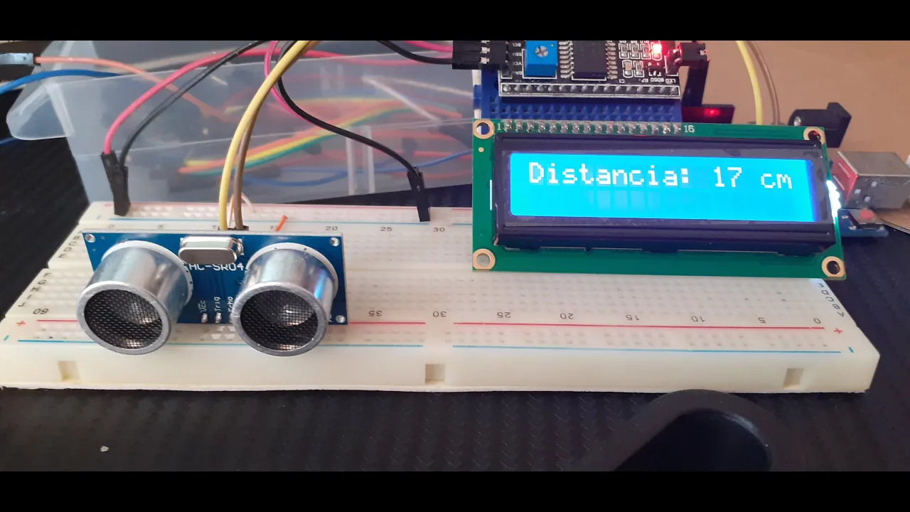
Crea un medidor de distancia con el sensor HC-SR04, Arduino UNO R3 y una Pantalla LCD
226.4K
This section details the complete trigger sequence for the HC-SR04 sensor. The process involves: (1) Setting TRIG_PIN to LOW and delaying 2 microseconds, (2) Setting TRIG_PIN to HIGH and delaying exactly 10 microseconds (minimum required), (3) Setting TRIG_PIN back to LOW, (4) Reading the ECHO_PIN using pulseIn() to measure the duration of the returning pulse. The pulse duration represents the time taken for the ultrasonic wave to travel to the object and return. This precise timing sequence is critical for accurate distance calculations.
Click to watch →
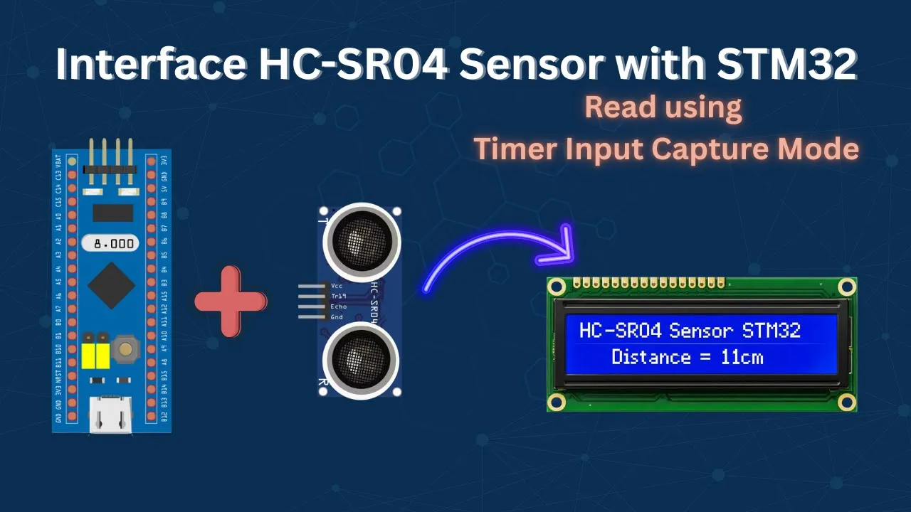
Interface HC-SR04 Ultrasonic Sensor with STM32 | Input Capture Tutorial
55.6K
This section covers the complete workflow for triggering the HC-SR04 sensor and calculating distance. To trigger the sensor, the trigger pin must be pulled high for approximately 10 microseconds using a dedicated microsecond delay function, then pulled low. The sensor emits an ultrasonic burst and waits for the echo. The distance is calculated using the pulse width measured from the echo: distance = (pulse width × speed of sound) / 2. The implementation includes periodic polling every 200 milliseconds to prevent overwhelming the system. Error handling is demonstrated, including debugging common issues like incorrect pin definitions and missing header files.
Click to watch →
Prerequisite Knowledge
- Concept 01Fundamentals of Embedded C programming, including register-level configuration, interrupt service routines (ISRs), and memory management.
- Concept 02AVR microcontroller architecture (e.g., ATmega328P or ATmega16) and control of peripheral interfaces like GPIOs, Timers, and PWM.
- Concept 03Basic serial communication protocols, particularly UART (Universal Asynchronous Receiver-Transmitter) used by RFID and GSM modules.
- Concept 04Principles of sensor interfacing, specifically calculating distance using ultrasonic sensor trigger/echo pulses and reading RFID tag data.
Subsequent Learning
- Step 01Advanced autonomous navigation techniques, such as SLAM (Simultaneous Localization and Mapping) and the integration of LiDAR or computer vision.
- Step 02Introduction to ROS (Robot Operating System) for high-level path planning, localization, and fleet coordination.
- Step 03Industrial communication protocols (like CAN bus or Modbus) to integrate the AGV into a broader factory automation ecosystem (PLC/SCADA).
- Step 04Transitioning from GSM to modern IoT protocols (such as MQTT over Wi-Fi/4G) to push load-monitoring telemetry to cloud platforms for real-time analytics.
System Setup
Load Check
Delivery Done
System Setup
0:00Playing Section
- 1
Introduces AGV hardware including microcontroller, motors, and sensors.
- 2
Details power supply conversion from lead-acid battery.
Autonomous Mobile Robots (AMRs) with SLAM and ROS vs. Traditional Microcontroller-Based AGVs
While low-level, microcontroller-based AGVs utilizing RFID and ultrasonic sensors are cost-effective for basic educational setups, they are increasingly obsolete in modern industrial environments. Industry 4.0 heavily favors Autonomous Mobile Robots (AMRs) driven by powerful Single Board Computers (SBCs) running the Robot Operating System (ROS) and Simultaneous Localization and Mapping (SLAM). Unlike rigid, infrastructure-dependent RFID AGVs, SLAM-enabled AMRs dynamically map and navigate factories without physical markers, using LiDAR and computer vision instead of basic ultrasonic sensors. Furthermore, bare-metal Embedded C on 8-bit microcontrollers (like AVR) lacks the computational power, safety certifications (e.g., ISO 13849), and multi-threading capabilities required for complex industrial sensor fusion. For telemetry, legacy GSM is being phased out globally, replaced by high-bandwidth, low-latency technologies like Wi-Fi, 5G, or private LoRaWAN. Consequently, modern industrial automation prioritizes robust Programmable Logic Controllers (PLCs) and ROS-based AMRs over hobbyist-grade microcontroller architectures.
Deep Dive
Advanced autonomous navigation techniques, such as SLAM (Simultaneous Localization and Mapping) and the integration of LiDAR or computer vision.

SLAM и архитектуры моделей компьютерного зрения в автономных транспортных средствах //
423
SLAM (Simultaneous Localization and Mapping) enables autonomous vehicles to simultaneously determine their position while building a map of an unknown environment, using three main algorithmic approaches: Extended Kalman Filter (EKF) for linear Gaussian problems, Particle Filter for non-linear non-Gaussian scenarios, and Graph-Based Optimization for global trajectory refinement; these algorithms process sensor data from cameras, LIDAR, and IMUs to achieve robust navigation in autonomous systems.
Click to watch →

So schlau ist der Navimow i2 wirklich… (3D-Karte, LiDAR,Kanten + KI)
2.8K
LIDAR (Light Detection and Ranging) enables autonomous navigation through laser-based distance measurement. The system emits laser beams and calculates distances by measuring return time, achieving millimeter precision. Combined with camera-based image analysis, this multi-sensor fusion creates comprehensive environmental awareness. The technology identifies objects as small as chair legs or hammer handles with centimeter-level accuracy and operates effectively in darkness. Safety functions include collision avoidance to prevent damage to property and protect living beings. This integration of LIDAR and computer vision represents the core technology enabling truly autonomous lawn maintenance.
Click to watch →

Autonomes Fliegen und Flugtaxis
253
SLAM (Simultaneous Localization and Mapping) enables autonomous systems to create accurate environmental models in unknown, GPS-degraded environments. SLAM techniques divide into filtering (estimation from recent measurements) and smoothing (considering all past measurements). Sensor technologies include Lidar for obstacle distance measurement, odometry for path characterization, and visual methods comparing captured images to calculate transformations. These sensors provide the data foundation for autonomous navigation, with visual methods being particularly common in aviation for capturing and comparing environmental images to determine movement between capture times.
Click to watch →

Flavors of SLAM: vSlam vs LIDAR
4.9K
SLAM (Simultaneous Localization and Mapping) integrates inertial sensors with vision/light sensors for robot navigation. LiDAR, a light-based ranging technology, emits laser pulses and measures return times to calculate distances, creating detailed 3D environmental maps. Visual SLAM extracts key features like corners and edges from camera streams for geometric matching. LiDAR operates similarly to radar but uses light, with two main types: solid-state (no moving parts) and rotating (spinning laser arrays). Major autonomous vehicle companies including Waymo, Uber, Ford, and GM employ LiDAR systems for real-time environmental perception and obstacle detection.
Click to watch →
20190106 Introduction to SLAM
13.6K
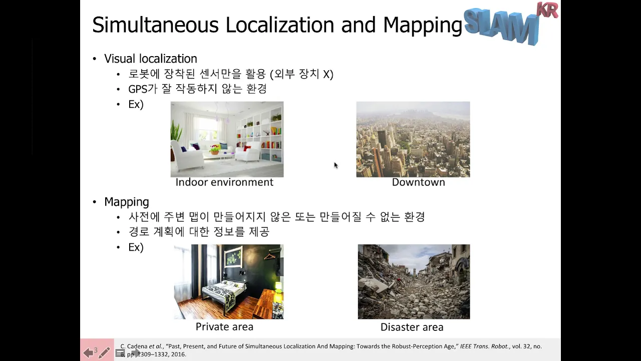
SLAM (Simultaneous Localization and Mapping) enables robots to navigate freely in unknown environments by solving two interdependent problems: localization (determining position) and mapping (understanding the environment). This 'chicken-and-egg' problem requires simultaneous solution. Visual SLAM uses onboard sensors like cameras without external assistance, making it valuable for GPS-denied environments like indoors, urban canyons, or disaster areas. Three main sensor types exist: monocular cameras (simple, low computational cost but no scale information), stereo cameras (accurate depth with fixed baseline but computationally intensive), and depth cameras (accurate 3D measurements but limited range and field of view). LiDAR sensors measure depth by calculating laser pulse time-of-flight, generating high-resolution 3D point clouds suitable for autonomous vehicles. Traditional Visual SLAM systems follow a structured architecture: sensor input processing, frontend motion estimation, backend optimization, loop closure detection, and map generation. The frontend processes consecutive frames to estimate camera motion, requiring calculations of rotation and translation between viewpoints. This motion estimation is fundamental but introduces drift errors that accumulate over time. Back-end optimization addresses accumulated drift errors using loop closure information, identifying when the robot returns to previously visited locations to globally optimize the trajectory. Two main approaches exist: filter-based methods (Kalman Filters, Particle Filters) and optimization-based methods (Bundle Adjustment, Pose Graph Optimization). Optimization-based methods have become dominant due to improved computing power and the ability to exploit sparsity. Map representation methods include Point Cloud Maps (3D points), Octree Maps (hierarchical voxel structures), and Sparse Maps (significant features only). Sparse SLAM extracts key features and matches them across frames using triangulation, offering low computational requirements. Dense SLAM processes all pixels to create comprehensive environmental maps, requiring GPU parallel processing. Semi-dense SLAM processes only edge regions, capturing structural information while maintaining computational efficiency. LSD-SLAM enables real-time dense mapping in large-scale environments through direct methods and sparsity exploitation. LiDAR SLAM uses LiDAR sensors for simultaneous localization and mapping, with algorithms like LOAM being prominent. Unlike visual SLAM, LiDAR SLAM does not require loop closure detection because LiDAR provides direct geometric measurements with high precision. The point cloud data contains clear geometric features enabling accurate pose estimation.
Click to watch →
Deep Dive
Introduction to ROS (Robot Operating System) for high-level path planning, localization, and fleet coordination.

An introduction to ROS the Robot Operating System
20.8K
ROS (Robot Operating System) is an open-source meta-operating system for robots that provides hardware abstraction, device control, message passing, and package management, enabling efficient development through standardized communication protocols and collaborative frameworks; it operates on multiple levels including the file system level (packages, manifests, repositories) and the computational graph level (nodes, master, parameter server, topics, services, bags), with key concepts including publish-subscribe messaging for asynchronous communication and request-reply services for time-critical operations, all supported by community resources like the ROS wiki, mailing lists, and distribution systems.
Click to watch →
An Introduction to ROS, the Robot Operating System: Intro to ROS (2/6)
93.4K
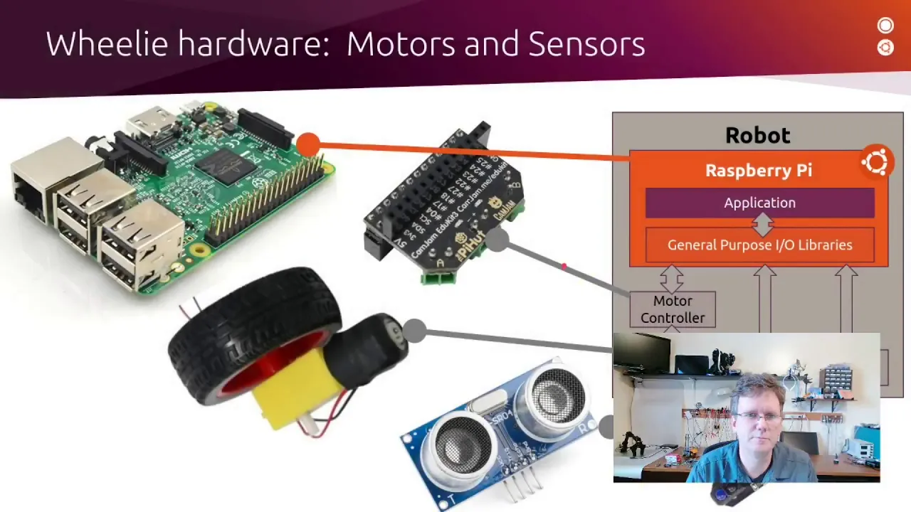
ROS (Robot Operating System) is an open-source middleware framework that provides standardized communication constructs—nodes, topics, services, and actions—to enable collaboration between different robot components and software applications, facilitating the development of robots that operate alongside humans in mainstream environments.
Click to watch →

An Introduction to ROS, the Robot Operating System: Introduction (1/6)
13.8K
ROS (Robot Operating System) is an open-source framework for writing robot software that enables communication between different robot components through nodes connected by topics, services, and actions, allowing developers to build complex robotic systems by combining hardware control, sensor integration, and high-level functionality in a modular architecture.
Click to watch →
Introduction to Path Planning in Robot Operating System (ROS)
22.3K
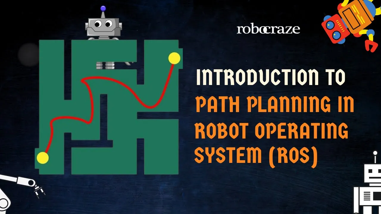
This video introduces path planning in robotics using ROS (Robot Operating System) and Gazebo simulation, demonstrating how robots autonomously navigate from starting points to desired locations by identifying optimal routes while avoiding obstacles in both indoor and outdoor environments.
Click to watch →

What is ROS (short description)
29.2K
ROS (Robot Operating System) is an open-source programming framework for robotics developed in the late 2000s at Stanford University and Willow Garage. Before ROS, robotic software was proprietary and highly specialized, requiring developers to reinvent solutions for each project. ROS addresses common challenges including coordinate system transformations, motion planning, communications, and sensor integration. It enables modular software development through reusable code packages, provides a runtime environment for near real-time communication, offers development tools for monitoring and visualization, and supports computer simulations for robot behavior tuning.
Click to watch →
Deep Dive
Industrial communication protocols (like CAN bus or Modbus) to integrate the AGV into a broader factory automation ecosystem (PLC/SCADA).

New technologies for AGVs-PLCnext Technology makes it possible: Engineering, safety & communication
127
AGVs have evolved from automotive serial production to essential intralogistics components. The next generation requires cost reduction, performance improvement, reduced downtime, and better maintenance. A major challenge is consolidating three separate systems (navigation, control, safety) into unified architectures. PLC Next technology integrates these components into a single engineering platform, supporting open protocols (Profinet, EtherCAT, Modbus) over proprietary systems. Protocol consolidation reduces wiring complexity and eliminates protocol selection decisions. Additionally, the Cyber Resilience Act (CRA) requires comprehensive cyber security measures by end of 2027, with penalties up to 15 million euros or 2.5% of annual turnover. Compliance requires a 360-degree approach covering product development, service, patches, and consulting to ensure stable, secure AGV fleet operations.
Click to watch →

PLC con ARDUINO (ATMEGA2560) V5, CON 24 ENTRADAS, 16 SALIDAS IGBT CIRCUIT BASADO en el PLC SIEMENS
195.7K
The PLC integrates Modbus protocol, which is the most predominant and standard communication protocol in industrial environments due to its high reliability. The NSC 28-J60 circuit interface enables data transmission between the microcontroller and external devices, facilitating reliable industrial communication.
Click to watch →
QtWS16- Qt Serial Bus: Using Modbus and CAN bus with Qt, Jeff Tranter, ICS
7.1K
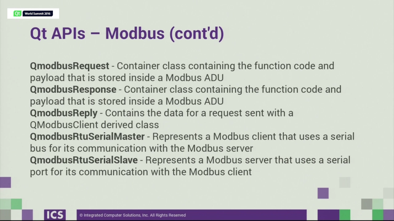
This section covers two fundamental industrial serial bus protocols. CAN (Controller Area Network), developed by Bosch, enables multi-master communication over a two-wire twisted pair bus at speeds up to 1 Mbps within 40 meters, widely used in automotive systems since 1996 with OBD-II connectors providing access. Modbus, originating from Modicon in the 1970s for PLC applications, uses a master-slave architecture with unique device addresses and supports coils, contacts, input registers, and holding registers over serial or Ethernet TCP port 502. Both protocols enable distributed device communication without centralized hosts, forming the backbone of modern industrial automation and vehicle electronics.
Click to watch →
Chapter 03_PLC Communication Protocols_##PLC Learning for Beginners##
383
PLC communication protocols are standardized methods that enable devices in industrial automation systems to exchange data and commands, functioning like conductors that coordinate the operation of various devices such as PLCs, HMIs, SCADA systems, sensors, and actuators; common protocols include Modbus (master-slave architecture), Profibus (high-speed for manufacturing), Ethernet/IP (real-time control over Ethernet), DeviceNet (CAN-based for simple device control), Profinet (industrial Ethernet with real-time capabilities), and EtherCAT (real-time synchronized control), with the optimal protocol selection depending on specific application requirements, network infrastructure, device compatibility, and PLC capabilities.
Click to watch →

Redes de comunicación Industrial y Automatización
128
Controller Area Network (CAN) and related protocols (CANopen, DeviceNet, EtherCAT) support master-slave or producer-consumer communication architectures for industrial control systems. These protocols enable structured information exchange, program loading, diagnostics, and execution coordination between PLCs, robots, and CNC systems. Sensor and actuator networks connect field devices (encoders, temperature sensors, pressure sensors, variable frequency drives, servo valves) directly to higher-level control systems, enabling configuration, calibration, and programming from centralized locations. Multiple fieldbus protocols exist due to varying application requirements: device counts per segment range from 8-32 to hundreds, and communication distances vary from 10-20 meters to 200+ meters. RS series standards (RS-232, RS-422, RS-485) define serial communication electrical characteristics. Major industrial protocols (Foundation Fieldbus, ControlNet, PROFIBUS, Interbus, DeviceNet) have achieved standardization through organizations like ISA and IEC.
Click to watch →
Deep Dive
Transitioning from GSM to modern IoT protocols (such as MQTT over Wi-Fi/4G) to push load-monitoring telemetry to cloud platforms for real-time analytics.

GSMGate. Шлюз для IoT екосистеми від компанії "Церта"
323
GSMGate is a programmable protocol converter that transforms Modbus RTU data from connected equipment into MQTT protocol for transmission over mobile networks, enabling remote monitoring and control of up to 2056 Modbus registers through an MQTT broker, with applications in climate control systems for food processing, retail centers, and administrative buildings.
Click to watch →

Publicando dados na Nuvem com ESP32 e MQTT
6.1K
This tutorial demonstrates how to publish sensor data from an ESP32 microcontroller to the cloud using the MQTT (Message Queuing Telemetry Transport) protocol, enabling remote monitoring and control of IoT devices such as lamps and electrical loads through mobile applications.
Click to watch →
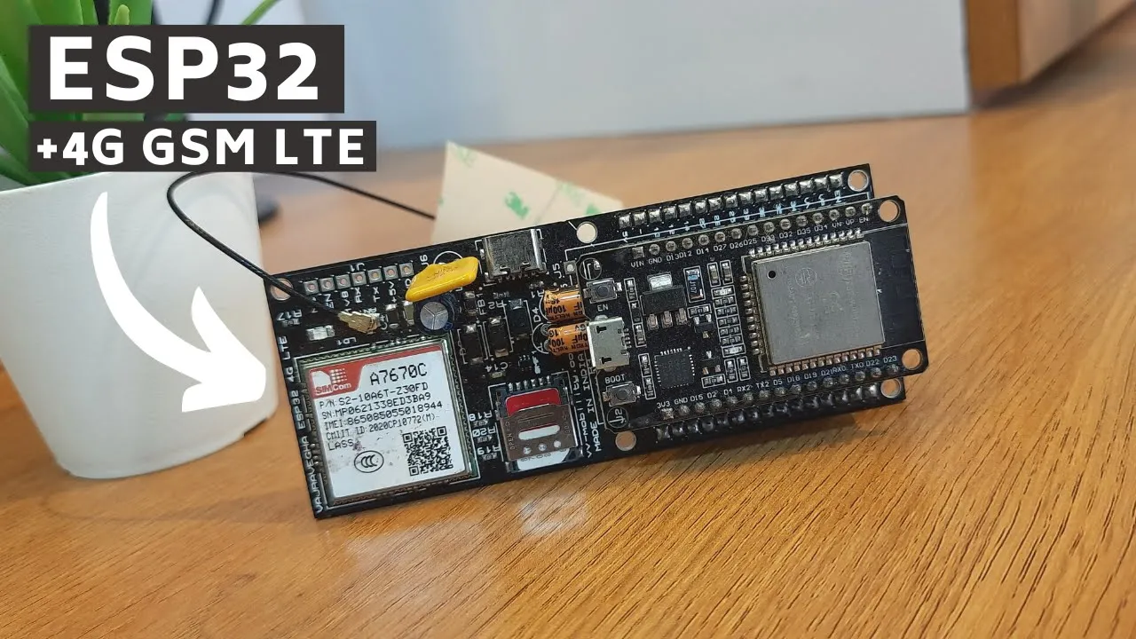
ESP32 4G GSM LTE - Now Send Data to Cloud without using WiFi!! (in Hindi)
42.7K
The VVM5001 ESP32 4G LTE module integrates an ESP32 microcontroller with a 4G GSM module, enabling IoT devices to send data to cloud platforms like Blink using cellular networks instead of WiFi. This affordable board (₹200-400) supports nano SIM cards and allows users to upload sensor data (such as temperature and humidity from DHT11 sensors) directly to the cloud using their SIM card's internet plan, making it ideal for IoT projects in areas without WiFi infrastructure.
Click to watch →
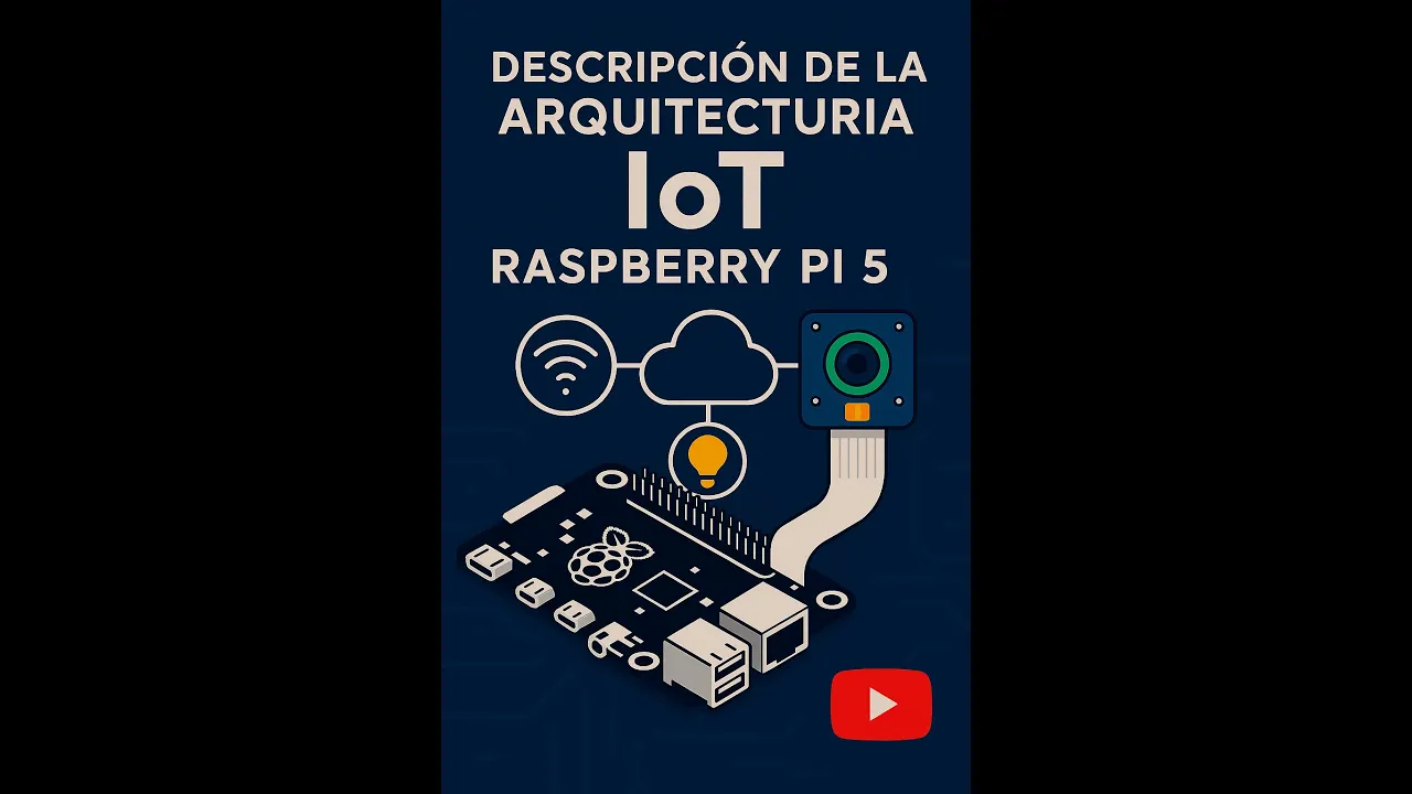
🔥 Arquitectura IoT con Raspberry Pi 5: Desde Sensores hasta la Nube – ¡Todo en 1 Video! 📊 #IoT
109
Communication protocols transfer data from intelligent devices to cloud platforms. WiFi provides direct IP-based communication, while Zigbee and LoRaWAN require gateway conversion to IP. LTE and NB-IoT provide direct IP communication without gateways. Cloud platforms receive data through protocols like Socket (fundamental IP communication), MQTT (standardized IoT protocol enabling third-party device connections), HTTP, and CoAP. MQTT's standardization advantage allows seamless multi-device integration. Cloud platforms store received data in databases (MySQL, SQL, Oracle, Progress) for processing and retrieval. The Cloud Application layer provides the user interface for monitoring and controlling IoT devices remotely, representing the end-user interaction point of the system.
Click to watch →

Monitoramento e controle de elevatória utilizando tecnologia 4G, protocolo MQTT
166
A telemetry monitoring system for wastewater pump stations uses 4G connectivity and MQTT protocol to enable remote real-time monitoring and control of pump operations, with data flowing from field devices through a broker to a supervisory system, allowing operators to monitor pump status, electrical parameters, and water levels while executing remote control commands.
Click to watch →
System Setup
Load Check
Delivery Done
System Setup
0:00- 1
Introduces AGV hardware including microcontroller, motors, and sensors.
- 2
Details power supply conversion from lead-acid battery.
Autonomous Mobile Robots (AMRs) with SLAM and ROS vs. Traditional Microcontroller-Based AGVs
While low-level, microcontroller-based AGVs utilizing RFID and ultrasonic sensors are cost-effective for basic educational setups, they are increasingly obsolete in modern industrial environments. Industry 4.0 heavily favors Autonomous Mobile Robots (AMRs) driven by powerful Single Board Computers (SBCs) running the Robot Operating System (ROS) and Simultaneous Localization and Mapping (SLAM). Unlike rigid, infrastructure-dependent RFID AGVs, SLAM-enabled AMRs dynamically map and navigate factories without physical markers, using LiDAR and computer vision instead of basic ultrasonic sensors. Furthermore, bare-metal Embedded C on 8-bit microcontrollers (like AVR) lacks the computational power, safety certifications (e.g., ISO 13849), and multi-threading capabilities required for complex industrial sensor fusion. For telemetry, legacy GSM is being phased out globally, replaced by high-bandwidth, low-latency technologies like Wi-Fi, 5G, or private LoRaWAN. Consequently, modern industrial automation prioritizes robust Programmable Logic Controllers (PLCs) and ROS-based AMRs over hobbyist-grade microcontroller architectures.
Fundamentals of Embedded C programming, including register-level configuration, interrupt service routines (ISRs), and memory management.
AVR microcontroller architecture (e.g., ATmega328P or ATmega16) and control of peripheral interfaces like GPIOs, Timers, and PWM.
Basic serial communication protocols, particularly UART (Universal Asynchronous Receiver-Transmitter) used by RFID and GSM modules.
Principles of sensor interfacing, specifically calculating distance using ultrasonic sensor trigger/echo pulses and reading RFID tag data.
Advanced autonomous navigation techniques, such as SLAM (Simultaneous Localization and Mapping) and the integration of LiDAR or computer vision.
Introduction to ROS (Robot Operating System) for high-level path planning, localization, and fleet coordination.
Industrial communication protocols (like CAN bus or Modbus) to integrate the AGV into a broader factory automation ecosystem (PLC/SCADA).
Transitioning from GSM to modern IoT protocols (such as MQTT over Wi-Fi/4G) to push load-monitoring telemetry to cloud platforms for real-time analytics.
38.8K views440likes5:43@Emtron_TechnologiesOriginal Release: 2016-08-30
welcome to bsp embed today I'm going to show you the project demo on automated guided vehicle here is the project it consist of art Mega 32A microcontroller 16x2 LCD and a two dpdt relays to switch a single art from a microcontroller into GSM Mam and two RFID readers an l293 motor driver to drive the DC gear motor and a Servo motor for the steering control of the vehicle and two RFID raders one at the bottom to detect the path and one to detect the goods a load cell which is used to measure the weight and a HX 71 a 24bit ADC to measure the load cell values an ultrasonic sensor to detect the object distance the entire system is powered from to's lead AED battery which is converted to 5 Vols using 7805 regulator and RFID tax for the path detection a heavy load a wrong goods and a right Goods let's over on once the power is applied to the microcontroller it will initializes the perference like GP timer and you want once this initialization is completed it will continuously measure the load on the vehicle if it is overload then it will be detected and continuously the buzzer will s so if you put a the light B then there is no indication then the vehicle will move [Music] the object is detected hence the vehicle got stopped after that it will send the message to the concerned person we re the message object detected automated SMS by automated get V the for card left right the destination [Applause] yeah the destination is reached and it will send the s destination reach automated SMS by AVG once the destination is reached we can unload the Goods so the black one is the right Goods if the wrong Goods is detected it will send the SMS so wrong Goods detected there is the message detected automated SS by AJ thank you for watching this video if you like please Thumbs Up And subscribe see you next time
Up Next
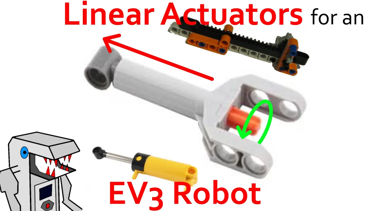
4:57
Linear Actuators Explained: 4 LEGO Technic Builds
@Builderdude35
145.5K views•2015-03-26

30:32
Ultrasonic Transducers: Resonant Frequency Measurement and Horn Design
@imajeenyus42
229.9K views•2017-02-22

54:16
Polymer Environmental Degradation: Mechanisms & Stabilization
@iit
1.8K views•2012-07-10

33:39
How a Student's Question Saved a NYC Skyscraper from Collapse
@veritasium
22.8M views•2025-04-26
Related Study Plans & Knowledge Roadmaps
Structured learning paths in Engineering
engineering
Building Acoustic Levitators: Physics & Arduino
01The Physics of Sound and Standing Waves
02Piezoelectric Transducers and H-Bridge Drivers
03Arduino Programming: Generating 40 kHz Signals
+ 2 more learning modules
14h5 modules
Explore Roadmap
engineering
Building Peltier Cloud Chambers: Particle Tracks
01Cosmic Rays & Cloud Chamber Physics
02Thermoelectric Cooling (TEC) Fundamentals
03Custom Liquid-Cooling Loop Design
+ 2 more learning modules
18h5 modules
Explore Roadmap
engineering
Yagi-Uda Antennas: Modeling, Build & VNA Test
01Introduction to RF and Antenna Fundamentals
02Yagi-Uda Antenna Design Principles
03Antenna Modeling and Simulation in 4NEC2
+ 2 more learning modules
18h5 modules
Explore Roadmap
engineering
ECG Monitor Design: Op-Amps, Filters & Noise
01Electronics & Breadboard Basics
02Op-Amps and Instrumentation Amplifiers
03Bioelectricity and ECG Fundamentals
+ 2 more learning modules
18h5 modules
Explore Roadmap