An Arduino XY Plotter Drawing Robot uses two stepper motors controlled by an Adafruit Motor Shield to move a pen across a surface, creating drawings based on coordinates generated by the Polargraph software; the system requires calculating steps per revolution (typically 400 for dual motors) and millimeters per revolution based on pulley and belt specifications, then uploading firmware to the Arduino UNO and running the Polargraph server application to generate and execute drawing commands.
Arduino XY Plotter Drawing Robot: Build & Program Tutorial
Added:Deep Dive
Basic familiarity with the Arduino ecosystem, including writing and uploading code via the Arduino IDE.

Arduino Programming Masterclass: From Basics to Libraries in 90 Mins
3.6M
The Arduino IDE enables writing and uploading code to boards. Available versions include Arduino IDE 1, Arduino IDE 2, and a web editor. Installation creates a sketchbook folder storing projects and libraries. The workflow involves: connecting via USB, selecting board type under Tools > Board, choosing COM port under Tools > Port, clicking Verify to compile and check errors, then clicking Upload. Every program requires void setup() (runs once for initialization) and void loop() (runs repeatedly forever). Variables store data using data types (boolean, byte, int, long, float, char), names, assignment operators (=), and initial values. Semicolons terminate statements. The Blink example demonstrates basic functionality by toggling the onboard LED.
Click to watch →
![Ардуино уроки программирование для начинающих с 9 лет [с нуля] #ДомаВместе](https://i.ytimg.com/vi/RwO_4nhRTUM/maxresdefault.jpg)
Ардуино уроки программирование для начинающих с 9 лет [с нуля] #ДомаВместе
114.8K
Arduino IDE is the software for writing and uploading code to Arduino boards. Download from the official website, choosing between classic installer (Windows XP+), portable version (no admin rights needed), or versions for Windows 8/10. The classic version is recommended. During installation, accept the free license agreement, select software, drivers, shortcuts, and file association for .ino files. Allocate 470-500 MB of free space. After installation, connect Arduino via USB to a computer port (prefer rear ports for better connection quality). The board's LED indicators confirm power status: 'ON' for Uno, green LED for Nano.
Click to watch →

Arduino Coding for Beginners | How to Program an Arduino?
591.5K
Arduino IDE (Integrated Development Environment) is a free software used for writing, compiling, and uploading code to Arduino boards. It functions as a lightweight text editor where you write your code. The code written inside Arduino IDE is called an Arduino sketch. Arduino programming uses a language similar to C++ and is designed to be very easy to learn. The code is first compiled into machine-readable language and then uploaded to the Arduino board.
Click to watch →
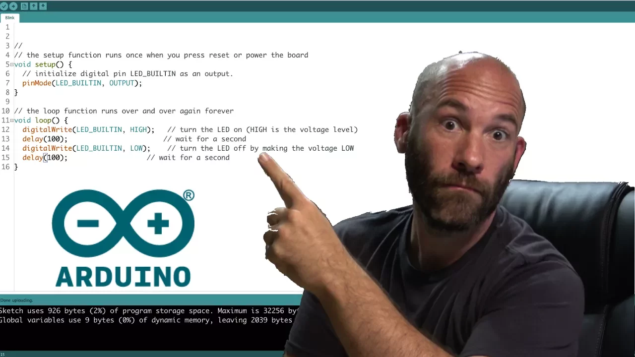
Arduino IDE Introduction
210.4K
The Arduino IDE is an integrated development environment used to write and upload code to Arduino boards, featuring essential tools like code verification, auto-formatting, serial monitoring, and serial plotting; key configurations include enabling line numbers and code folding in preferences, selecting the correct board type and COM port in the tools menu, and using the sketch menu to verify code, upload to the board, and include necessary libraries for advanced functionality.
Click to watch →

Basic concept of Arduino in Hindi | Arduino tutorials for beginners part #1
1.4M
Arduino IDE is free software available for all operating systems (Windows, Mac, Linux). Download from Arduino website by searching 'Arduino IDE' and clicking the first official option. After installation, the desktop icon launches the IDE containing: File menu (New, Open, Save), Examples menu with pre-written code templates (LED blinking, LCD interfacing, sensors), Sketch menu with Include Library for sensor commands, and Tools menu for board and port selection. For successful programming, select the correct board (Uno, Mega, Nano, Mini) and the connected serial port (e.g., COM3). The Upload button transfers programs to Arduino, enabling control of connected components like the built-in LED on pin 13.
Click to watch →
Deep Dive
Fundamental concepts of stepper motors and motor drivers (such as the A4988 or CNC Shield), particularly how electrical pulses translate to physical steps.
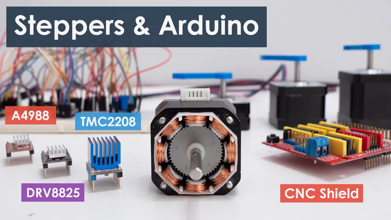
Controlling Stepper Motors with Arduino: A Guide
1.6M
This comprehensive section covers the foundational concepts of stepper motors and the A4988 driver system. Stepper motors are brushless DC motors capable of precise position control without feedback, consisting of a stator with coils and a permanent magnet rotor. The NEMA 17 is the most popular maker motor, featuring 200 steps per revolution (1.8°/step) or 400 steps (0.9°/step), with NEMA designations indicating faceplate size in tenths of inches. The A4988 driver provides current limiting via a trimmer potentiometer, with two methods for adjustment: measuring reference voltage (I = Vref/RCS) or using an ammeter in series with one coil. Motor phase identification is achieved by rotating the shaft - connecting wires from the same phase increases resistance. Microstepping increases resolution beyond basic steps, with the A4988 supporting up to 16-microstep mode (3200 steps/rev).
Click to watch →
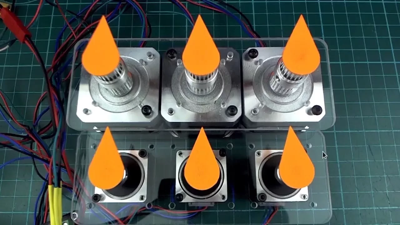
Arduino Coordinated Stepper Motor Control with Acceleration
367.7K
The A4988 stepper motor driver simplifies controlling stepper motors by requiring only two control pins per motor: direction and step. The direction pin determines rotation direction (high or low), while the step pin triggers individual steps when taken high. The enable pin can be held constant as it doesn't require intelligent signaling. This reduces the number of Arduino pins needed from four to two per motor, enabling control of multiple motors with fewer resources. The speed is inversely proportional to the interval between step pulses, meaning shorter delays between pulses result in faster motor movement.
Click to watch →
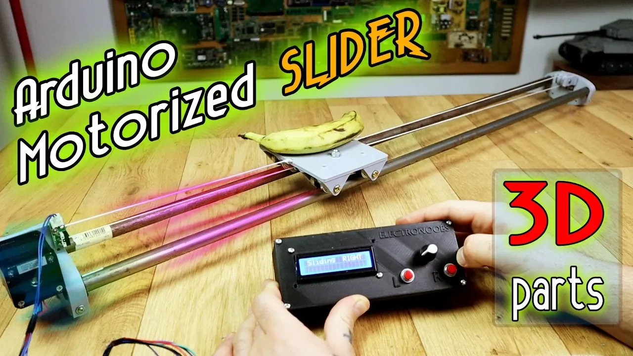
Step motor slider - Arduino and 3D printed body
138.5K
The A4988 driver controls a step motor using three primary signals: the enable pin (which activates the driver when set to low), the direction pin (which determines rotation direction—low for left, high for right), and the step pin (which receives square wave pulses). Each transition of the step pin from high to low or low to high causes the motor to advance by one step. This allows precise control over both the position and speed of the motor through software manipulation of these three signals.
Click to watch →
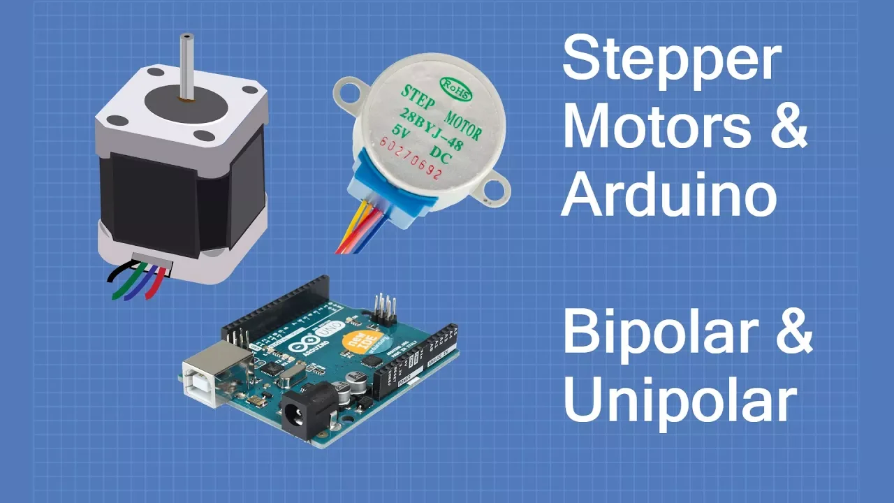
Stepper Motors with Arduino - Controlling Bipolar & Unipolar stepper motors
2.3M
The A4988 is a self-contained stepper driver handling up to 2A (with heatsink) for bipolar motors. Pinout includes: VMOT/GND for motor power (up to 30V), 1A/1B/2A/2B for coil connections, VDD/GND for logic (3-5.5V), ENABLE (active low), MS1/MS2/MS3 for microstepping modes (full, half, quarter, eighth, sixteenth steps), RESET/SLEEP (active low), STEP for pulses, and DIR for direction. Current limiting adjustment via onboard potentiometer must match motor specs (measure current during setup). Requires 47-100μF decoupling capacitor. Directly accepts step pulses and direction signals from Arduino, eliminating complex library requirements.
Click to watch →
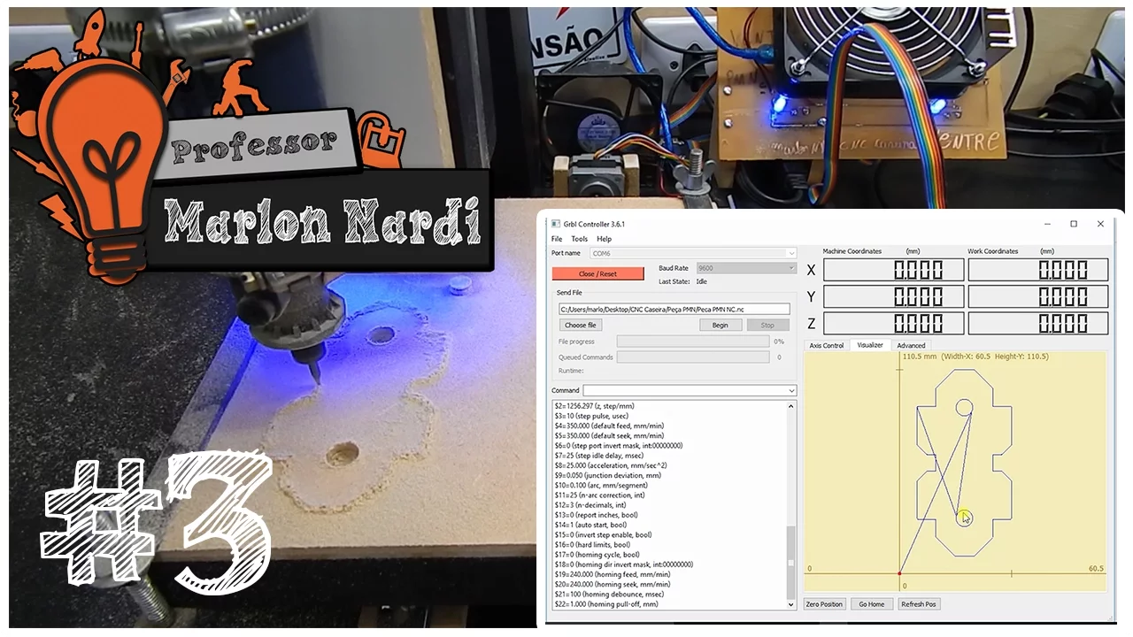
Construa sua CNC Própria CNC #3 | Eletrônica, Software, GRBL, G-code, Makercam e Usinando Peça
217.1K
Stepper motor drivers receive two digital signals from the Arduino: one pin sends pulses that determine the number of steps (each pulse causes a 0.1-0.5V variation), and the other pin controls direction. When the direction pin is active, the motor rotates in one direction; when inactive, it rotates in the opposite direction. The number of pulses directly corresponds to the motor's rotational position.
Click to watch →
Deep Dive
Understanding of the Cartesian coordinate system (X and Y axes) and how 2D space is represented numerically.

1st FREE MATHS Class by Ritik Sir | Class 9th Neev 2027 Batch 🔥
237.5K
This segment covers the Cartesian system, which uses two perpendicular reference lines to locate any point on a 2D plane: the horizontal x-axis and the vertical y-axis. Both are number lines with zero at their intersection point. Positive numbers extend right on the x-axis and upward on the y-axis, while negative numbers extend left and downward. The instructor defines the two coordinates: the x-coordinate (abscissa) represents the perpendicular distance from the y-axis, and the y-coordinate (ordinate) represents the perpendicular distance from the x-axis. He emphasizes that coordinates are always written in the order (x, y). The entire system is called the Cartesian plane or XY plane, which is divided into four quadrants: Quadrant I (top-right) has both x and y positive; Quadrant II (top-left) has x negative and y positive; Quadrant III (bottom-left) has both x and y negative; Quadrant IV (bottom-right) has x positive and y negative.
Click to watch →

Prashnawali 7.1 class 10th||Ncert class 10th math exercise 7.1  निर्देशांक ज्यामितिक, by pankaj sir
2.5M
The Cartesian coordinate system consists of two perpendicular axes: the x-axis (horizontal) and y-axis (vertical). The x-axis has positive values to the right and negative values to the left. The y-axis has positive values above the origin and negative values below. The origin (0,0) is the intersection point. The four quadrants are: First Quadrant (top-right, +x, +y), Second Quadrant (top-left, -x, +y), Third Quadrant (bottom-left, -x, -y), and Fourth Quadrant (bottom-right, +x, -y). To determine which quadrant a point belongs to, examine the signs of its coordinates. For example, (4,5) is in the First Quadrant, (-3,4) is in the Second Quadrant, and (-3,-7) is in the Third Quadrant.
Click to watch →
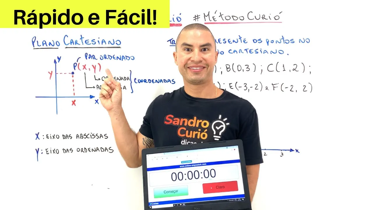
RÁPIDO e FÁCIL | PLANO CARTESIANO | PRODUTO CARTESIANO
871.3K
The Cartesian plane consists of two perpendicular axes: the x-axis (horizontal) and y-axis (vertical). The x-axis is also called the abscissa, while the y-axis is called the ordinate. Points on this plane are represented as ordered pairs (x, y), where x represents the horizontal distance from the origin and y represents the vertical distance. The order of coordinates is crucial - always list the x-coordinate first, followed by the y-coordinate.
Click to watch →
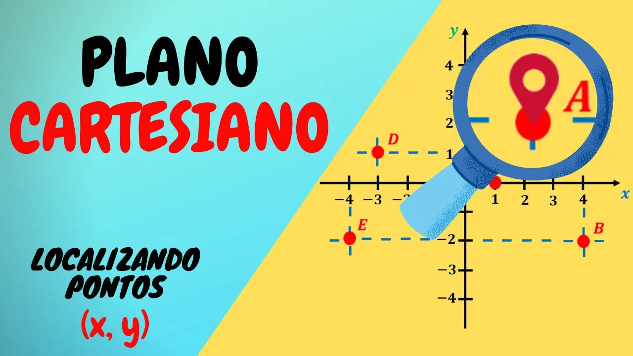
PLANO CARTESIANO – COMO LOCALIZAR PONTOS E ENTENDER EIXOS X E Y
15.8K
The Cartesian plane consists of two perpendicular axes: the horizontal x-axis (abscissas) and the vertical y-axis (ordinates), intersecting at the origin (0,0). The plane is divided into four quadrants: Quadrant I (positive x, positive y), Quadrant II (negative x, positive y), Quadrant III (negative x, negative y), and Quadrant IV (positive x, negative y). Coordinates are represented as ordered pairs (x, y), where the first number indicates horizontal movement from the origin and the second indicates vertical movement. To locate a point, start at the origin, move horizontally by the x-value, then vertically by the y-value. Conversely, to find coordinates of a point, read its horizontal position on the x-axis and vertical position on the y-axis.
Click to watch →

Nirdeshank Jyamiti Objective Question || Class 10th Math Chapter 7 Objective Question
86.1K
The Cartesian coordinate system consists of two perpendicular axes: the x-axis (horizontal) and y-axis (vertical) intersecting at the origin (0,0). The plane is divided into four quadrants: Quadrant I (+,+), Quadrant II (-,+), Quadrant III (-,-), and Quadrant IV (+,-). To determine which quadrant a point lies in, examine the signs of its coordinates. For example, (-2, +3) lies in Quadrant II because x is negative and y is positive.
Click to watch →
Deep Dive
Elementary practical electronics, including circuit safety, handling external power supplies, and breadboard prototyping.
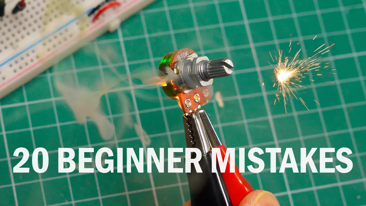
20 Things in Electronics That Confused me 20 Years Ago
26.6K
This section focuses on practical skills and safety considerations for electronics work. It addresses breadboard resistance effects that cause voltage drops, multimeter safety precautions (especially probe connections), and safe circuit building practices using breadboards instead of mid-air construction. The content covers RGB LED connection requirements (separate resistors per color), soldering technique fundamentals (cleaning, temperature, tip maintenance), and critical thinking about circuit sources found online. These practical insights help prevent component damage, improve measurement accuracy, and ensure reliable circuit operation.
Click to watch →

Complete beginner's guide to using a breadboard
206.7K
A breadboard is a reusable prototyping platform where electronic components are connected through interconnected metal strips; understanding its internal structure (power rails running along the sides and interconnected tie-point chains in the middle sections) enables proper circuit assembly, while component handling requires attention to polarity (especially for LEDs and capacitors) and proper power supply configuration for ICs.
Click to watch →

Testando Fonte Variavel Protoboard Curso de Eletronica basica #19
20.6K
This comprehensive section introduces practical electronics training and covers the fundamental components of a variable power supply circuit. The instructor explains the protoboard as a testing matrix for circuits before permanent soldering. Key components include: transformer (110/220V to 12V), fuse for protection, voltage selector switch, bridge rectifier for AC to DC conversion, LM317 voltage regulator, capacitor for filtering, potentiometer for voltage adjustment, and LED indicator with current-limiting resistor. The instructor emphasizes safety, including wearing an anti-static wrist strap to prevent component damage. The section covers circuit diagram analysis, proper protoboard component placement, and demonstrates how schematics guide circuit design and troubleshooting.
Click to watch →
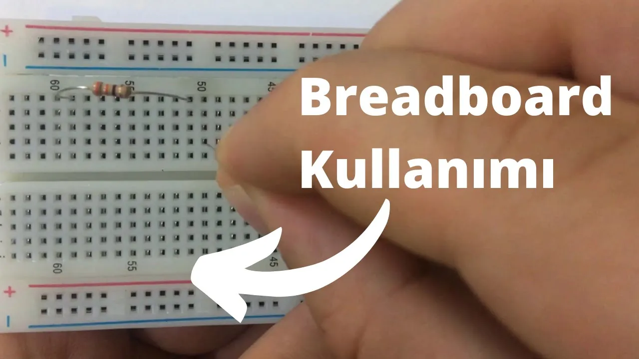
Breadboard Nasıl Kullanılır? , Breadboard Üzerine Elektronik Devre Kurulumu
98.8K
A breadboard is an electronic prototyping board with conductive pathways underneath its holes that connect specific groups of holes together, allowing users to build and test electronic circuits without soldering; the board features power rails (marked with + and -) that connect all holes in a single row, and the main circuit area where components can be connected in series (end-to-end) or parallel (all connected to the same power rails), with the total resistance in series circuits being the sum of individual resistances (R_total = R1 + R2 + R3) and in parallel circuits being calculated as 1/R_total = 1/R1 + 1/R2 + 1/R3.
Click to watch →

belajar hardware sama @ArtificialPortal & @andhikanug
66.8K
Breadboards are prototyping tools that allow electronic components to be connected without soldering. They feature rows and columns of connected holes where components can be inserted. The horizontal rows are connected, while vertical columns are also connected, creating a grid for circuit experimentation. Electrical circuits require a complete loop for current to flow from the power source through components and back. Ground (GND) serves as the reference point in circuits, similar to earth ground in household wiring. Batteries have positive and negative terminals, and components like LEDs also have polarity. Current flows from positive to negative, and circuits must be complete for current to flow.
Click to watch →
Prerequisite Knowledge
- Concept 01Basic familiarity with the Arduino ecosystem, including writing and uploading code via the Arduino IDE.
- Concept 02Fundamental concepts of stepper motors and motor drivers (such as the A4988 or CNC Shield), particularly how electrical pulses translate to physical steps.
- Concept 03Understanding of the Cartesian coordinate system (X and Y axes) and how 2D space is represented numerically.
- Concept 04Elementary practical electronics, including circuit safety, handling external power supplies, and breadboard prototyping.
Subsequent Learning
- Step 01Introduction to G-code generation and parsing, moving from proprietary software to industry-standard CNC instruction sets.
- Step 02Study of advanced robot kinematics, including the mathematical coordinate transformations required for polar (suspension) plotters or SCARA arm configurations.
- Step 03Integration of closed-loop feedback systems using rotary encoders to dynamically correct motor drift and physical slippage.
- Step 04Scaling plotter mechanics to construct more complex multi-axis digital fabrication tools, such as 3D printers, laser cutters, or desktop CNC mills.
Opening
Main Segment
Core Argument
Conclusion
Opening
2:06Playing Section
- 1
Starts with visual and musical setup.
- 2
Initial scenes establish core atmosphere.
Cartesian Gantry Systems vs. Suspended Polar (Polargraph) Designs
While Arduino-powered Polargraph (hanging V-plotter) systems are popular for their simplicity, low cost, and ability to scale to large surfaces, they suffer from significant performance limitations compared to Cartesian gantry-style plotters. Polargraphs rely on gravity and suspended belts, leading to issues like pen wobble, decreased precision near the edges of the canvas, slow drawing speeds, and susceptibility to environmental drafts. Conversely, Cartesian XY plotters utilize rigid rails and fixed gantries, offering vastly superior speed, repeatability, and consistent geometric accuracy across the entire drawing area. For students, understanding these physical and kinematic trade-offs is crucial, as the ease of building a suspended plotter comes at the cost of precision engineering standards.
Deep Dive
Introduction to G-code generation and parsing, moving from proprietary software to industry-standard CNC instruction sets.

G code
21K
G-Code is the standardized programming language for CNC (Computer Numerical Control) devices, developed by Electronic Industrial Alliance in the 1960s and standardized as ISO 6983-1. The code consists of preparatory commands (G-codes) that control machine movements and operations, and auxiliary commands (M-codes) that control machine functions like spindle rotation and coolant. Key G-codes include G00 for rapid positioning, G01 for linear interpolation, G02/G03 for circular interpolation, and G90/G91 for absolute/incremental coordinate systems. Parameters such as X, Y, Z coordinates, F (feed rate), S (spindle speed), and R (radius) define specific machine behaviors. G-Code programs are typically generated using CAD/CAM software like ARCAM, PowerMill, or Type 3, which allow simulation of the machining process before actual execution.
Click to watch →
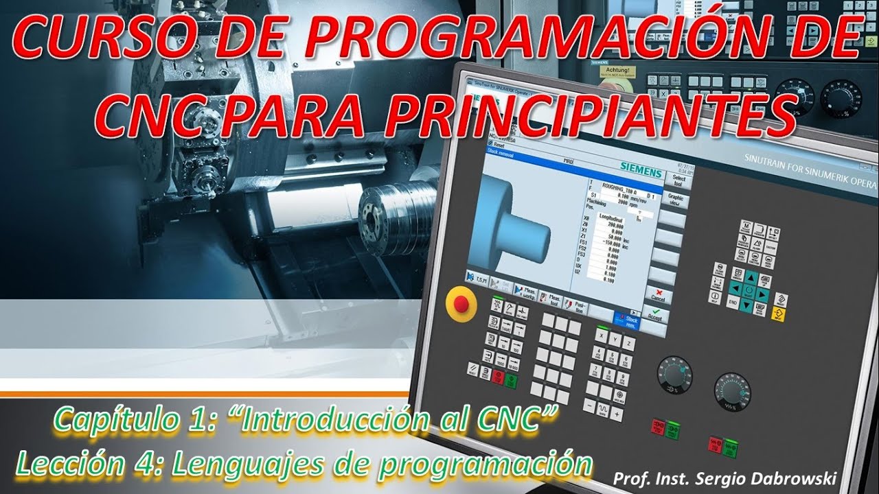
Curso de Programación de CNC para principiantes. Capítulo 1 Lección 4. Lenguajes de programación CNC
30.4K
CNC programming languages include ISO G-Code (the most widely used worldwide), conversational programming mode (for intuitive operation), and Step NC (developed by Siemens, Fanuc, and universities in 1999). ISO G-Code uses letter-based instructions: G-codes (G00-G99) for axis movements, M-codes (M00-M99) for auxiliary functions, and other letters (T, F, S) for tools, feed rates, and speeds. Functions are categorized into groups (0-15) including modal functions (active until cancelled) and non-modal functions (affect only the current instruction). CNC programs consist of numbered blocks containing words (uppercase letters with numeric values), separated by spaces, with end-of-block characters indicating instruction completion.
Click to watch →
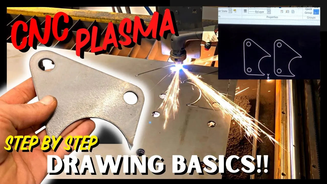
Beginner Introduction to AutoCAD 2D Drawing & Cutting CNC Plasma Parts
235.6K
G-code is the programming language that tells CNC machines where to move and what operations to perform. LazyCAM converts DXF files into G-code tap files that CNC controllers like Mach3 can execute. The CNC controller interprets the G-code instructions to control the machine's axes and plasma torch. Different CNC controllers may have different interfaces but follow the same fundamental principles.
Click to watch →
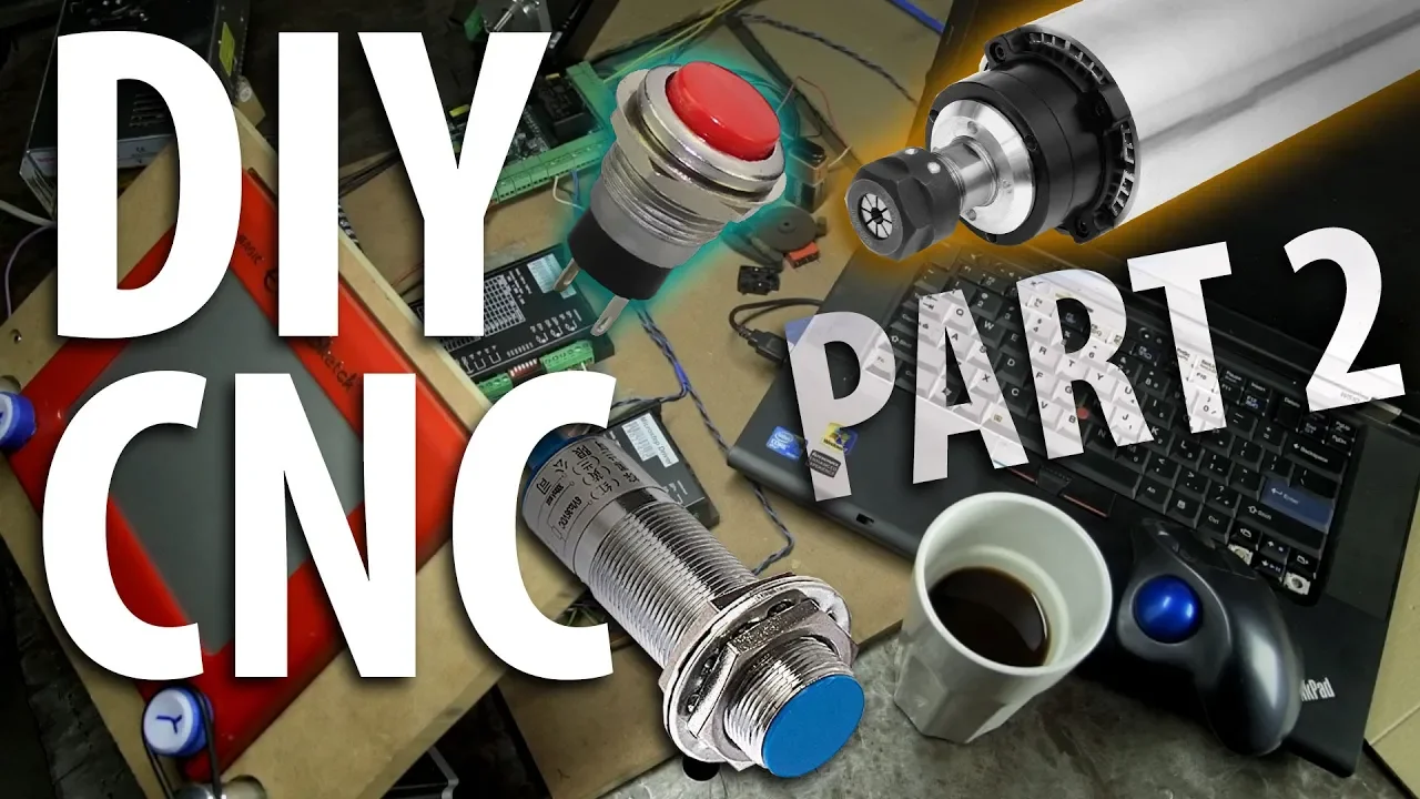
Build Your Own CNC! (Part 2) - Inputs, Outputs & Software
845K
CNC programs can be created through multiple methods: writing G-code manually in MDI or text editors, using CAM (Computer-Aided Manufacturing) software like Fusion 360 or HSM to generate sophisticated code from CAD models, or using built-in wizards/plugins for common operations like pockets, slots, and bolt hole patterns. CAM software generates more complex and optimized code than manual entry, making it the preferred method for professional CNC work.
Click to watch →
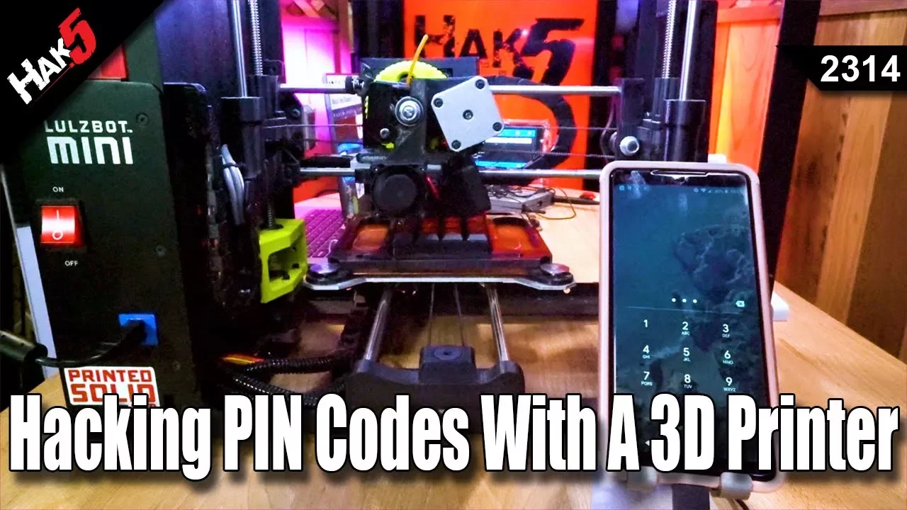
Hacking PIN Codes with a 3D Printer - Hak5 2314
22.1K
G-code is the universal programming language for all CNC machines including 3D printers, from budget devices to industrial robots. Commands start with 'G' for geometric functions and 'M' for machine-specific macros. Absolute mode (G90) specifies exact coordinates from the origin, while relative mode (G91) uses offsets from current position. Home position (G28) establishes the origin. Units are typically millimeters (G21). This standardized format enables interoperability across manufacturers and allows humans to directly read and modify machine instructions.
Click to watch →
Deep Dive
Study of advanced robot kinematics, including the mathematical coordinate transformations required for polar (suspension) plotters or SCARA arm configurations.
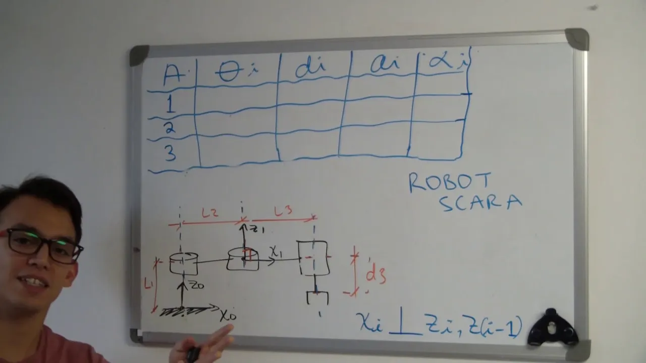
INTRO A CINEMÁTICA DE MANIPULADORES Y ROBOT SCARA
9.3K
This video demonstrates how to determine the Denavit-Hartenberg (DH) parameters for a SCARA robot manipulator, which consists of three rotational joints and one translational joint. The DH parameters include: theta (rotation angle about the z-axis to align x-axes), d (distance along the z-axis between origins), a (distance along the x-axis between origins), and alpha (rotation angle about the x-axis to align z-axes). For the SCARA robot shown, the parameters are calculated as follows: theta₁ = 30°, d₁ = l₁, a₁ = l₂, alpha₁ = 0°; theta₂ = 0°, d₂ = 0, a₂ = l₃, alpha₂ = 180°; theta₃ = 0°, d₃ = 0, a₃ = 0, alpha₃ = 0. The final DH matrix is constructed by substituting these values into the general DH matrix formula and multiplying the individual transformation matrices in sequence to obtain the global transformation from the base frame to the end effector.
Click to watch →
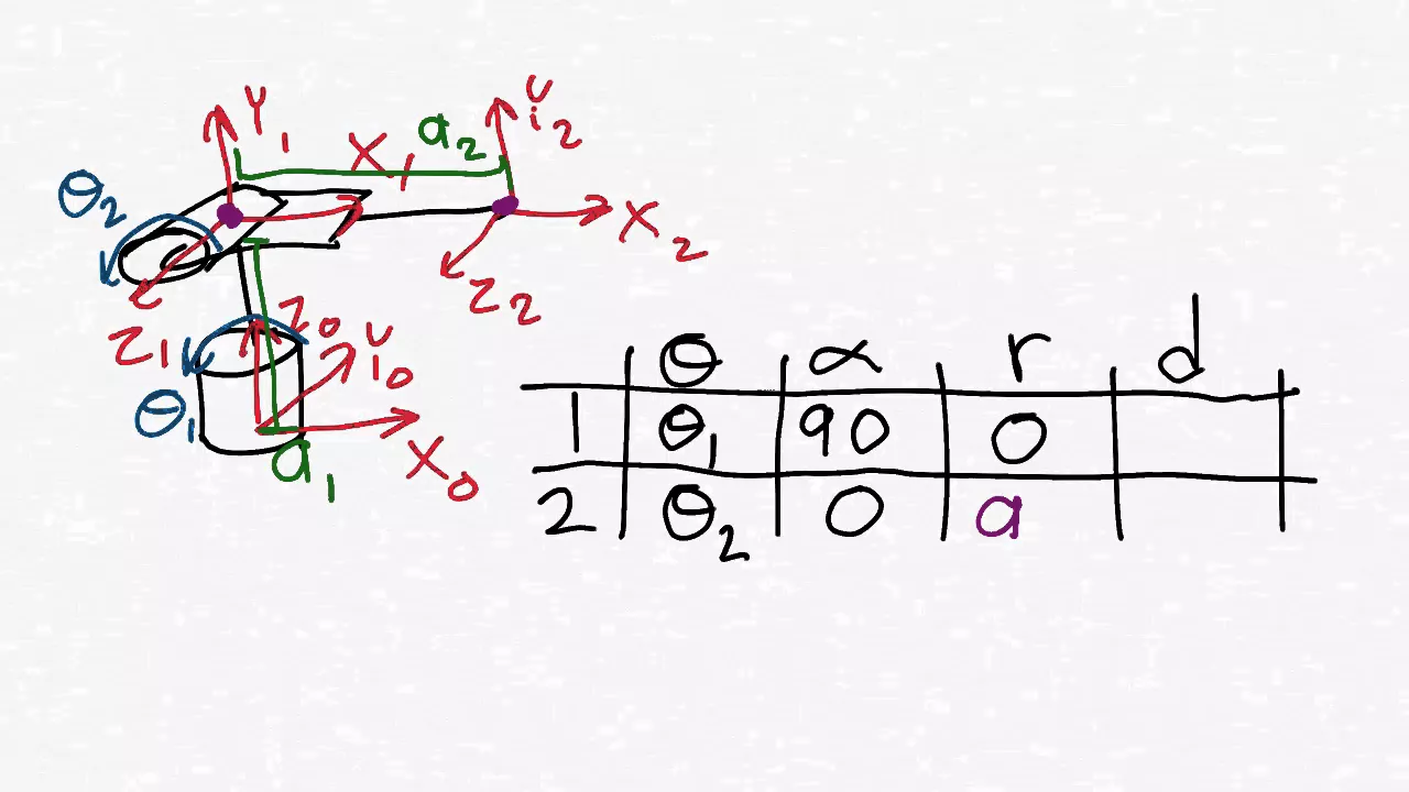
Robotics 1 U1 (Kinematics) S5 (HTM) P2 (HTM by Denavit Hartenberg)
297.6K
The Denavit-Hartenberg method provides an industry-standard shortcut for computing homogeneous transformation matrices in robotics. Unlike the direct method of separately finding rotation matrices and displacement vectors, this approach obscures the underlying meaning but offers computational efficiency. The method requires three essential steps: (1) drawing the kinematic diagram with frames assigned according to D-H rules, (2) creating a parameter table with four columns (theta, alpha, R, D) and rows equal to frames minus one, and (3) using this table to compute transformation matrices. The four parameters—theta (rotation around z(n-1) to align x-axes), alpha (rotation around x(n) to align z-axes), R (distance between centers along x(n)), and D (distance between centers along z(n-1))—systematically capture both rotational and translational relationships between consecutive frames.
Click to watch →

Spinning Build Platform? The Sculpto PRO2 Polar 3D Printer
105.8K
Polar 3D printers use a rotating build platform instead of stationary axes, employing r (radius), theta (angle), and z (height) coordinates rather than traditional Cartesian x, y, z. The Sculpto 2 Pro exemplifies this design, where the r value controls distance from the center point and theta describes angular position. This system holds all motion components within a fixed envelope, preventing size changes during printing. The printer features an authentic E3D hot end with holographic authenticity verification and a removable flexible build plate for easy part release without scrapers.
Click to watch →

Denavit - Hartenberg (DH) Tables For Robotic Systems - Direct Kinematics II
231.9K
The Denavit-Hartenberg (DH) representation is a systematic method for describing the position and orientation of robotic joints using four parameters: a_i-1 (link length, distance between joint axes along the common perpendicular), alpha_i-1 (link twist, angle between joint axes about the common perpendicular), d_i (link offset, distance between origins along the previous joint axis), and theta_i (joint angle, rotation about the current joint axis). For prismatic joints, d_i is non-zero while theta_i is zero; for revolute joints, theta_i is non-zero while d_i is zero. These four parameters are organized into a DH table, which enables the calculation of transformation matrices that describe the spatial relationship between consecutive frames in a robotic manipulator.
Click to watch →
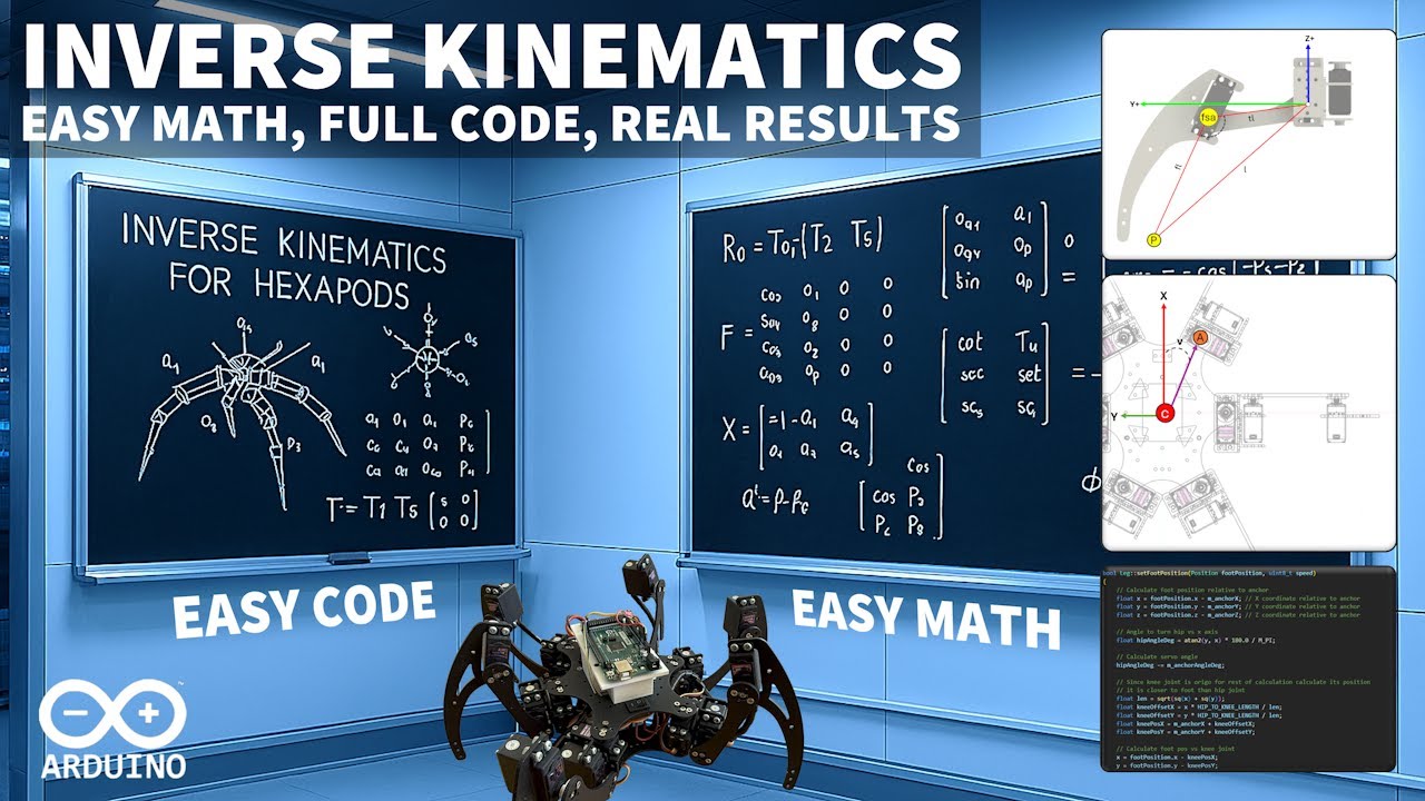
Master Inverse Kinematics for Arduino Robots – Easy Math, Full Code, Real Results
105.5K
Robot kinematics studies how robots move using joints (rotating parts like hips, knees, feet) and links (rigid connecting parts like thighs and feet). Forward kinematics tells each servo where to move, resulting in predictable foot positions but becoming impractical for complex movements. Inverse kinematics reverses this: specify desired foot position, then calculate required joint angles. A right-handed coordinate system is standard for robotics, with x-axis forward, z-axis up, and y-axis left when viewed from behind. Angles can be calculated in radians (Arduino default, full rotation = 2π) or converted to degrees for easier visualization. Three mathematical operations suffice for inverse kinematics: calculating angles from single lines using arctan, solving right triangles with known sides, and calculating any triangle's angles when all three sides are known.
Click to watch →
Deep Dive
Integration of closed-loop feedback systems using rotary encoders to dynamically correct motor drift and physical slippage.

Applied Motion Products Presents Encoder Feedback
85.4K
Adding an encoder to a stepper motor system enables closed-loop control, providing two key benefits: stall detection (which immediately notifies the user when a motor stall occurs) and stall prevention (which dynamically adjusts motor current and speed to maintain torque and prevent stalling), thereby eliminating the uncertainty of whether the motor reached its target position and enabling advanced control schemes like torque-limited velocity and position control.
Click to watch →

Why the brushless controllers are awesome for robotics
145.2K
Closed-loop position control compares actual rotor position (from encoder) against a setpoint to compute error. Maximum torque requires 90-degree phase advance relative to rotor position, implemented as +12 or -12 steps in the 48-value array. SPI-based encoder reading eliminates PWM noise, providing stable position tracking. The control algorithm maps encoder values to electronic shaft positions, applies proportional torque based on error magnitude, and includes experimental offset compensation for mechanical misalignment. This enables precise motor positioning with minimal vibration.
Click to watch →
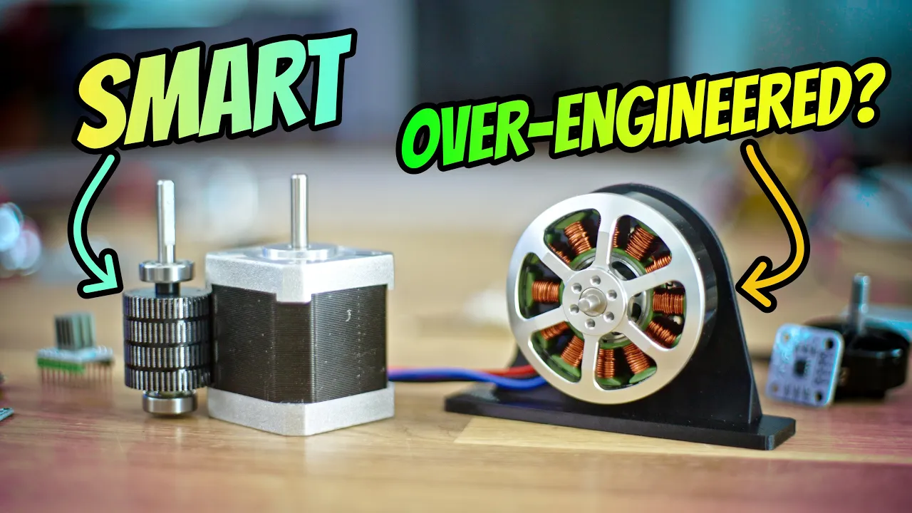
Steppers vs Servos in 3D Printers: An Engineering Analysis
280.8K
Positional feedback transforms any motor into a servo through encoders—magnetic or optical devices measuring rotational position. Magnetic encoders attach a magnet to the shaft and use chips to measure position, while optical encoders use graded transparent films or rotating sensors. Closed-loop systems detect external disturbances and compensate, unlike open-loop systems that lose steps silently. FOC requires precise rotor position knowledge to optimally control each coil, stopping current entirely when at target position. This contrasts with constant stepper energization, enabling dynamic current adjustment based on actual torque needs rather than fixed patterns.
Click to watch →

Watch Me Build Closed-Loop CNC Electronics in 25 Minutes
142.5K
This comprehensive segment explains the implementation of closed-loop motor systems with encoder feedback and demonstrates complete CNC system operation. Closed-loop stepper motors incorporate encoders on their shafts that provide feedback confirming actual rotation matches commanded output, ensuring precise positioning. The system uses three closed-loop drivers powered by 60-volt supplies and one open-loop driver powered by 48 volts for the Z-axis. Encoder cables require shielding and should be separated from motor cables to prevent electromagnetic interference. The video demonstrates soldering encoder connectors to panel-mounted receptacles using the wire combing technique for organized cable routing. Each encoder connector requires careful alignment with matching notches and secure fastening to prevent disconnection during operation. The final assembly includes preparing and soldering 50 feet of motor cable and encoder cable with heat shrink tubing protecting soldered sections. Dip switches on each driver control microstepping and current settings, requiring adjustment based on specific motor requirements. Voltage testing verifies power supply outputs before powering on the complete system. The demonstration shows jogging axes using keyboard arrow keys with audible motor operation confirming successful movement. Output signals are configured through Mach3 Ports and Pins settings, assigning outputs to specific ports and pins with active-low configuration. One relay controls both spindle directions while another controls both flood and mist functions simultaneously. Input capabilities include limit switches, home switches, and e-stops connected through dedicated input connectors. Ground connectors are essential for completing all electrical circuits. Analog voltage inputs (0-10V) enable PWM-controlled spindle speed adjustment.
Click to watch →
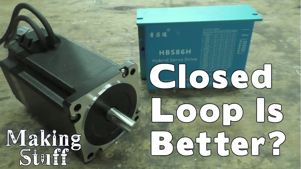
Closed Loop Stepper Motors for CNC machines
198.8K
A closed-loop stepper motor includes an encoder mounted on the back of the motor, connected via an extra cable. This encoder enables bidirectional communication between the motor and controller, allowing the motor to report its position and status. When the motor cannot move as commanded or misses steps, it can signal the controller about the problem.
Click to watch →
Deep Dive
Scaling plotter mechanics to construct more complex multi-axis digital fabrication tools, such as 3D printers, laser cutters, or desktop CNC mills.
PMG3 Mech Tutorial Part 1 - Build a Boat for Treasure
487.3K
Advanced builds require scaling blocks in multiple axes simultaneously. A block can be scaled inward, then downward, then outward in a sequence. This multi-axis scaling creates complex shapes from simple rectangular blocks and is essential for creating detailed mechanical components.
Click to watch →
![PK8 Rahmenaufbau Teil 03 / 2018 Anet A8 3D Drucker / Umbau auf PK8 / Upgrade to PK8 / [Ger] Full HD](https://i.ytimg.com/vi/pwpBhyFFOuI/hqdefault.jpg)
PK8 Rahmenaufbau Teil 03 / 2018 Anet A8 3D Drucker / Umbau auf PK8 / Upgrade to PK8 / [Ger] Full HD
1.4K
This segment explores the critical relationship between scaling and mechanical system functionality. The presenter explains that scaling 3D printer designs requires careful consideration of all axes simultaneously, as scaling the Z-axis differently from X and Y can cause component misalignment. The distance between angled components may become too large or too small, and glide axes may become too short, preventing proper compensation. The segment demonstrates how original parts must be scaled proportionally to maintain functional geometry, and how improper scaling creates mechanical problems that cannot be easily corrected.
Click to watch →
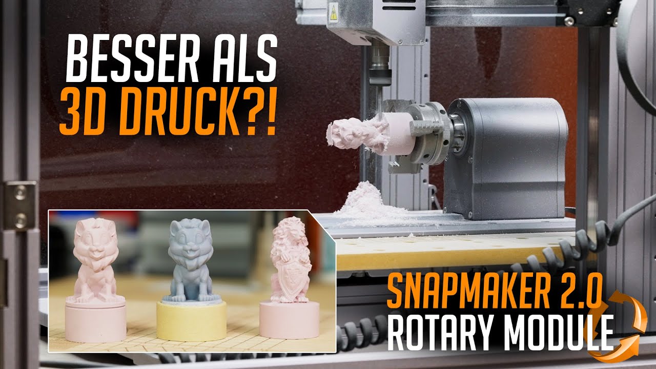
Snapmaker 2.0 - ROTARY MODULE | 360° LASER & CNC (Test 2021)
321.8K
Modular manufacturing equipment allows manufacturers to extend functionality through interchangeable modules without redesigning the entire product. The Snapmaker 2.0 demonstrates this by offering a base unit that transforms into different machines (3D printer, laser engraver, CNC mill) through module additions. The rotation module extends laser and CNC functions by adding a fourth axis, enabling complete figure creation through circular laser cutting or multi-axis milling. CNC milling requires systematic setup including freeing the CNC plate, mounting with four screws, connecting via combo plug, and performing coordinate calibration (X1, X2, Y, Z, B-axis). The B-axis defines rotation reference points for materials with seams. The machine uses standard vice clamps for material securing. Software provides step-by-step guidance, and automatic WiFi updates ensure the machine remains current. This systematic approach ensures accurate and safe operation while providing users with flexibility and manufacturer adaptability.
Click to watch →
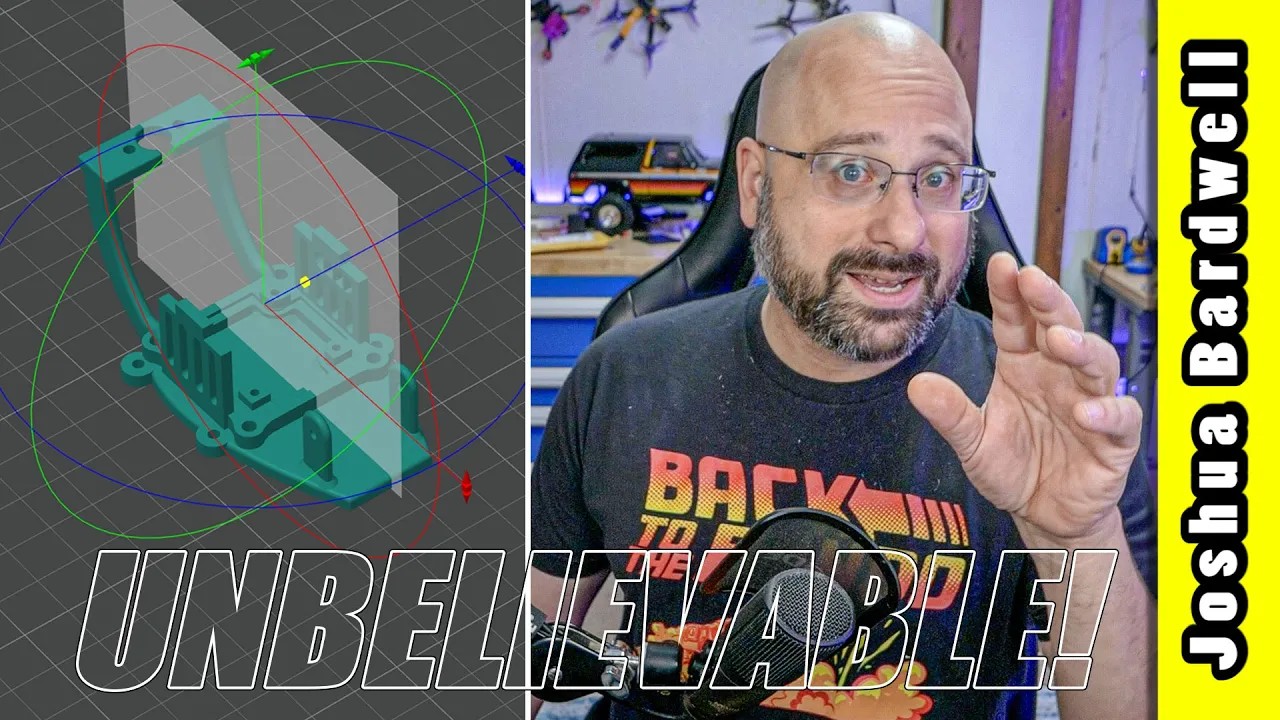
These tools let ANYONE remix 3D prints (no CAD skill required)!
76K
After adding a primitive shape, users can scale it to approximate size using the scale tool, then position it precisely using the move tool. Multiple primitives can be added and positioned to create completely original designs by combining and modifying existing parts.
Click to watch →
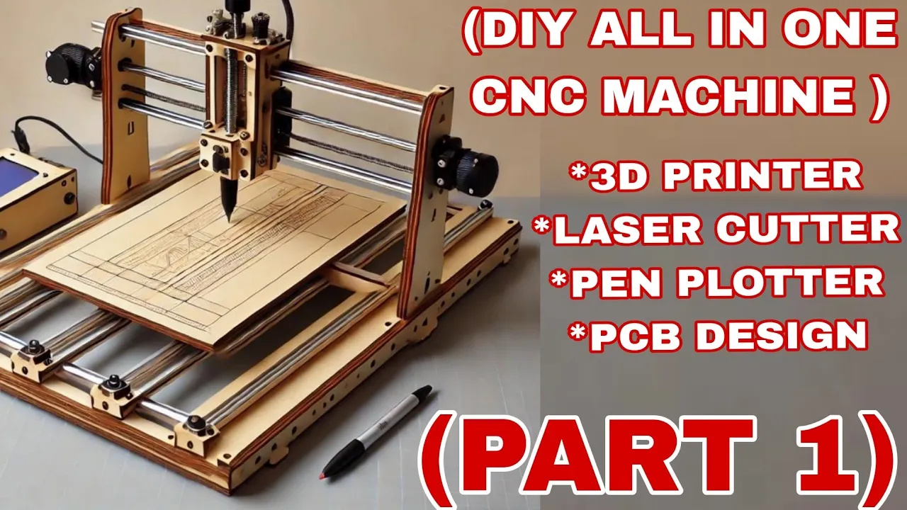
Make A Universal CNC Machine At home :- DIY 3D printer/Laser cutting/PCN milling All In One Machine
2.9K
A universal CNC machine frame can be constructed using MDF board, 8mm linear rods, stepper motors, linear bearings, lead screws, and couplers, creating a versatile platform that can be adapted into various machines such as a laser cutter, 3D printer, PCB milling machine, or pen plotter by modifying the tool and software components.
Click to watch →
Opening
Main Segment
Core Argument
Conclusion
Opening
2:06- 1
Starts with visual and musical setup.
- 2
Initial scenes establish core atmosphere.
Cartesian Gantry Systems vs. Suspended Polar (Polargraph) Designs
While Arduino-powered Polargraph (hanging V-plotter) systems are popular for their simplicity, low cost, and ability to scale to large surfaces, they suffer from significant performance limitations compared to Cartesian gantry-style plotters. Polargraphs rely on gravity and suspended belts, leading to issues like pen wobble, decreased precision near the edges of the canvas, slow drawing speeds, and susceptibility to environmental drafts. Conversely, Cartesian XY plotters utilize rigid rails and fixed gantries, offering vastly superior speed, repeatability, and consistent geometric accuracy across the entire drawing area. For students, understanding these physical and kinematic trade-offs is crucial, as the ease of building a suspended plotter comes at the cost of precision engineering standards.
Basic familiarity with the Arduino ecosystem, including writing and uploading code via the Arduino IDE.
Fundamental concepts of stepper motors and motor drivers (such as the A4988 or CNC Shield), particularly how electrical pulses translate to physical steps.
Understanding of the Cartesian coordinate system (X and Y axes) and how 2D space is represented numerically.
Elementary practical electronics, including circuit safety, handling external power supplies, and breadboard prototyping.
Introduction to G-code generation and parsing, moving from proprietary software to industry-standard CNC instruction sets.
Study of advanced robot kinematics, including the mathematical coordinate transformations required for polar (suspension) plotters or SCARA arm configurations.
Integration of closed-loop feedback systems using rotary encoders to dynamically correct motor drift and physical slippage.
Scaling plotter mechanics to construct more complex multi-axis digital fabrication tools, such as 3D printers, laser cutters, or desktop CNC mills.
592.2K views8.9Klikes10:14@maker101ioOriginal Release: 2017-11-12
[Music] so [Music] so [Music] so [Music] [Applause] so [Music] so [Music] [Applause] [Music] so [Applause] [Music] [Applause] so [Music] foreign [Music] foreign [Music] so [Music] do [Music] so [Music] so [Music] so [Music] so [Music] do [Music] so [Music]
Up Next

19:54
D'Alembert's Principle | Dynamics | Engineering Mechanics Tutorial
@ManasPatnaikofficial
269.3K views•2017-12-14

30:32
Ultrasonic Transducers: Resonant Frequency Measurement and Horn Design
@imajeenyus42
229.9K views•2017-02-22

54:16
Polymer Environmental Degradation: Mechanisms & Stabilization
@iit
1.8K views•2012-07-10

33:39
How a Student's Question Saved a NYC Skyscraper from Collapse
@veritasium
22.8M views•2025-04-26
Related Study Plans & Knowledge Roadmaps
Structured learning paths in Engineering
engineering
Building Acoustic Levitators: Physics & Arduino
01The Physics of Sound and Standing Waves
02Piezoelectric Transducers and H-Bridge Drivers
03Arduino Programming: Generating 40 kHz Signals
+ 2 more learning modules
14h5 modules
Explore Roadmap
engineering
Building Peltier Cloud Chambers: Particle Tracks
01Cosmic Rays & Cloud Chamber Physics
02Thermoelectric Cooling (TEC) Fundamentals
03Custom Liquid-Cooling Loop Design
+ 2 more learning modules
18h5 modules
Explore Roadmap
engineering
Yagi-Uda Antennas: Modeling, Build & VNA Test
01Introduction to RF and Antenna Fundamentals
02Yagi-Uda Antenna Design Principles
03Antenna Modeling and Simulation in 4NEC2
+ 2 more learning modules
18h5 modules
Explore Roadmap
engineering
ECG Monitor Design: Op-Amps, Filters & Noise
01Electronics & Breadboard Basics
02Op-Amps and Instrumentation Amplifiers
03Bioelectricity and ECG Fundamentals
+ 2 more learning modules
18h5 modules
Explore Roadmap