This video demonstrates how to control a Nema17 stepper motor using an A4988 driver module connected to an Arduino microcontroller, showing the wiring configuration and providing sample code for basic motor operation.
A4988 Stepper Motor Driver with Nema17 and Arduino Control
Added:Deep Dive
Basic Arduino programming, including familiarity with IDE setup, GPIO control, and basic functions like digitalWrite() and delay().
![#2 Instrucciones Básica [ pinMode, digitalWrite, delay ] - Curso Arduino 💻](https://i.ytimg.com/vi/dwet3or5rmQ/maxresdefault.jpg)
#2 Instrucciones Básica [ pinMode, digitalWrite, delay ] - Curso Arduino 💻
95.2K
This lesson teaches the fundamental Arduino programming concepts including pinMode() to configure pins as INPUT or OUTPUT, digitalWrite() to set pin states as HIGH (5V) or LOW (0V), and delay() to create time delays in milliseconds. The video demonstrates how to build a digital timer circuit using two LEDs (red on pin 10 to indicate timer start, green on pin 6 to indicate completion), explaining that Arduino executes code sequentially line-by-line, making delay functions essential for creating visible timing effects. The setup() function runs once at startup for configuration, while loop() runs continuously for ongoing operations.
Click to watch →

Arduino Начало!!! Установка Драйвера на Китайскую Ардуино и Урок 1
35.5K
This segment teaches the three fundamental Arduino programming functions. The pinMode() function configures pins as INPUT or OUTPUT, digitalWrite() sets pin states to HIGH or LOW, and delay() pauses execution for specified milliseconds. The presenter demonstrates a complete LED blinking program using these functions, explaining the setup() and loop() structure. The segment emphasizes that understanding these basic functions is essential for all Arduino programming, and that beginners should memorize these commands as building blocks for more complex projects.
Click to watch →
💡 Cómo usar un PROTOBOARD Arduino desde CERO【 2021 】 - Capítulo #03🔋
352K
Arduino programs use setup() for initial configuration and loop() for continuous execution. pinMode(pin, OUTPUT) configures pins for output. digitalWrite(pin, HIGH/LOW) controls pin states. delay(milliseconds) creates timing intervals. Together, these functions enable basic LED control. Programming requires proper syntax including semicolons to terminate statements. These fundamentals form the basis for all Arduino projects.
Click to watch →

Arduino | Basics | Part 1
112
Arduino programs use three core functions: (1) pinMode(pin, mode) configures pins as input or output, with 'OUTPUT' capitalized for devices like LEDs; (2) digitalWrite(pin, state) controls electrical state, where 'HIGH' supplies 5V and 'LOW' stops power; (3) delay(milliseconds) pauses execution for specified time. Case sensitivity is critical - 'OUTPUT', 'HIGH', and 'LOW' must be capitalized. These functions work together to control hardware components like LEDs.
Click to watch →

arduino starter kit e basi della programmazione
48.5K
Arduino programming uses the Arduino IDE (free from arduino.cc). Key concepts include: (1) Pin configuration using 'int led = 12' to assign pins to variables; (2) Setup function 'void setup()' runs once at startup; (3) Pin mode configuration with 'pinMode(led, OUTPUT)' to set pins as outputs; (4) Loop function 'void loop()' runs continuously; (5) 'digitalWrite(led, HIGH/LOW)' controls digital pins; (6) 'delay(milliseconds)' creates timing delays. A complete LED blinking program requires configuring pins, turning LED on, delaying, turning off, and delaying again within the loop.
Click to watch →
Deep Dive
Fundamental concepts of DC electronics, particularly voltage, current, breadboard wiring, and the importance of a common ground.
Intro to DC Electronics - Learn the Basics
1.1K
This introductory DC electronics class covers the basics of electricity through fluid analogies (water flow representing electron flow, pressure representing voltage), teaches how to read electrical schematics and build circuits using breadboards, explains voltage as electric potential difference (measured in volts), current as the flow of electrical charge (measured in amperes), and resistance (measured in ohms), demonstrates using a multimeter to measure these quantities, and introduces Ohm's Law (V=IR) and Kirchhoff's Laws for analyzing and designing simple DC circuits.
Click to watch →
01 - Grandezze elettriche: Tensione, Corrente e Terra (o GND o Ground o Massa)
8K
Voltage (measured in volts) is the energy that drives electrical charges through a circuit, analogous to a mechanism moving penguins up a ramp; current (measured in amperes) represents the quantity of charges passing through a circuit section over time, with conventional current flowing from positive to negative despite electrons actually moving in the opposite direction; ground (GND or Mass) provides a 0V reference point for measuring voltages, where the negative terminal of a generator is typically connected to establish this baseline.
Click to watch →
TutoDuino 3 : Notions de base en électricité
56.7K
A breadboard is a plastic prototyping board with organized holes for circuit testing. Holes are arranged in horizontal lines (1-30) where all points share the same electrical potential, while power rails (+ and -) connect vertically. Three core electrical concepts are essential: Voltage (U) is the potential difference measured in Volts, Current (I) is the electron flow measured in Amperes, and Resistance (R) opposes current flow measured in Ohms. Ohm's Law (R = U/I) governs circuit behavior. Arduino digital pins output 5V (HIGH) or 0V (LOW). LEDs require approximately 3V and 5mA to operate safely. Without a resistor, the 5V supply would cause excessive current, potentially burning the LED. The resistor value is calculated as R = (5V - 3V) / 0.005A = 400 Ohms.
Click to watch →
Tuto Live Arduino épisode 1 : Présentation et premiers pas
131.1K
Embedded systems combine electronics and computing for dedicated functions in devices like coffee machines and refrigerators. Electrical systems differ: household AC (230V, 50Hz) alternates polarity, while electronics use DC (constant voltage). Voltage represents electrical pressure driving electrons, while current measures electron flow rate. Breadboards enable solder-free prototyping with normalized hole spacing. Multimeters measure voltage (parallel connection) and current (series connection). Voltage remains constant across wires, while current flows through all series components. These fundamentals enable hands-on circuit experimentation and verification.
Click to watch →
![[EET1015C - Fundamentals of DC Circuits] Voltage, Current, Resistance, and Ohm's Law](https://i.ytimg.com/vi/imtCERdaFO0/maxresdefault.jpg)
[EET1015C - Fundamentals of DC Circuits] Voltage, Current, Resistance, and Ohm's Law
932
Ground is a reference point in all electric circuits from which all voltages are measured and serves as the common return path for electric current. Current exits the voltage source and must return to this ground point to complete the closed path. The term 'ground' originated from early electricity studies when one conductor was literally connected to an 8-foot metal rod driven into the earth. In circuit diagrams, multiple ground symbols represent the same single point of return. Every circuit must have a ground reference point and a common return path for current to flow properly.
Click to watch →
Deep Dive
The operational theory of stepper motors, including how bipolar stepper motors differ from standard DC or servo motors in terms of coils and phases.
Stepper Motors with Arduino - Controlling Bipolar & Unipolar stepper motors
2.3M
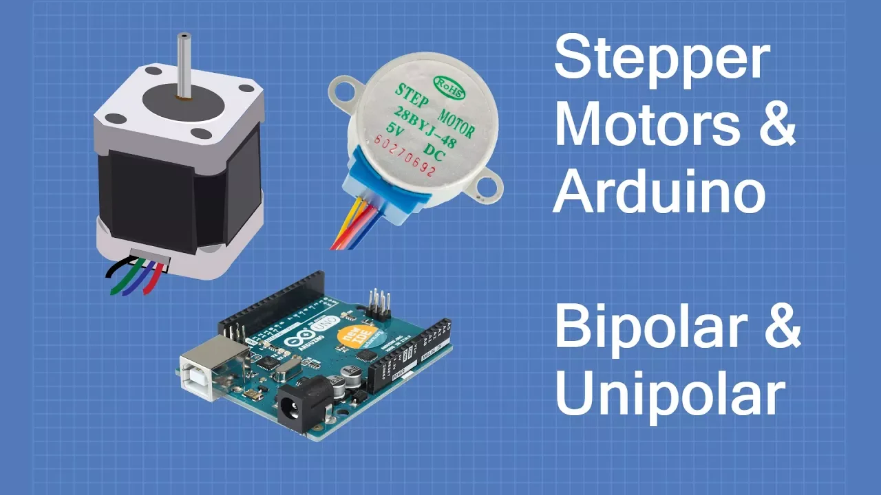
Bipolar stepper motors consist of two sets of coils with four wires total (two wires per coil). Unipolar stepper motors also have two coils but each coil has a center tap, resulting in five or six connections (the two center taps are often tied together). This fundamental difference in coil wiring arrangement affects how the motor is controlled and its performance characteristics.
Click to watch →
Motor de Pasos - Stepper Motor - Qué es y Cómo funciona - Parte1
78.6K
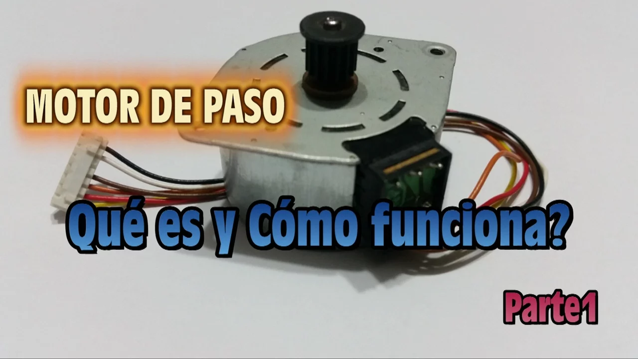
Bipolar stepper motors have four connection wires and consist of two coils in the stator with a permanent magnet rotor. Each coil has two terminals, requiring current direction changes through coils in a specific sequence to generate movement. They require a motor driver (such as a bridge H circuit) to control each coil individually. Unipolar stepper motors have five or six connection wires. In five-wire configurations, each coil has a central tap connected to a common wire. In six-wire configurations, each coil has its own central tap. The common wire connects to the power supply (typically 9.5V or 12V), while outer terminals connect to ground through a motor driver (such as ULN2803, L293D, or L298N). A unipolar motor with six wires can be converted to function as a bipolar motor by leaving common wires unconnected and connecting outer terminals of each coil together.
Click to watch →

Stepper Motors Simplified
8.7K
Stepper motors are classified into unipolar (with center-tapped coils requiring 5 wires) and bipolar (with reversible coils requiring 4 wires) types; unipolar motors operate by grounding phase coils in sequence (1→2→3→4 for clockwise, 4→3→2→1 for counterclockwise) while bipolar motors use an H-bridge configuration to reverse coil polarity for linear motion control.
Click to watch →
Stepper Motor Working Principles: Bipolar, Unipolar & More
156.6K
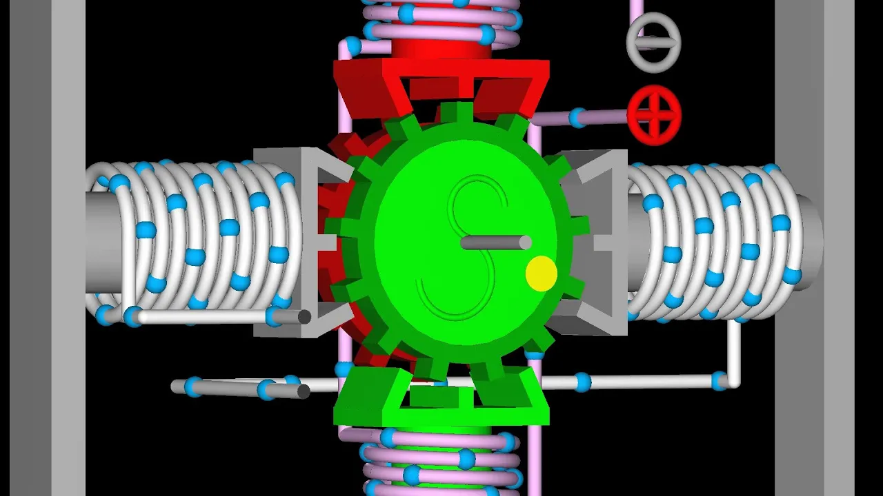
Bipolar stepper motors divide rotation into discrete steps using electromagnetic principles. The motor consists of a permanent magnet rotor interacting with electromagnet stators organized into phases. The left-hand rule determines magnetic polarity: wrap fingers in electron flow direction, thumb points to north pole. Torque is generated when stator fields attract rotor poles, causing rotation. The motor operates by sequentially energizing phases while reversing polarity, completing one full rotation in four steps with 90-degree steps for two-pole rotors or 30-degree steps for six-pole rotors. Counterclockwise rotation is achieved by traversing the operation table from right to left. Half-stepping doubles angular resolution by enabling both phases simultaneously before disabling the first phase, creating intermediate stable positions. Two-phase on excitation maintains both phases enabled throughout operation, providing higher torque but doubled current flow.
Click to watch →
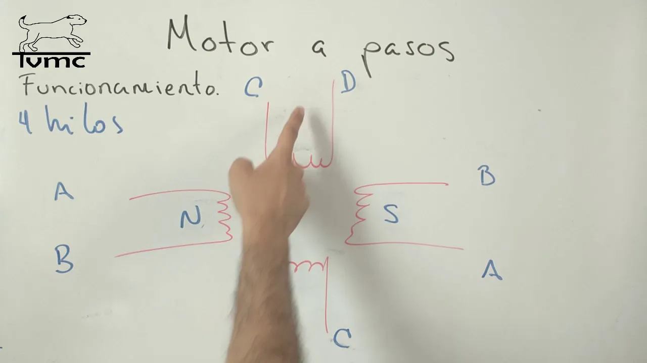
Cómo funciona un motor a pasos y cómo debes conectarlo al microcontrolador.
1.8K
Stepper motors differ fundamentally from DC motors: DC motors rotate at constant speed with high torque but lack precise control, while stepper motors excel at precise angular positioning through discrete steps. Stepper motors operate using electromagnetic principles where coils create electromagnets with north/south poles that attract or repel the permanent magnet rotor. For 90-degree rotation, two coils with opposite polarities create repulsion. Intermediate steps (45 degrees) are achieved by creating two poles of the same polarity that attract the rotor to a middle position. Motors can have 4 or 8 coils with various arrangements, achieving resolutions down to 1.8 degrees per step. Two main configurations exist: bipolar (interconnected coils, 4 wires) and unipolar (common wire, 5 wires). Motors with 6 wires typically have 2 common wires and 4 coil wires.
Click to watch →
Deep Dive
Understanding the necessity of motor drivers, specifically why microcontrollers cannot directly supply the current required to drive motors.
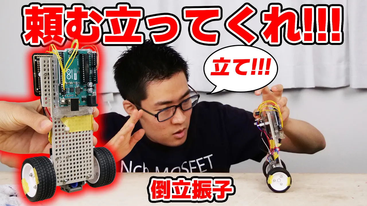
電気電子工学と制御工学の融合「倒立振子」を作ってみた! 難しすぎだろ!!
151.9K
A motor driver circuit is necessary between the microcontroller (Arduino) and the motor because the microcontroller cannot provide enough current to directly drive the motor. The motor driver amplifies the control signal from the microcontroller and supplies the high current required by the motor. Without a motor driver, the microcontroller would be damaged and the motor would not operate properly. The driver converts the low-power logic signals into high-power signals capable of driving the motor effectively.
Click to watch →
L293D - L293B Motor Sürücüleri ve PWM
91.9K
Motor drivers are essential because microcontrollers like Arduino cannot directly power motors. A typical DC motor draws 110-270mA under load, while Arduino digital pins can only safely supply 40mA maximum. Exceeding this limit can damage the microcontroller. Motor drivers provide the necessary current amplification to safely control motors from microcontroller pins.
Click to watch →
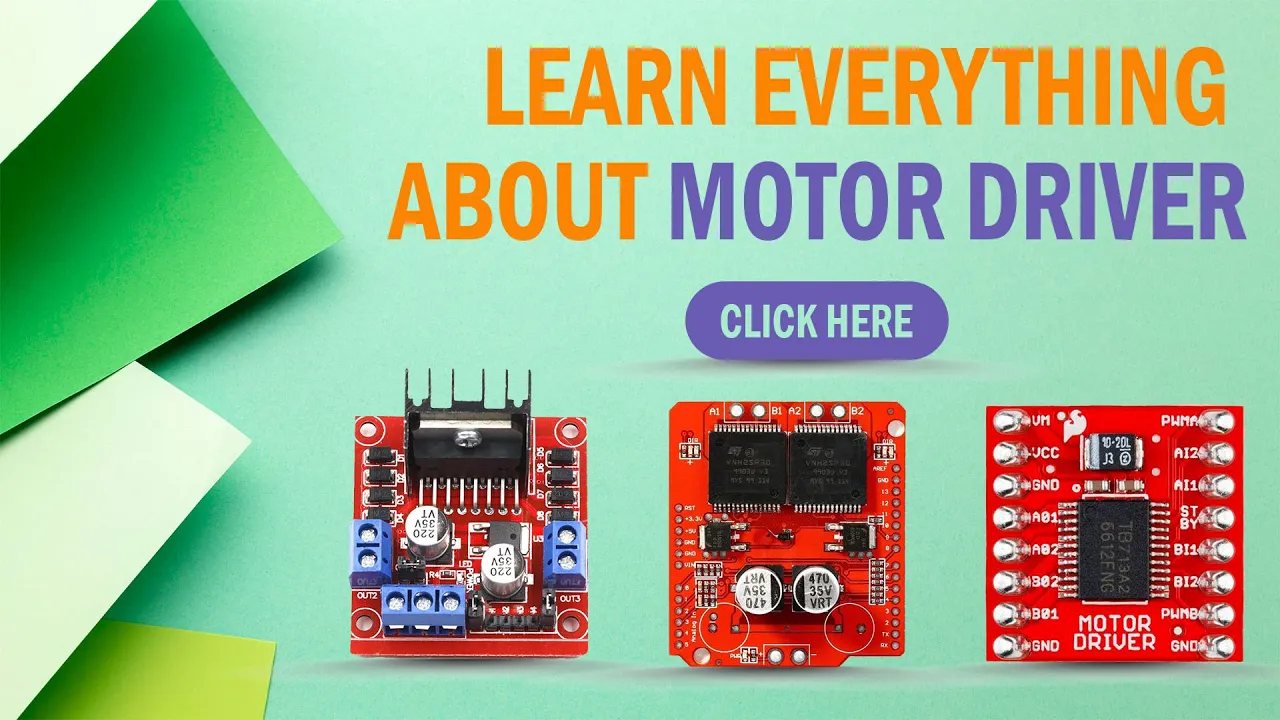
Learn Everything About Motor Driver | L293D, L293N | DC MOTOR DRIVER MODULE
777
Motor drivers are essential because microcontrollers cannot directly control DC motors. Microcontroller output pins typically provide only 3.3V to 5V at 20mA maximum, while normal DC motors require 12V at 1A or more. This significant power difference necessitates the use of motor driver modules to interface between microcontrollers and motors.
Click to watch →
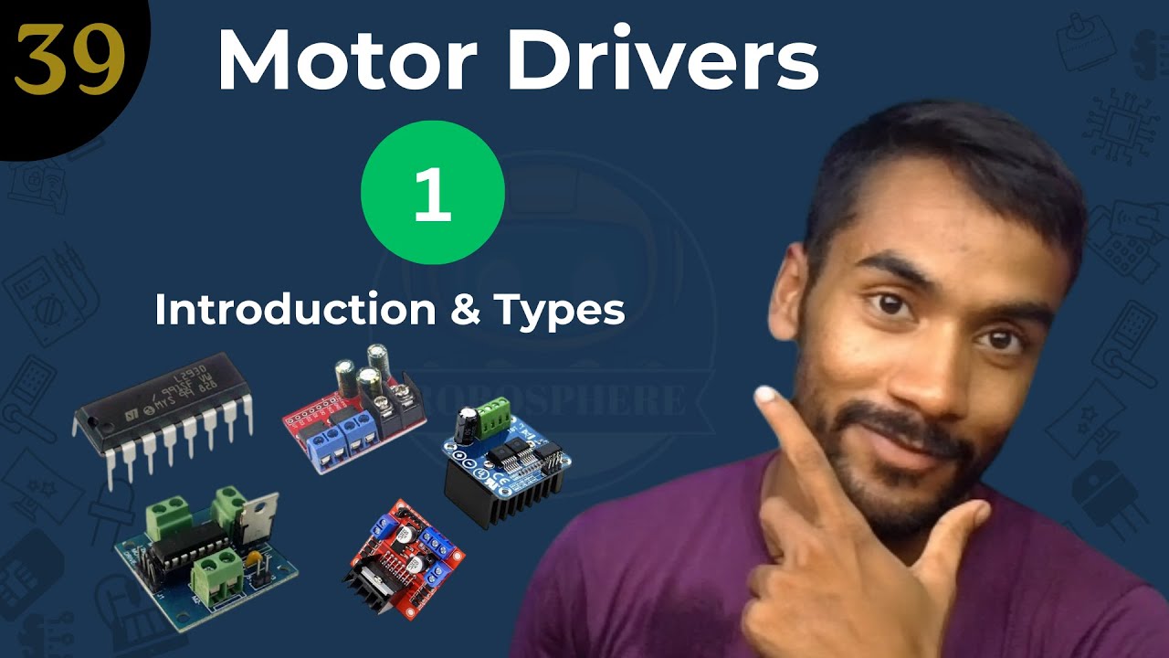
🎯 Lecture 39: Introduction to Motor Driver Modules | Arduino Tutorial
174
Motor drivers are essential because microcontrollers like Arduino cannot directly power DC motors. Arduino pins can only safely handle a maximum of 40 milliamperes of current at 5 volts. However, a typical DC motor requires at least 100 milliamperes, and larger motors can require several amperes. Direct connection would cause the Arduino to burn out or fail. Motor drivers act as intermediaries between the microcontroller and the motor, handling the high current requirements while allowing the microcontroller to control the motor's direction and speed.
Click to watch →

RoboCup Malaysia Junior Outreach 2024 (Online session)
181
Robot controllers consist of a microcontroller (the brain) and a motor driver (to drive motors). The motor driver is necessary because microcontrollers cannot directly drive motors due to current requirements. Different platforms include Arduino (Mega 328), Raspberry Pi Pico, and Microbit. The Microbit Motion Bit supports up to 4 motors, while others support 2 motors. The Motion Pro version supports 12V motors.
Click to watch →
Prerequisite Knowledge
- Concept 01Basic Arduino programming, including familiarity with IDE setup, GPIO control, and basic functions like digitalWrite() and delay().
- Concept 02Fundamental concepts of DC electronics, particularly voltage, current, breadboard wiring, and the importance of a common ground.
- Concept 03The operational theory of stepper motors, including how bipolar stepper motors differ from standard DC or servo motors in terms of coils and phases.
- Concept 04Understanding the necessity of motor drivers, specifically why microcontrollers cannot directly supply the current required to drive motors.
Subsequent Learning
- Step 01Configuring microstepping on the A4988 (using MS1, MS2, and MS3 pins) to achieve smoother motion, lower noise, and higher positional resolution.
- Step 02Setting and measuring the current limit on the A4988 driver using its onboard potentiometer and a multimeter to prevent overheating.
- Step 03Implementing advanced stepper motor control libraries, such as AccelStepper, to handle acceleration, deceleration, and non-blocking multi-axis control.
- Step 04Integrating stepper motors into complex real-world applications, such as DIY 3D printers, CNC routers, or automated camera sliders using GRBL firmware.
Opening
First Insight
Deep Dive
Turning Point
Conclusion
Opening
0:41Playing Section
- 1
Visual and audio introduction setting the tone.
- 2
Brief musical sequence establishes initial atmosphere.
- 3
No spoken content yet; focus on sensory engagement.
Modern Trinamic (TMC) Drivers as Superior Alternatives to the A4988
While the A4988 driver is a classic, budget-friendly starting point for learning stepper motor control, it represents legacy technology with significant limitations in modern mechatronics. The primary criticisms of the A4988 are its high operational noise, harsh vibrations, and low energy efficiency, stemming from its limited microstepping resolution (maximum 1/16 step) and basic current-chopping method. Modern alternatives, such as Trinamic (TMC) drivers (e.g., TMC2208 or TMC2209), offer a vastly superior paradigm. TMC drivers utilize advanced technologies like StealthChop™ for near-silent operation, SpreadCycle™ for smooth motion, and internal interpolation up to 1/256 microsteps. Additionally, they feature StallGuard™ (sensorless load detection and homing) and CoolStep™ (dynamic current control to reduce heat generation). For students, relying solely on the A4988 can obscure these crucial, modern industry standards. Exploring TMC drivers provides a broader, more contemporary understanding of precise, silent, and efficient motion control required in professional robotics and modern 3D printing.
Deep Dive
Configuring microstepping on the A4988 (using MS1, MS2, and MS3 pins) to achieve smoother motion, lower noise, and higher positional resolution.
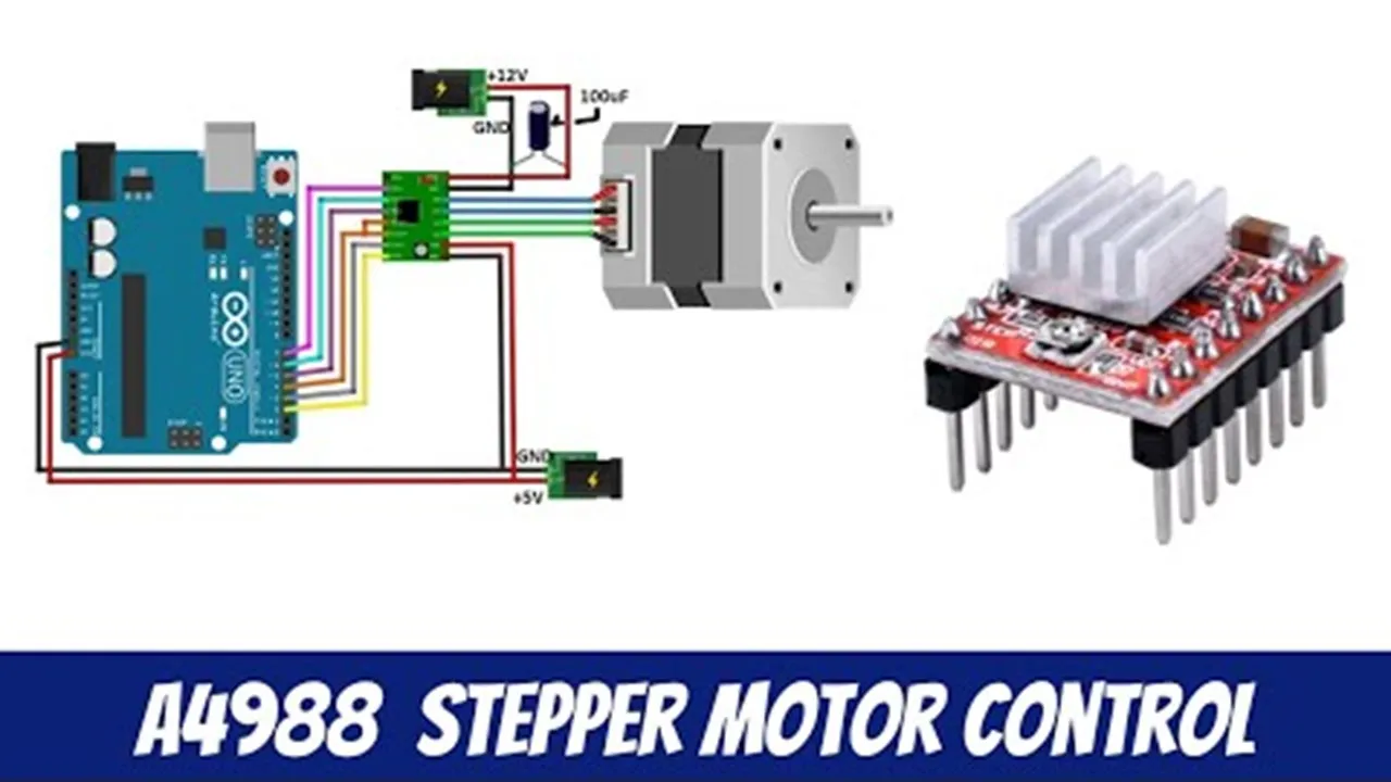
A4988 Stepper Motor Controller - Arduino & NodeMCU
165.1K
The A4988 driver uses three pins (MS1, MS2, MS3) to configure microstepping modes. Full steps require all pins disconnected or low. Half steps use MS1=HIGH, others LOW. Quarter steps use MS2=HIGH, others LOW. Eighth steps use MS1=HIGH and MS2=HIGH. Sixteenth steps use all three pins HIGH. Each mode increases the number of steps per revolution: full steps = 200, half steps = 400, quarter steps = 800, eighth steps = 1600, sixteenth steps = 3200. Higher microstepping provides smoother motor movement by dividing each step into smaller increments.
Click to watch →
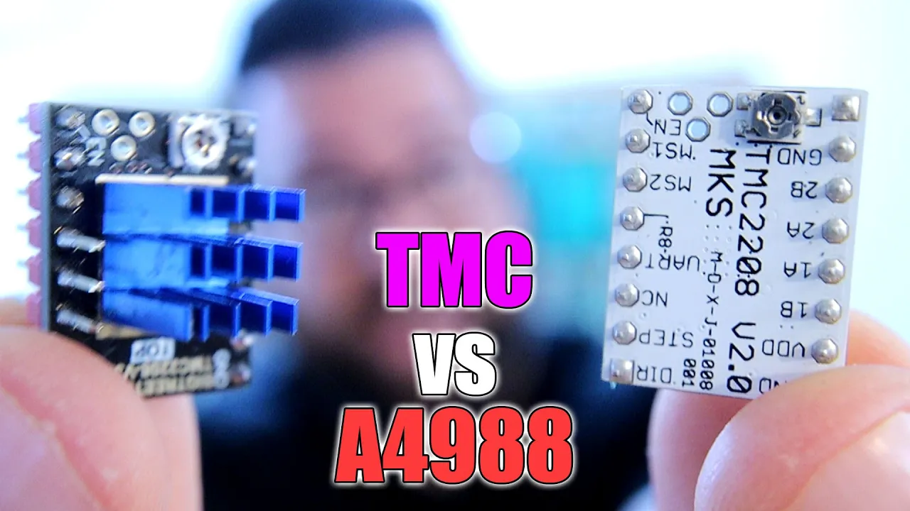
Stepper Drivers A4988 vs TMC SILENT drivers - Sound & Signals
61.6K
The A4988 stepper motor driver uses MS1, MS2, and MS3 pins to configure microstepping modes. By connecting VCC to these pins according to a reference table, users can select between full step and up to 16 microsteps. Full step produces a square wave signal with significant vibration and noise. Quarter step increases the number of steps visible on an oscilloscope and reduces sound. Sixteen microsteps further smooths the signal but still does not produce a perfect sinusoidal wave.
Click to watch →
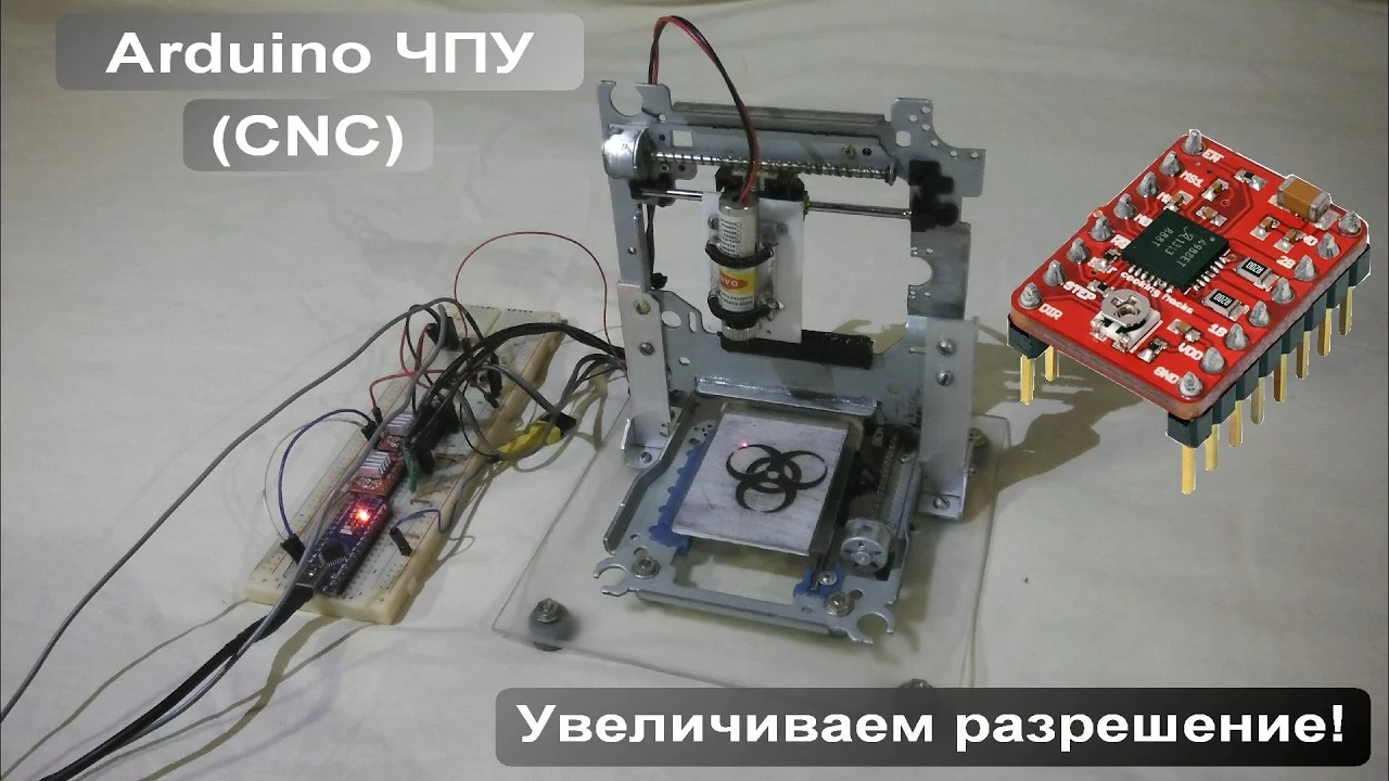
Лазерный ЧПУ гравер / Увеличиваем разрешение "микрошаг"
137.4K
Microstepping is a software technique that divides motor step angles into smaller increments (2, 4, 8, 16 times), enabling finer control and higher resolution. The A4988 driver supports microstepping up to x16, reducing step angles by 16 times. Configuration uses MS1, MS2, MS3 pins: all grounded for full step mode, all connected to positive for x16 microstepping. The driver provides adjustable current limiting (1A without heatsink, 2A with), enabling higher voltage operation for faster step response. Protection features include overheat, short circuit, and overload protection.
Click to watch →
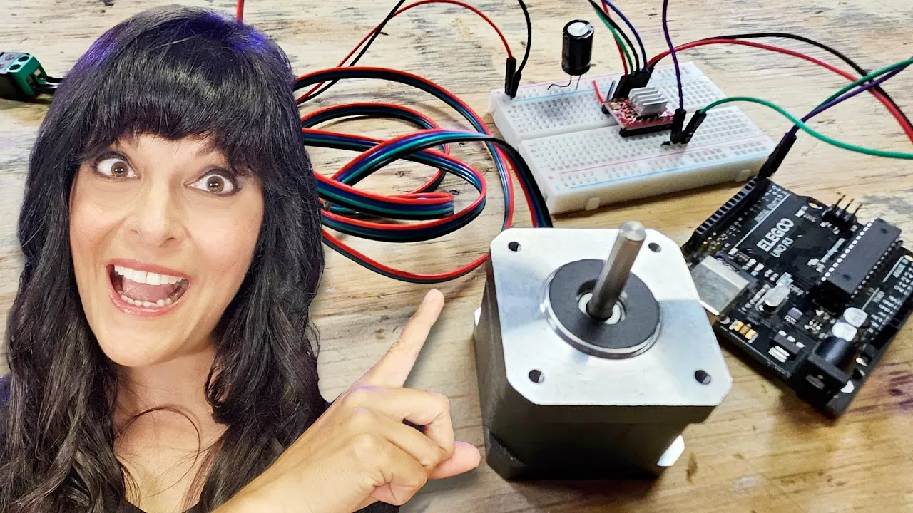
Control a NEMA 17 Stepper Motor with A4988 Driver and Arduino - Full Guide
134.3K
Microstepping divides each full step into smaller increments for smoother rotation. The A4988 supports quarter-step, eighth-step, and sixteenth-step modes through combinations of MS1, MS2, and MS3 pins. Default mode is full step with no connections. Quarter-step requires MS1=LOW, MS2=HIGH, MS3=LOW. Each microstep mode produces approximately half the torque of the previous mode but provides smoother motion. The example uses quarter-step with delayMicroseconds(2000) to demonstrate very slow, smooth rotation where each step moves only a quarter of a full step distance.
Click to watch →
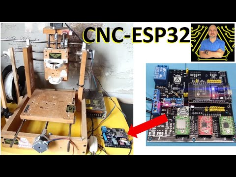
✅ Maquina CNC de Control Numérico con ESP32, Cómo diseñamos el PCB
60.6K
The A4988 stepper motor driver supports multiple microstepping modes through its MS1, MS2, and MS3 configuration pins. These pins determine whether the motor operates in full step, half step, quarter step, eighth step, or sixteenth step mode. The configuration is achieved by connecting these pins to either VCC (positive) or GND (ground). For example, connecting all three pins to VCC enables 1/16 microstepping, while different combinations produce other stepping resolutions. This allows designers to optimize motor performance for their specific CNC application requirements.
Click to watch →
Deep Dive
Setting and measuring the current limit on the A4988 driver using its onboard potentiometer and a multimeter to prevent overheating.
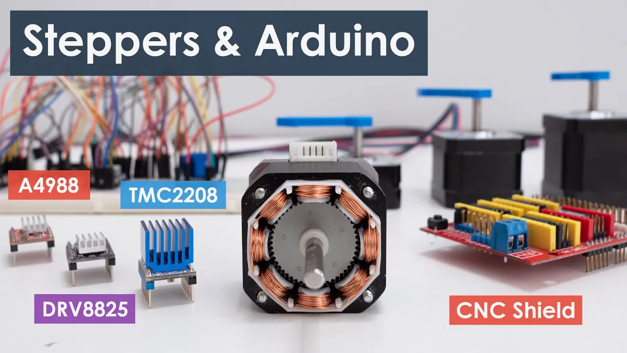
Controlling Stepper Motors with Arduino: A Guide
1.6M
The A4988 driver has a trimmer potentiometer for adjusting current limit. Two methods exist: Method 1 measures reference voltage across the potentiometer and ground using a multimeter, then calculates current limit using I = Vref / (RCS), where RCS is the current sensing resistance (typically 0.05, 0.1, or 0.2 ohms). Method 2 connects an ammeter in series with one motor coil while powering the driver in full-step mode (with DMS pins disconnected), noting that coil current reaches only 70% of the actual current limit in this mode.
Click to watch →
Control a NEMA 17 Stepper Motor with A4988 Driver and Arduino - Full Guide
134.3K
Proper current limiting is essential to prevent motor damage. The process involves: disconnecting the stepper motor; connecting a multimeter set to voltage measurement; attaching alligator clips to the potentiometer adjustment screw and ground; turning the potentiometer while monitoring the reading; calculating the target reference voltage using Vref = I_limit × 8 × R_sense (where R_sense is typically 0.1 ohms for the R100 label); adjusting until reaching the desired value (e.g., 1.2V for 1.5A limit); and verifying the setting before reconnecting the motor. Always set slightly below the maximum recommended value.
Click to watch →
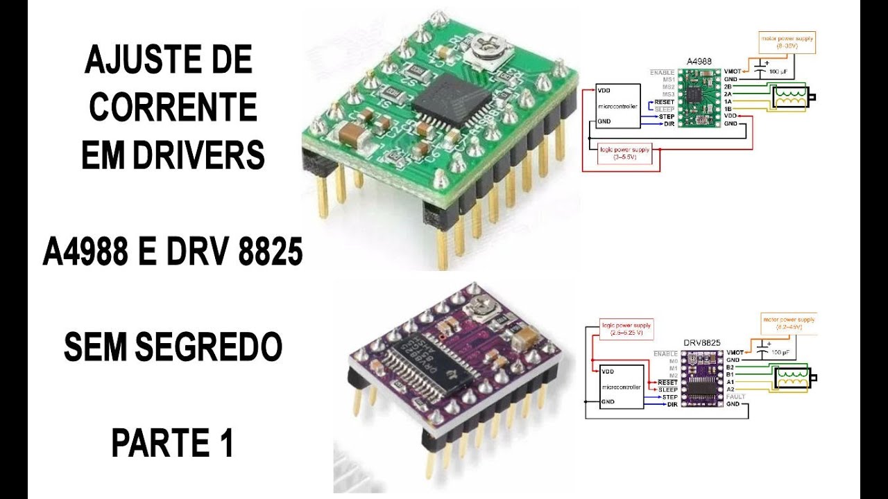
Ajuste de Corrente drivers A4988 e DRV8825 sem SEGREDO #1!
18.9K
This section explains the current adjustment formula for A4988 driver: Reference Voltage = (Motor Current × Desired Percentage × Register Value) / 3. The A4988 has three register values: 0.05, 0.1, and 0.2. The presenter demonstrates practical application by measuring a motor consuming 0.9A at 80% usage with register 0.2, calculating 0.84V reference voltage. The presenter shows how to measure with a multimeter on 20V scale, connecting negative to source negative and positive to the adjustment pin. The presenter demonstrates adjusting to 0.84V, then lowering to 0.702V when the motor overheats, showing how to find the optimal setting.
Click to watch →
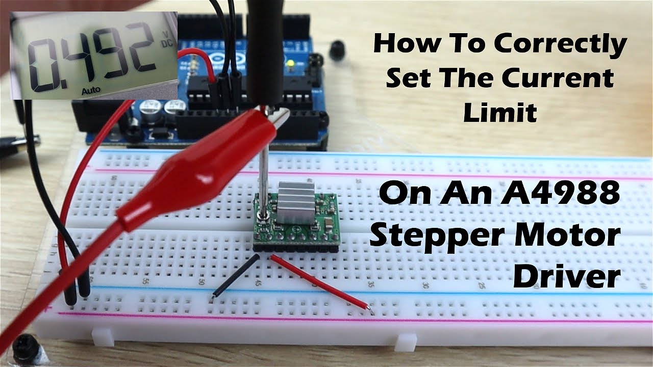
How To Correctly Set The Motor Current Limit On An A4988 Stepper Motor Driver
139.4K
To correctly set the motor current limit on an A4988 stepper motor driver, calculate the reference voltage using the formula Vref = Imax × 8 × R_sense, where Imax is the motor's maximum current (from datasheet) and R_sense is the current sensing resistance (typically 0.06Ω), then adjust the potentiometer on the driver board while bridging the sleep and reset pins and powering the logic circuit; for example, with a motor rated at 0.9A, the reference voltage should be set to approximately 0.49V.
Click to watch →
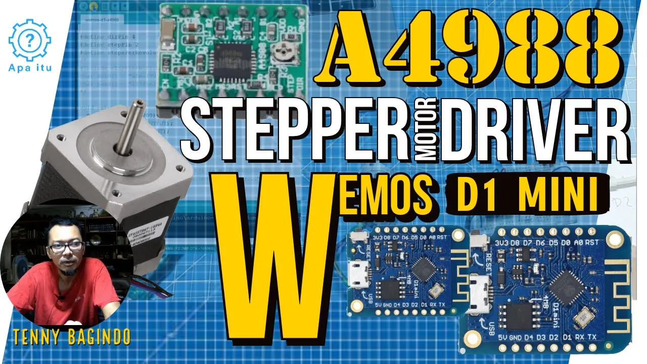
A4988 Stepper Driver pada Wemos D1 Mini (Subtittled)
3.8K
The A4988 uses current limiting through Vref and sense resistors (Rs). The formula ITripmax = Vref / (8 × Rs) calculates maximum current. For example, with Vref = 0.26V and Rs = 0.1Ω, maximum current is 0.33A. A safety factor of 0.7-0.8 should be applied. The Vref is adjusted using a potentiometer and measured with a multimeter. The chip includes current sensing resistors to monitor and limit motor current, preventing damage from excessive current.
Click to watch →
Deep Dive
Implementing advanced stepper motor control libraries, such as AccelStepper, to handle acceleration, deceleration, and non-blocking multi-axis control.
Controlling Stepper Motors with Arduino: A Guide
1.6M
The AccelStepper library provides advanced features including speed, acceleration, and deceleration control, target position setting, and multi-motor control. Key functions include setSpeed(), runSpeed(), moveTo(), and runToPosition(). The library supports different driver types and offers maximum reliable speed of ~1000 steps/sec. Acceleration/deceleration is enabled via setAcceleration(), with moveTo() setting targets and runToPosition() moving with acceleration (blocking function). For non-blocking operation, use run() within a while loop. The MultiStepper class enables synchronized multi-motor control where motors reach targets simultaneously regardless of travel distance, by creating an array of target positions and assigning to moveTo(). Note: MultiStepper does not support acceleration/deceleration.
Click to watch →
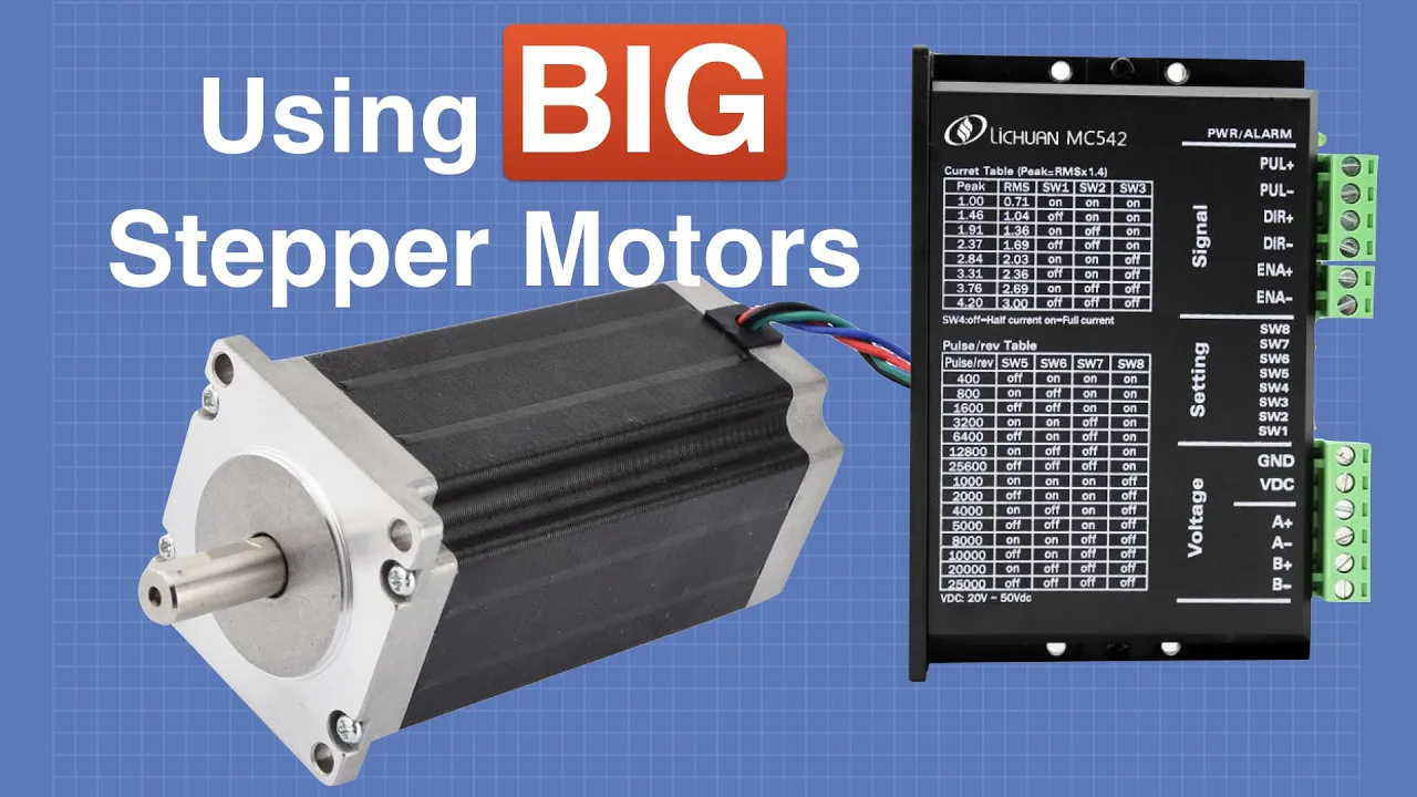
Big Stepper Motors with Arduino
1.3M
The AccelStepper library provides advanced stepper motor control features including acceleration and deceleration profiles. To use it with a motor driver: create a stepper object specifying the driver type (1 for our modules), pulse pin, and direction pin. Example code includes functions like moveTo() and run() for automated movement. The bounce example demonstrates moving between limits with smooth acceleration and deceleration. Microstepping settings affect both speed and torque - different microstepping modes provide different torque characteristics. This library simplifies complex motor control tasks compared to writing raw pulse generation code.
Click to watch →
![🔥[FA-DUINO#33] 산업용 아두이노(arduino)와 TB6600으로 스탭모터(NEMA17) 제어해보기!(1)](https://i.ytimg.com/vi/iMD2FIcQl8c/maxresdefault.jpg)
🔥[FA-DUINO#33] 산업용 아두이노(arduino)와 TB6600으로 스탭모터(NEMA17) 제어해보기!(1)
9K
This segment introduces the critical distinction between blocking and non-blocking code in Arduino programming. Blocking code halts the entire Arduino system while executing, preventing the Arduino from performing other tasks like reading sensors or responding to user inputs. The presenter demonstrates how a loop with a delay or long-running operation freezes the main loop. The AccelStepper library is introduced as a solution for non-blocking stepper motor control. The library uses hardware timers to generate precise pulse signals without blocking the main program. The presenter demonstrates installing the library through the Arduino IDE's Library Manager and configuring it for the TV6600 driver. The library maintains an internal position counter that tracks the motor's current position in steps. The segment covers the runSpeedToPosition() function for constant speed movement and explains how to set the speed in steps per second.
Click to watch →
Stepper Motors with Arduino - Controlling Bipolar & Unipolar stepper motors
2.3M
The AccelStepper library provides more advanced motor control capabilities than the standard stepper library, including acceleration and deceleration functions. It requires installation through the Arduino Library Manager. The library allows defining different step modes (full steps and half steps) for multiple motors simultaneously, with separate configuration for each motor's maximum speed, acceleration, and target positions.
Click to watch →

057 Stepper motors Part 5 Using the AccelStep library
17K
The AccelStep library provides advanced control for stepper motors by enabling acceleration and deceleration profiles, allowing motors to smoothly increase and decrease speed rather than moving at constant rates. This library supports multiple motor configurations, non-blocking operation (allowing other Arduino functions to run simultaneously), and provides functions to set maximum speed, acceleration rates, and start speeds. The library tracks motor position and distance to destination, enabling precise control over motor movement while maintaining system responsiveness.
Click to watch →
Deep Dive
Integrating stepper motors into complex real-world applications, such as DIY 3D printers, CNC routers, or automated camera sliders using GRBL firmware.
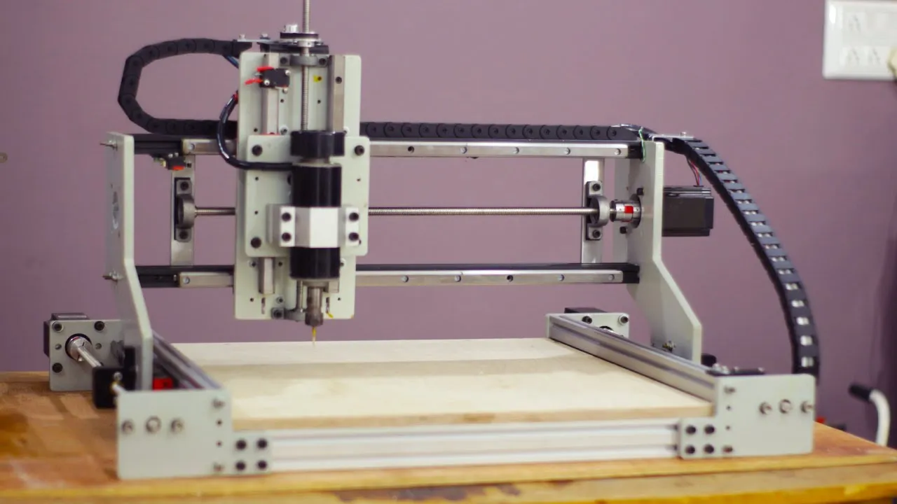
DIY CNC router | Arduino + GRBL + NEMA23
509.6K
A DIY CNC router can be constructed using NEMA23 stepper motors controlled by an Arduino Nano running GRBL firmware, with a custom PCB shield featuring TB6600 drivers and screw terminals for direction and pulse signals; this setup supports advanced CNC operations including hold, resume, and abort functions for precise material cutting and engraving applications.
Click to watch →
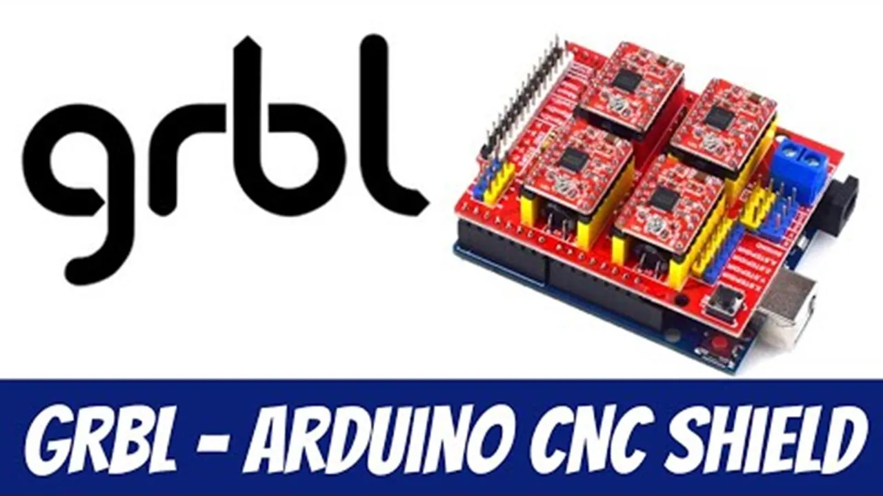
GRBL and Arduino CNC Shield Setup Guide for Beginners
264.6K
GRBL is a free open-source motion control software that enables Arduino boards to operate CNC machines by controlling stepper motors through the Arduino CNC Shield, which provides pre-wired connections for up to four stepper motor drivers and includes pins for limit switches, spindle control, and other machine functions; the system requires installing GRBL firmware on an Arduino Uno, configuring the CNC Shield according to the machine's axis configuration, and using G-code sender software like UGS to send commands and control the machine's movements.
Click to watch →
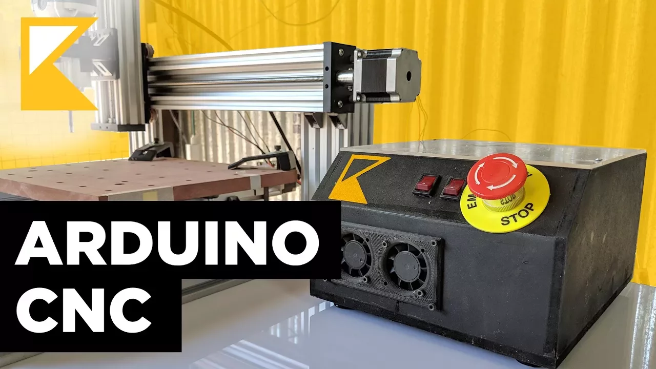
Build a CNC Controller with Arduino, TB6600 and GRBL
354.2K
This video guides viewers through configuring a CNC controller using an Arduino Uno, TB6600 stepper motor driver, and GRBL firmware. The author, having assembled a C-Beam CNC mechanical frame from a kit, details the electronic components required to complete the system. These include stepper motors, a TB6600 driver for motor control, an Arduino Uno as the microcontroller, a suitable power supply, an emergency stop switch, a router with power switch, 4-pin connectors, and an AC power connector. The video references external tutorials for identifying stepper motor wiring, installing and configuring GRBL firmware, using Universal Gcode Sender for communication, and operating Easel for G-code generation. The author emphasizes that these details were previously scattered across sources, prompting them to compile a comprehensive guide. The tutorial is presented as a written resource with downloadable schematics, intended to simplify the setup process for others attempting similar builds. The focus is on hardware selection and integration, not on circuit design or firmware coding beyond referencing GRBL.
Click to watch →
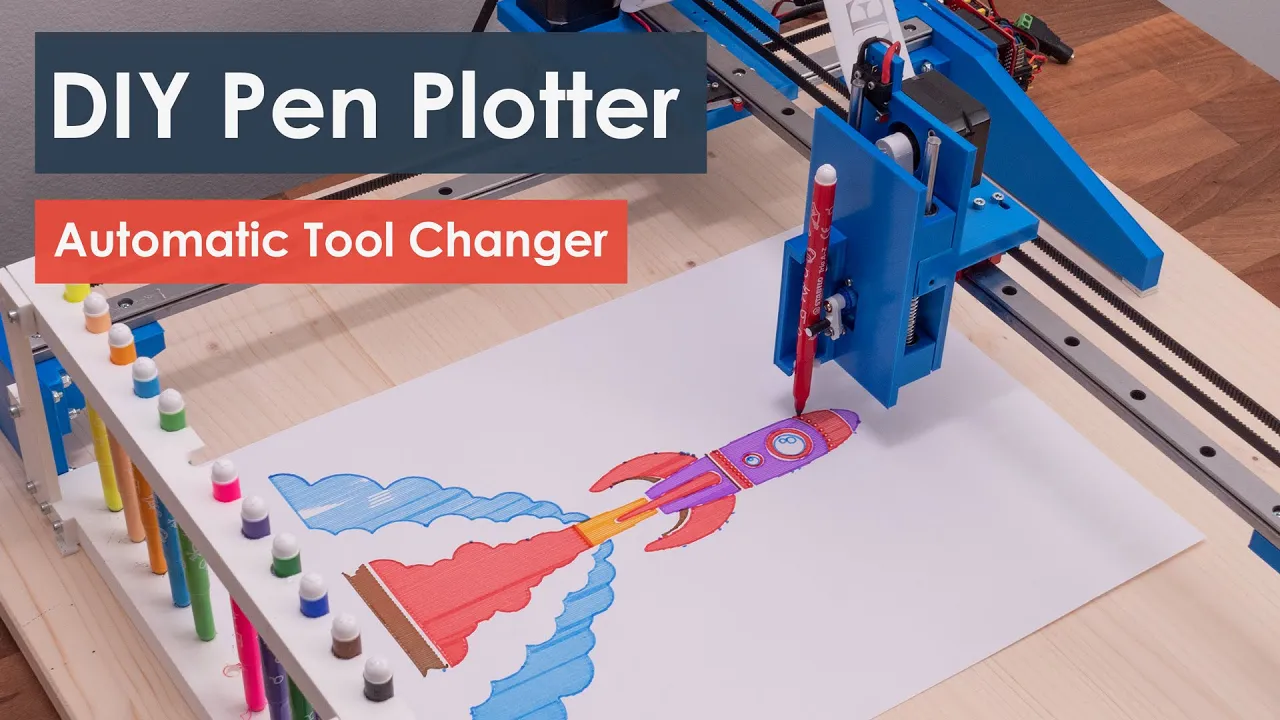
DIY Pen Plotter with Automatic Tool Changer | Arduino based CNC Drawing Machine
494.1K
To enable CNC functionality, install modified GRBL firmware (GRBL Servo) for servo control, which changes digital pin 11's PWM frequency from 1kHz to 50Hz for standard RC servos. Install this firmware in the Arduino IDE library folder and modify config.h to enable tree access homing. Use GRBL Plotter software (open-source) for controlling the plotter, which includes a graphic converter for generating G-code from images. Configure essential parameters: travel resolution (steps per millimeter) depends on stepper motor type and transmission; for this machine, X/Y require 80 steps/mm for accuracy while Z uses 40 steps/mm. Set parameter 23 to 0 for limit switch location, maximum feed rate, acceleration, and parameter 1 to 255 to keep steppers active continuously. Note that continuous Z-axis operation may require adjusting driver current limits to prevent overheating.
Click to watch →
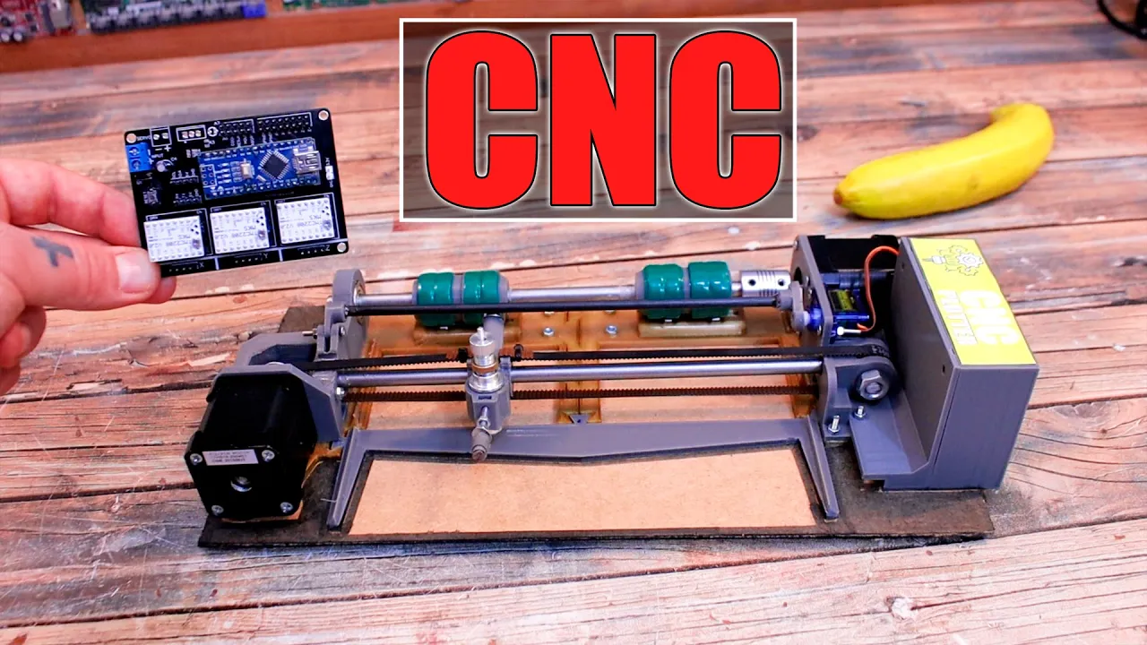
GRBL PCB Shield - CNC Plotter | Vinyl Cutter
158.1K
This video demonstrates how to build a 2-axis CNC plotter/vinyl cutter using an Arduino Nano, GRBL firmware, and a custom-designed PCB shield that interfaces with stepper motor drivers (A4988 or TMC2208) and a servo motor for Z-axis height control, with the machine assembled from 3D-printed parts, metal rods, 608 bearings, GT2 belts, and a vinyl cutter blade mounted on a bearing for smooth material cutting.
Click to watch →
Opening
First Insight
Deep Dive
Turning Point
Conclusion
Opening
0:41- 1
Visual and audio introduction setting the tone.
- 2
Brief musical sequence establishes initial atmosphere.
- 3
No spoken content yet; focus on sensory engagement.
Modern Trinamic (TMC) Drivers as Superior Alternatives to the A4988
While the A4988 driver is a classic, budget-friendly starting point for learning stepper motor control, it represents legacy technology with significant limitations in modern mechatronics. The primary criticisms of the A4988 are its high operational noise, harsh vibrations, and low energy efficiency, stemming from its limited microstepping resolution (maximum 1/16 step) and basic current-chopping method. Modern alternatives, such as Trinamic (TMC) drivers (e.g., TMC2208 or TMC2209), offer a vastly superior paradigm. TMC drivers utilize advanced technologies like StealthChop™ for near-silent operation, SpreadCycle™ for smooth motion, and internal interpolation up to 1/256 microsteps. Additionally, they feature StallGuard™ (sensorless load detection and homing) and CoolStep™ (dynamic current control to reduce heat generation). For students, relying solely on the A4988 can obscure these crucial, modern industry standards. Exploring TMC drivers provides a broader, more contemporary understanding of precise, silent, and efficient motion control required in professional robotics and modern 3D printing.
Basic Arduino programming, including familiarity with IDE setup, GPIO control, and basic functions like digitalWrite() and delay().
Fundamental concepts of DC electronics, particularly voltage, current, breadboard wiring, and the importance of a common ground.
The operational theory of stepper motors, including how bipolar stepper motors differ from standard DC or servo motors in terms of coils and phases.
Understanding the necessity of motor drivers, specifically why microcontrollers cannot directly supply the current required to drive motors.
Configuring microstepping on the A4988 (using MS1, MS2, and MS3 pins) to achieve smoother motion, lower noise, and higher positional resolution.
Setting and measuring the current limit on the A4988 driver using its onboard potentiometer and a multimeter to prevent overheating.
Implementing advanced stepper motor control libraries, such as AccelStepper, to handle acceleration, deceleration, and non-blocking multi-axis control.
Integrating stepper motors into complex real-world applications, such as DIY 3D printers, CNC routers, or automated camera sliders using GRBL firmware.
28.5K views380likes4:45@passiontechklmOriginal Release: 2021-05-02
[Music] [Music] [Music] [Music] so [Music] [Music] [Music] [Music] [Music] [Music] so [Music] so [Music] you
Up Next

16:02
Building a Polargraph Drawing Machine from an Old 3D Printer
@Ruforge
935 views•2024-08-11

12:54
Triumph of Orthodoxy Icon: Byzantine Art & History Explained
@BenCallan
2.1K views•2024-08-06

9:49
FastAPI vs Flask vs Django: Choosing the Right Python Web Framework
@TechWithTim
302.5K views•2024-05-26

1:42
Game of Thrones Opening Credits: A Cinematic Analysis
@gameofthrones
46.3M views•2011-04-18
Related Study Plans & Knowledge Roadmaps
Structured learning paths in General & Interdisciplinary Studies
general-studies
Elevator Engineering: History, Physics & Cities
01From Hoists to Safety Brakes: The Dawn of Vertical Lift
02Hydraulic vs. Traction: The Engineering Physics of Elevators
03Modern Speed, Safety, and Algorithms
+ 2 more learning modules
12h5 modules
Explore Roadmap
general-studies
Rubber: Material Science, History & Geopolitics
01Origins of Natural Rubber & Mesoamerican History
02The Chemistry of Natural Rubber & Vulcanization
03The Geopolitics of the Rubber Boom & Colonization
+ 2 more learning modules
12h5 modules
Explore Roadmap
general-studies
Containerization: Evolution, Logistics & Trade
01Ancient Trade & Bulk Cargo: Amphorae to Barrels
02The Industrial Revolution & Cardboard Packaging
03The Containerization Revolution: Malcom McLean
+ 2 more learning modules
12h5 modules
Explore Roadmap
general-studies
Textile Tech: Evolution, Labor & Global Impact
01Pre-Industrial Textiles: Handloom & Cottage Industry
02Mechanization: The Spinning Jenny to the Power Loom
03The Factory System & Global Labor Transformation
+ 2 more learning modules
10h5 modules
Explore Roadmap