














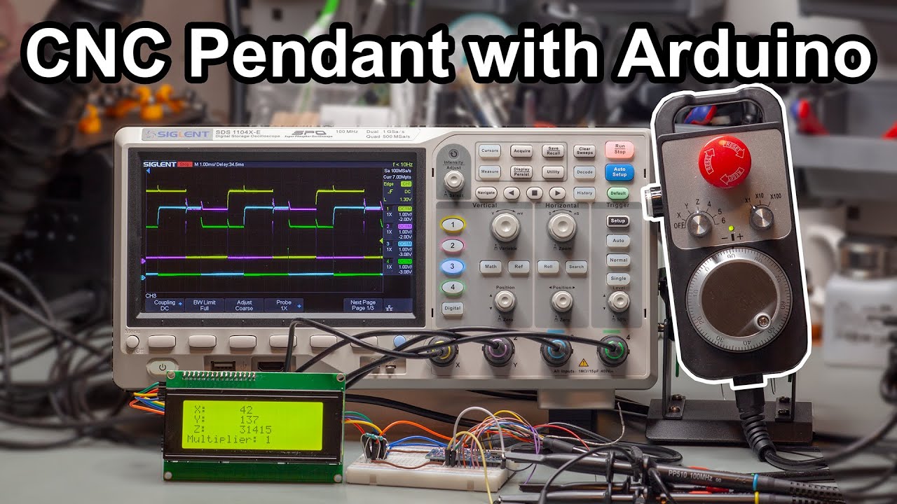


A rotary encoder is an incremental position sensor that generates two out-of-phase signals (CLK and DT) to detect rotational direction and position changes; when interfaced with Arduino, it should be connected to interrupt pins (pins 2 and 3 on Uno/Nano) rather than polling, as interrupts ensure reliable detection even when the processor is busy, and the Encoder library simplifies implementation by automatically handling signal reading and position tracking.
Using Rotary Encoders with Arduino: Interrupts and Code
Added:Basic Arduino programming concepts, including the setup() and loop() functions, GPIO configuration, and digital input reading.
Fundamental electronics and wiring concepts, specifically how pull-up or pull-down resistors prevent floating inputs.
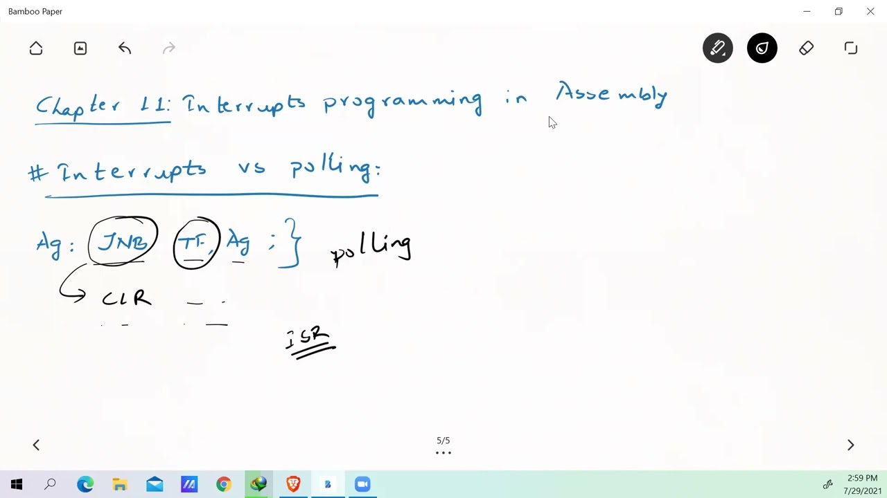
An introductory understanding of hardware interrupts versus polling methods in microcontrollers.
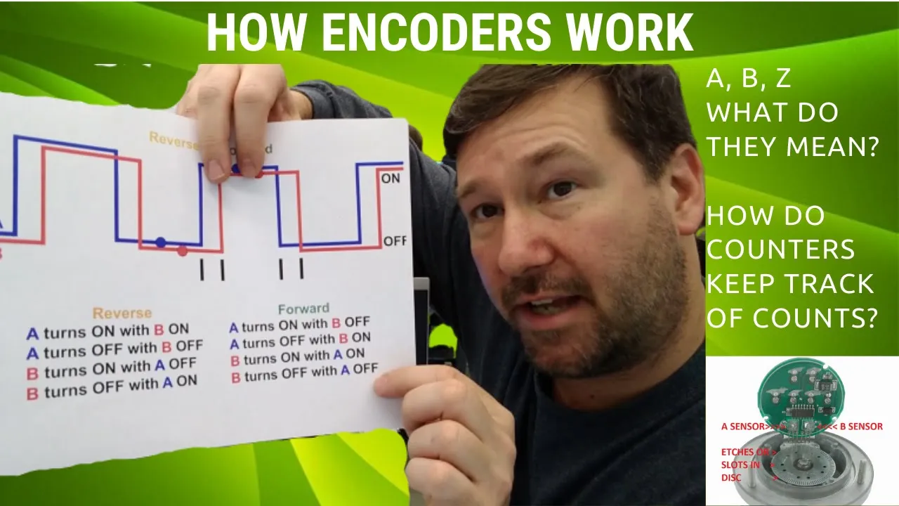
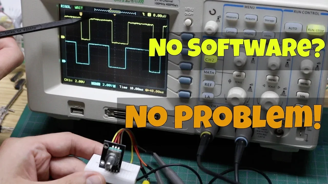
The basic mechanical and electrical operation of a quadrature rotary encoder (how shifting A and B phases indicate direction).
Implementing software and hardware debouncing techniques to eliminate mechanical noise from the encoder contacts.
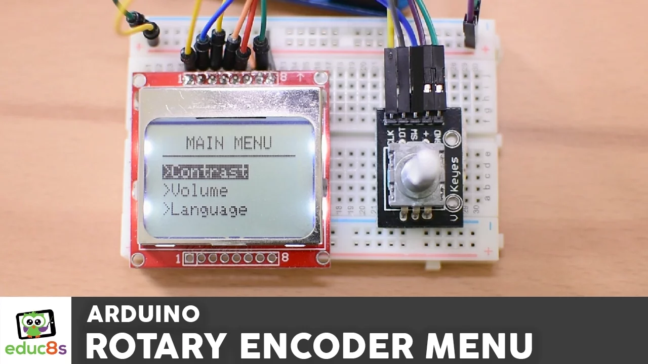
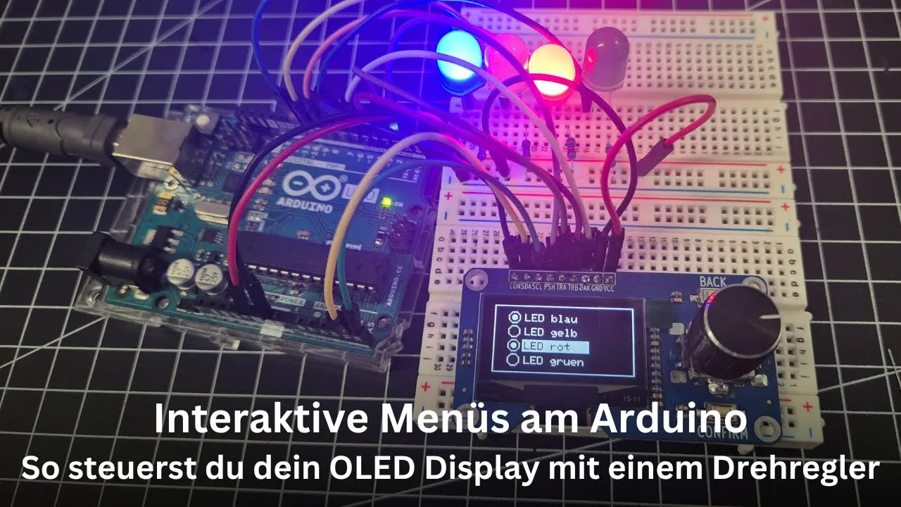
Building interactive menus and user interfaces (HMI) using rotary encoders and LCD/OLED displays.
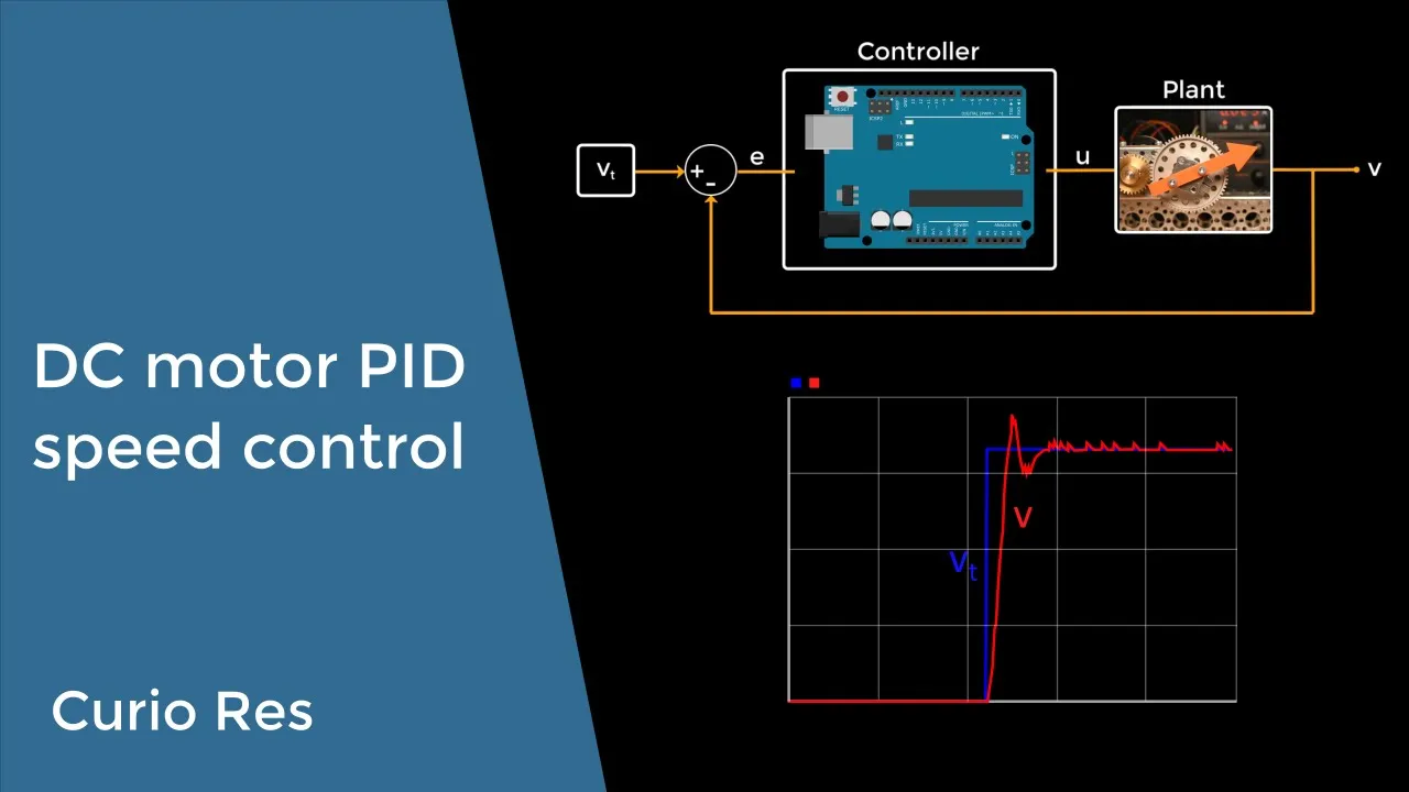
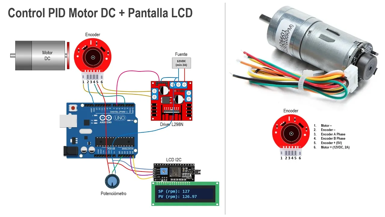
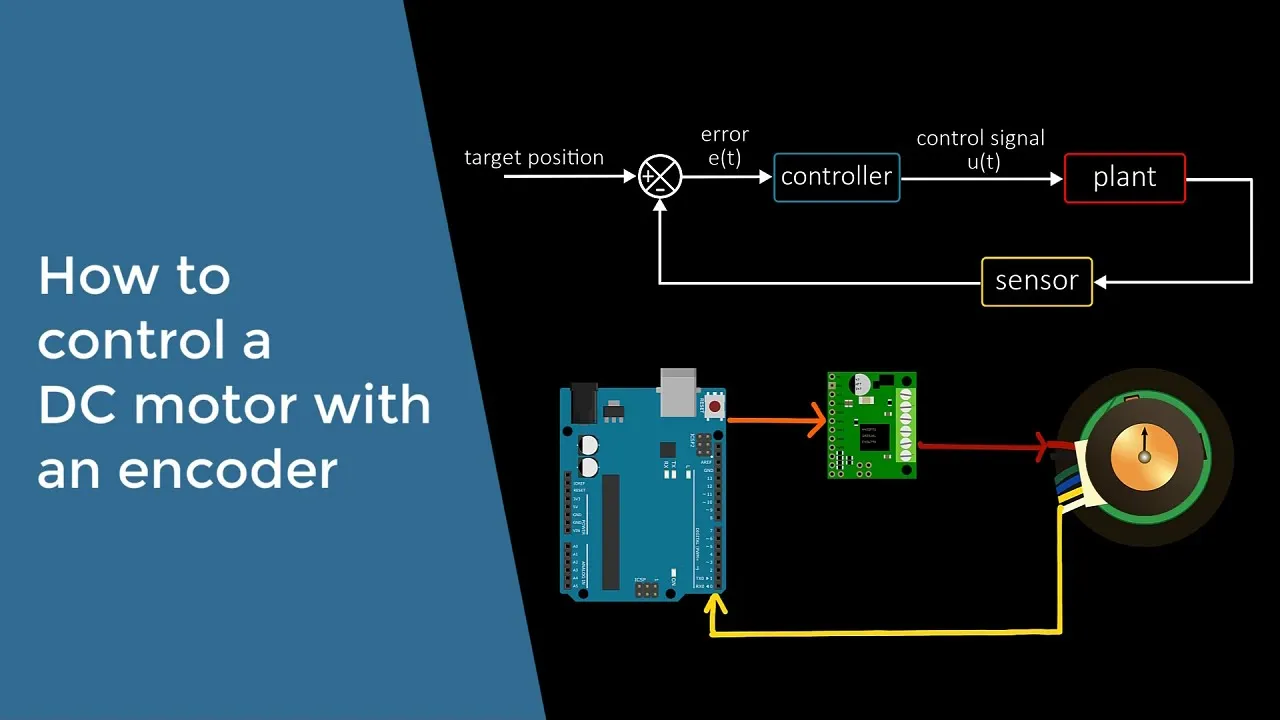
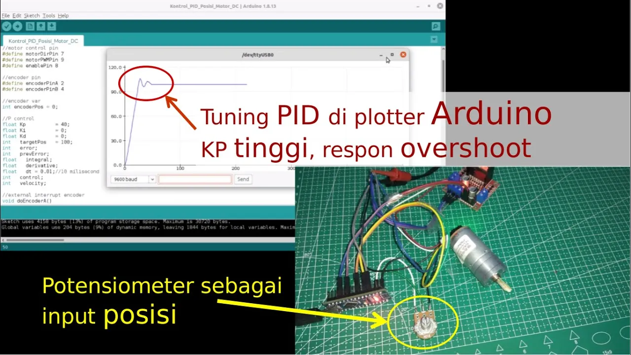
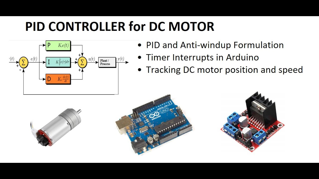
Developing closed-loop control systems, such as using encoder feedback for precise DC motor speed and position control (PID control).
Exploring advanced interrupt handling, including direct port manipulation and utilizing hardware-based quadrature encoder interface (QEI) modules.
6.4K views85likes8:10Original Release: 2021-05-09
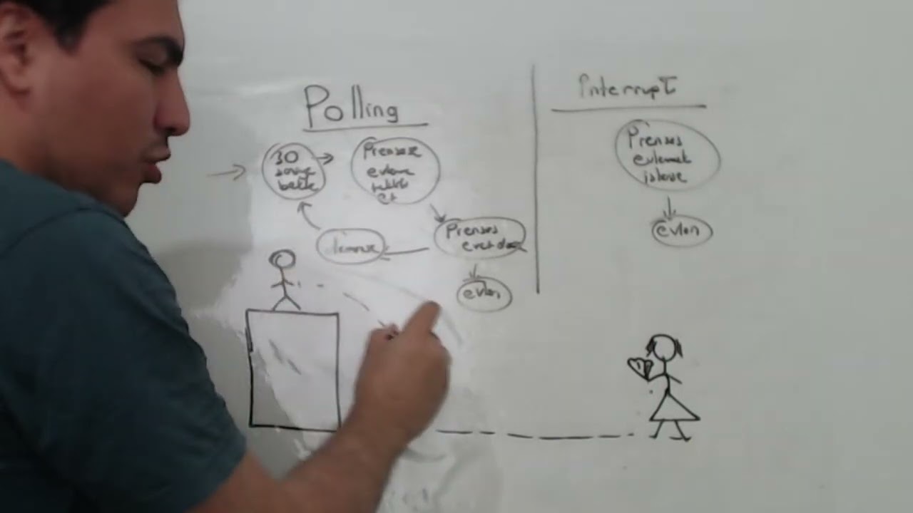
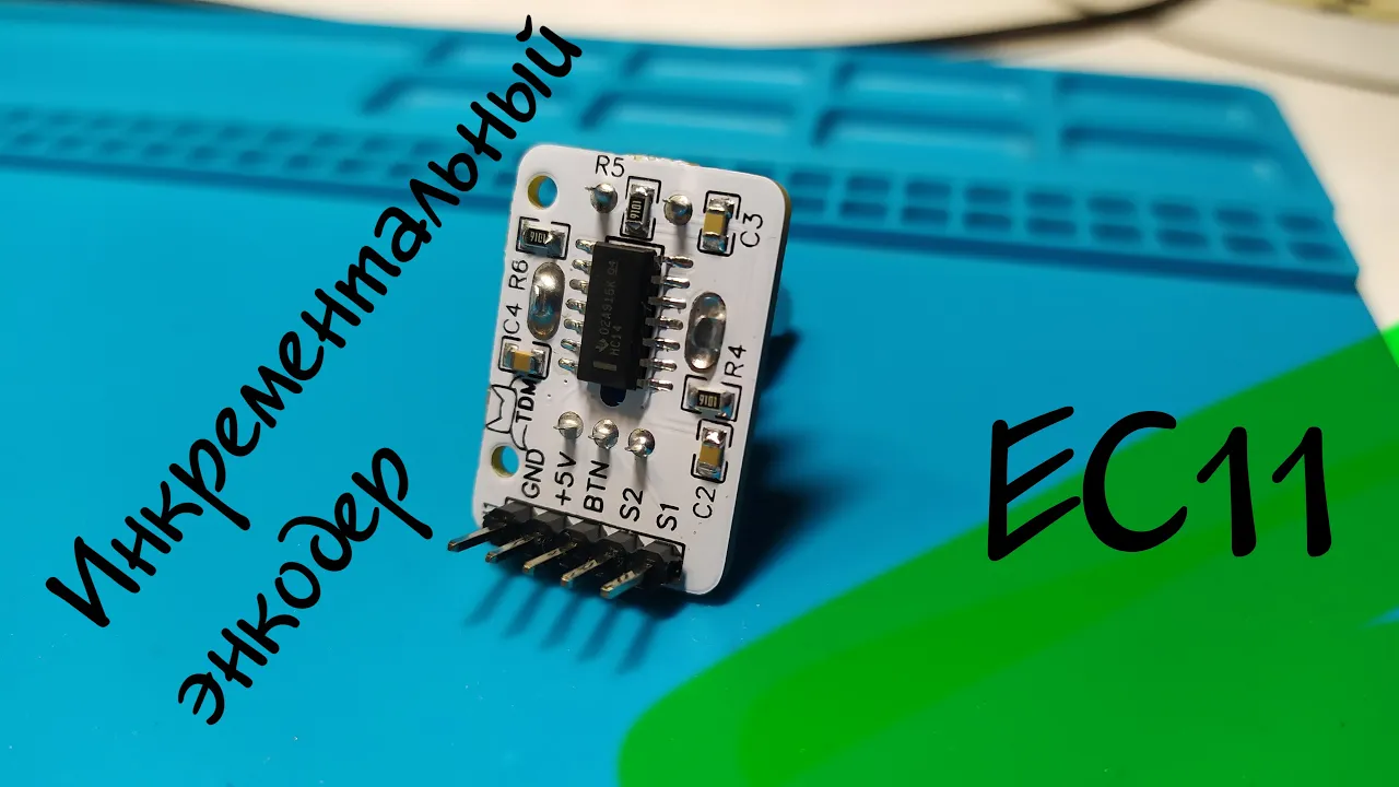
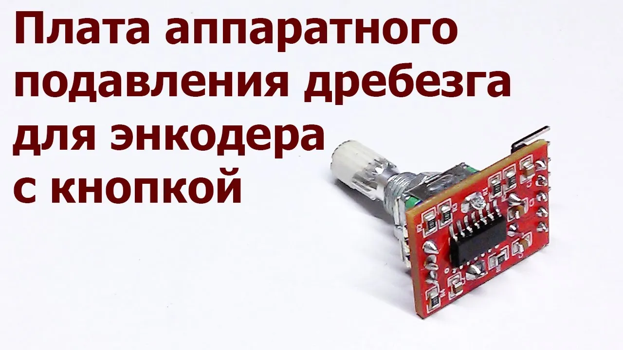
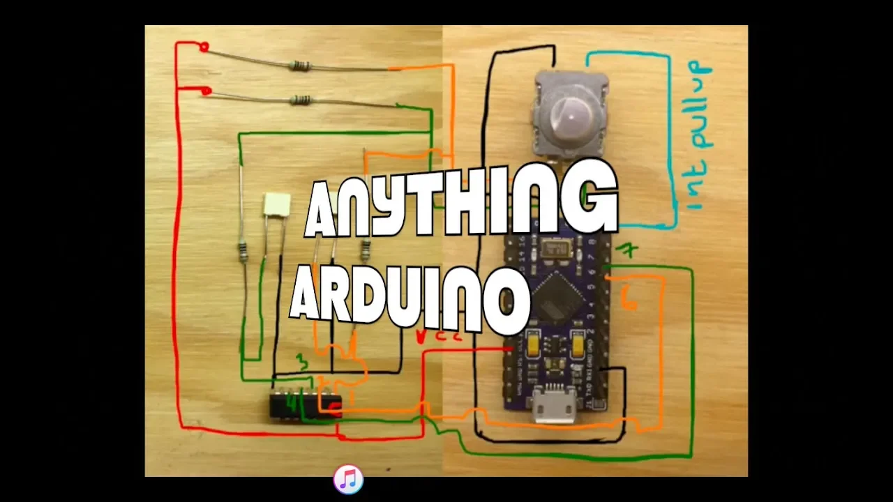
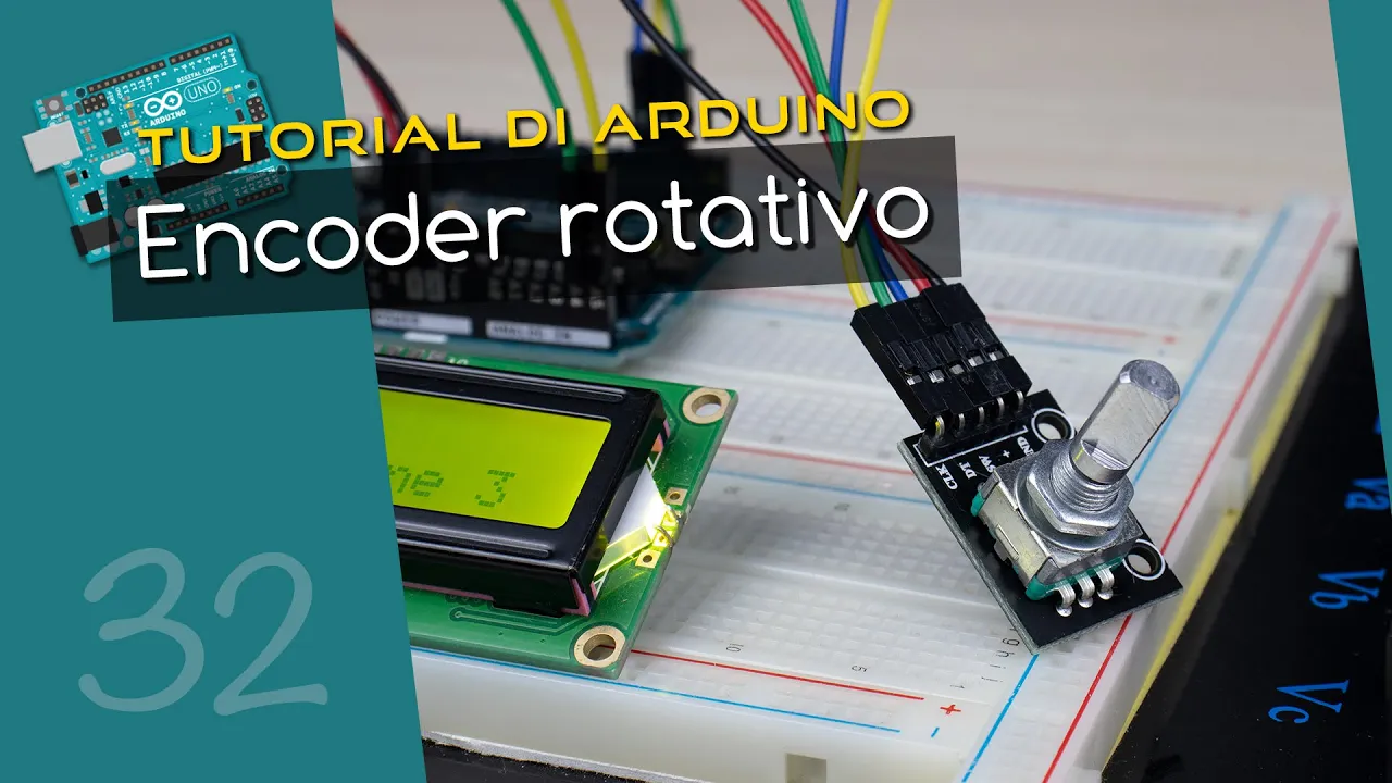
hi everyone many arduino projects require a form of input from the end user this is usually done with buttons that you connect to different input pins and based on what button is pressed you can respond to that press in the code in the usual arrangement we have buttons that trigger a menu and then other buttons that increase or decrease a value or change some of the project parameters however if we want to have a more interesting interface that is also flexible and simple to use we can use a rotary encoder to do all of the actions that way this video is partially sponsored by pcb way feel free to visit their website pcbway.com and get your pcb prototypes built and shipped out in just 24 hours for only five dollars not only that you can order pcbs but you can also have your project assembled by pcb way you can order smd stencils for your projects or create funny shaped projects with their flexible pcbs visit pcbway.com today and get your pcb prototypes a rotary encoder is generally a position sensor that can tell us the angular position of a rotating shaft there are two types of rotary encoders absolute and incremental with absolute rotary encoders you know the angle at which the encoder is at any given point in time as each position generates a different code to descend to the output incremental encoders on the other hand return the number of increments that the shaft has turned without knowing where it started and these are the ones that we'll focus on today a rotary encoder is very similar to a potentiometer with the main difference being that there is no start and stop positions they can rotate indefinitely and can offer a great output resolution telling us the change in position that happened since the turning started contrary to this potentiometers usually turn only three-quarters of a circle and are usually best suited for situations where we need to know the exact angle at which the potentiometer is inside the encoder there is a plate with contacts and two output terminals marked as clk and dt the plate is connected to the ground and both of the pins are pulled high through resistors when the plate turns it connects the output pins to the ground in a particular order generating signals that are shifted 90 degrees from each other depending on the direction that the encoder is turned to the order at which the pins are switched low is also reversed so we can identify the direction from that one of the pins on the encoder is called primary and is marked as clk this pin will go through the cycle of going high and back to low with each rotation click on the encoder depending on the direction of the rotation dt will be turned low before or after clk a rotary encoder module usually have five pins we have the usual vcc and ground where we connect the input voltage and then we have the clk and dt pins which are the output signals from the encoder very often a rotary encoder has a fifth pin that is connected to the ground through the built-in normally open switch this switch can be used as any other momentary switch and i have an entire video on switches if you want to take a look the encoder can basically be connected to any input pins on the arduino but there are a few caves that we need to be aware of for the method of reading it the encoder state can be read with the arduino in one of two ways either with pulling or with interrupts if we choose to read the encoder with pulling we need to read the value on the clk and it depends on each cycle of the code and depending on the complexity of the project the arduino might be busy doing some other work while the encoder is turned if that happens then we might miss the change of the encoder and not react to it at all since we were busy doing something else when the encoder was turned to mitigate this it is recommended that we connect the encoder using the interrupt pins on the arduino i've explained the interrupts in another video in great detail but basically when we use interrupts the arduino will stop its current execution and handle the reading of the rotary encoder instead on the arduino uno or nano we have two interrupts available for use on pins 2 and 3 and it is best if the encoder is connected to both of them however if the interrupt pins are required for some other inputs as well as the switch on the encoder for example we can only use one of them and connect dt to the interrupt pin this won't be ideal but it will be a lot better than just pulling the encoder state to program the arduino we will use a dedicated library called the encoder that i'll link in the description you can also install directly from the library manager on the arduino ide this library can work with multiple encoders at a time and depending on the capabilities of the use pins on the microcontroller it will either use interrupts or it will default to just pulling the input values at the beginning of the sketch we first include the library and we define the encoder object with the pins that we have the encoder connected to in my case i chose to use pens 3 and 4 where only pin 3 has interrupt capabilities i chose to use just one interrupt because i wanted to have pin 2 available with the second interrupt so i can also connect the switch of the encoder to it to do this in the setup function we first define pin 2 as an input using the internal pull up resistor to keep the pin high and we then use the attach interrupt function to set it so it executes the handle switch function on the rising edge of the signal this way the handle switch function will be called every time when we release the switch on the rotary encoder inside the loop function we first read the position of the rotary encoder and we compare this value with the value that we have for the previous position if the two are different we write the newly read value as the old position and display to the serial monitor when the encoder is turned there are hard stops or clicks that the shaft stops at in my case there are 30 such stops in a full circle but since the encoder will change the values of both the pins in one such click the value is incremented by 2 when read from the encoder to mitigate this and count every click once we can simply choose to update the new position value only at the even position and display the position divided by 2.
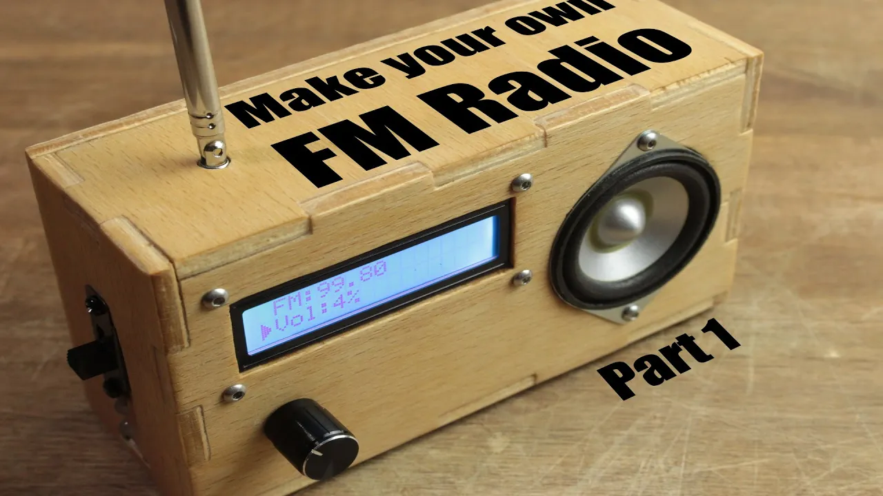
since we now know how to interface the encoder i went ahead and integrated this encoder with the other project that i'm working on where so far i have the ds-1302 real-time clock and the 20x4 lcd screen attached when the encoder is turned the updated position value is written to the lcd screen and i plan to use this later on so i can adjust different values in the final project if you are interested in seeing this then be sure to subscribe to the channel like and share this video with your friends and i'll see you all in the next one you
Up Next

9:27
Micromouse Construction Tutorial Part 3: Sensors & Testing
@MicroMouse
9.9K views•2009-08-27

12:54
Triumph of Orthodoxy Icon: Byzantine Art & History Explained
@BenCallan
2.1K views•2024-08-06

9:49
FastAPI vs Flask vs Django: Choosing the Right Python Web Framework
@TechWithTim
302.5K views•2024-05-26

1:42
Game of Thrones Opening Credits: A Cinematic Analysis
@gameofthrones
46.3M views•2011-04-18
Related Study Plans & Knowledge Roadmaps
Structured learning paths in General & Interdisciplinary Studies
general-studies
Elevator Engineering: History, Physics & Cities
01From Hoists to Safety Brakes: The Dawn of Vertical Lift
02Hydraulic vs. Traction: The Engineering Physics of Elevators
03Modern Speed, Safety, and Algorithms
+ 2 more learning modules
12h5 modules
Explore Roadmap
general-studies
Rubber: Material Science, History & Geopolitics
01Origins of Natural Rubber & Mesoamerican History
02The Chemistry of Natural Rubber & Vulcanization
03The Geopolitics of the Rubber Boom & Colonization
+ 2 more learning modules
12h5 modules
Explore Roadmap
general-studies
Containerization: Evolution, Logistics & Trade
01Ancient Trade & Bulk Cargo: Amphorae to Barrels
02The Industrial Revolution & Cardboard Packaging
03The Containerization Revolution: Malcom McLean
+ 2 more learning modules
12h5 modules
Explore Roadmap
general-studies
Textile Tech: Evolution, Labor & Global Impact
01Pre-Industrial Textiles: Handloom & Cottage Industry
02Mechanization: The Spinning Jenny to the Power Loom
03The Factory System & Global Labor Transformation
+ 2 more learning modules
10h5 modules
Explore Roadmap