










![Algoritmo Solución laberinto | Seguidor de pared | Wall follower [ RoboMind ]](https://i.ytimg.com/vi_webp/KoSYNSvj6ds/maxresdefault.webp)





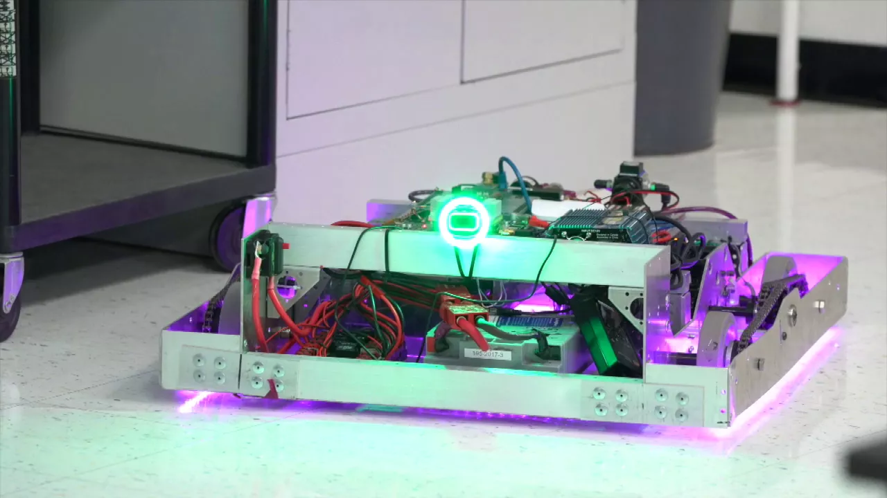


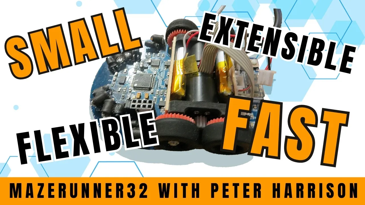


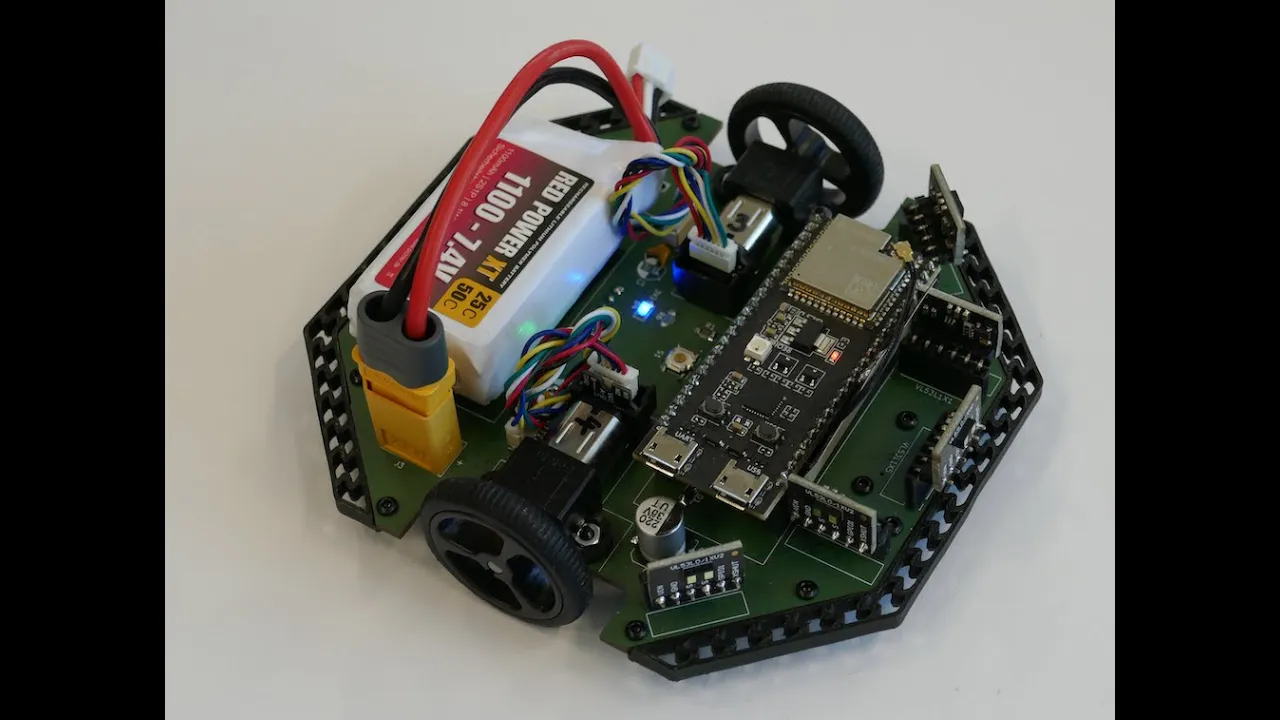
This tutorial demonstrates the process of calibrating infrared sensors and testing a micromouse maze solver, including adjusting sensor positions for optimal readings, loading test programs to verify motor and sensor functionality, and fine-tuning the maze solver algorithm to minimize decision pauses for competitive performance.
Micromouse Construction Tutorial Part 3: Sensors & Testing
Added:Basic understanding of microcontrollers, specifically the Picaxe platform, including how to upload code and interface with I/O pins.
Fundamentals of electronics, including circuit continuity, basic soldering, and how to safely power a mobile robot.
The physics of Infrared (IR) sensors, including how emitters and receivers detect obstacles and measure relative distance.
Basic programming structures such as loops, conditional statements, and variable assignment for reading sensor data.
Implementation of basic maze-solving algorithms, such as the Wall Follower (Left/Right hand rule) and Flood Fill.
Proportional-Integral-Derivative (PID) control loops to smoothly adjust motor speeds based on real-time sensor feedback for precise alignment.
Sensor calibration techniques and digital filtering methods to handle ambient light interference and improve sensor reliability.
Hardware optimization and transition to more powerful microcontrollers (e.g., STM32 or ESP32) to support higher processing speeds for competitive Micromouse events.
9.9K views39likes9:27Original Release: 2009-08-27
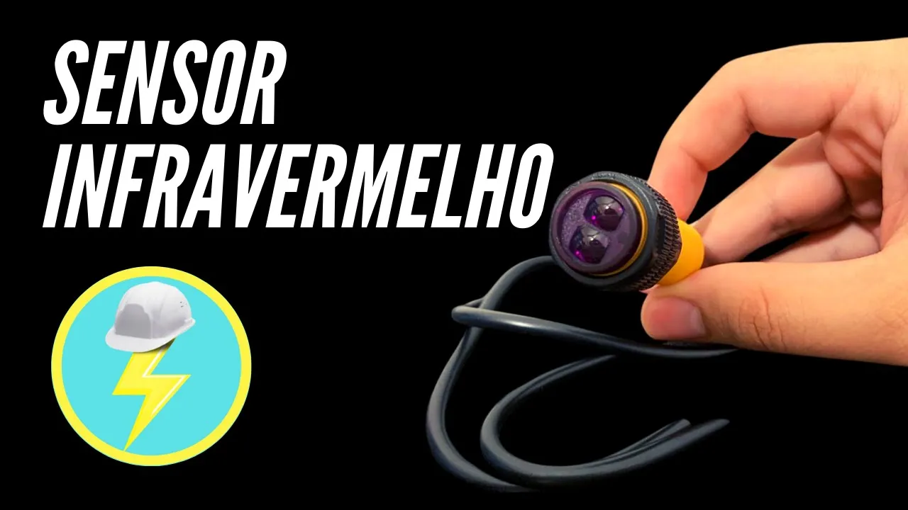
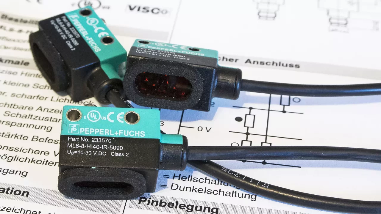
Okay, so now we're just leaving the infrared sensor LEDs. Short leg once again is the cathode. And the cathode goes where that straight line there is on the infrared on the LED signal.
So I think we'll probably bend going to bend that there.
Thread that in like that. Now, it's important not to have the LED past the edge of the PCB, otherwise if a wall comes up and hits it, it will nook the P the LED out of line. So, but I think that's about right. So, we'll solder that in there. I think we'll probably do about there.
Looks good. I'm going to bend like that actually.
Okay, just straighten that up. Should be a little hole there which you can locate. So, be a bit careful when you're pushing this in. Don't push it through your finger. Might need to use a pair of pliers just to pull that in. You could have the the mouse have that one just in just in like that. And we'll glue gun it in place. And then the back one. If you if you adjust the back one to push it in so that the mouse can just about rock. That back one needs to go in a little bit further. The mouse is pretty much finished. Now there's a few things that I have done is I've glue gunned the drawing pin on the front and the back just to make it more secure. I've got about half a millm space there just to give it a very very small rock.
Uh, I've slightly bent these capacitors over just to give myself a bit more room when I want to adjust the infrared sensors. I've added in the wire link, which I mentioned earlier, which will make your right hand sensor more accurate and it'll be less susceptible to noise. Uh, we got the peg in there now, which uh, holds the battery in place. And I think that's pretty much it. I just need to put the put the chips in. Now, these are the two driver chips, which will go at the back. And also, we've got the the 18X and the 28X, which obviously go at the front.
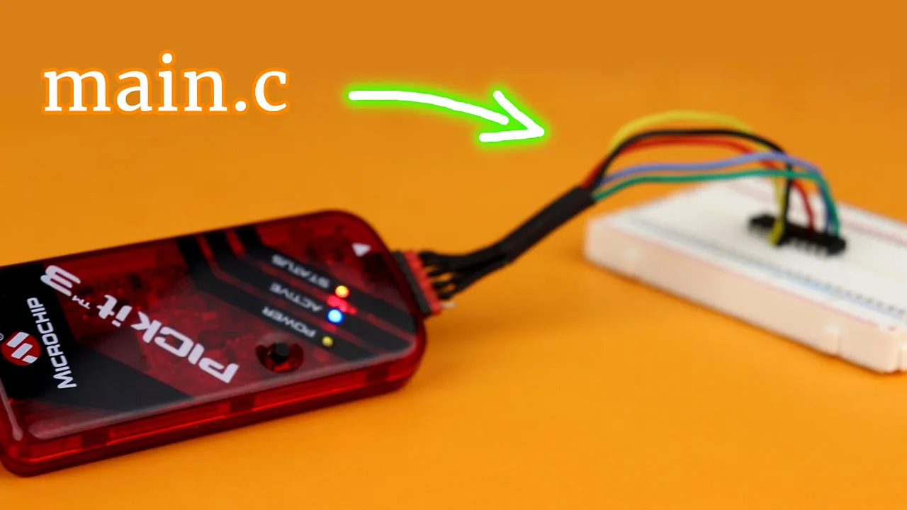
So, and that's it. And that'll be your completed mouse. Right, the mouse is completed and we've put the 9V battery on there. And what we're going to do now is to load up some simple test programs that come on the CD. So we'll get test one, which goes to the 28X1. We make sure we got it on the right chip. And we'll just make sure the right serial ports there.
Okay. So this is the the basic program for test one.
So, we'll switch the mouse on. Put that in there. Press F5. Okay, that's good. So, that shows that's communicating with the with the pickaxe. That's fine. You notice all three LEDs have come on. That's good.
And now we'll put the 18X program in which is going to be on the 18X. Okay.
Okay, that's in fine now. So, you should you should have now you should have the three LEDs on which are controlled by the 28X1 and the two LEDs which will be flashing will be on the 18X. Right. The first thing we're going to do is we're going to test the infrared sensors at the front and the infrared LEDs. This is done by pressing button A. Just press button A once. Those two LEDs go out.
Now if we press start once now you'll see that as I move my hand closer it will make the corresponding LED come on. So that okay now we press start button again and that's now that's now turning both the motors and what it's doing is it's actually testing that will counter there. So you can see the LEDs flashing on and off. Don't worry about the noise the noise the motors are making. We can put a small bit of oil on there which will quieten them down in a minute.
Press the start button again. That's now testing the other the other wheel counter there. That's so that seems to be working fine. Start again. Okay. So it's now testing the relay. You'll notice it's reversing the one wheel. Press again.
Because it's such a crude program, you have to you might have to press it a couple of times for it. But the 18X is controlling these two LEDs and the 28X is controlling that LED. And they're they're flashing using the communications between the two. Okay.
What I've got here is a tiny bit of oil.
I'm just going to put on the tip of this screwdriver. You don't want to put too much on, otherwise you'll um find that the encoder discs at the bottom will come off. Painted it with matte paint, blackboard paint, and I've put these little squares on so we can get the the walls lined up where we need them.
I've also added a little white dot to the front and the back in the very center of the mouse and drawn a pencil line down the center so it's easier to get the mouse lined up. We're now going to move on to the debug program. So, we'll load that up. We want the 28x1. That's correct.
You should be able to see these numbers increasing that represent what the infrared sensor can see. the reflective sensor. B1 is the front sensor. B2 is the right hand sensor and B 0 is the left hand sensor. So, as an object gets closer, you'll see these numbers increase. So, if I line the mouse up in the middle, I can make a note of the sensor readings. The right hand sensor is running at about 34 on the left hand wall at 7 cm. There again, PCB 7 cm away. And as we move the wall past, we'll get a reading. Sensor. Now, I've put a pencil mark at 8 1/2 cm. That's from this line here at 13 cm.
Once again, I've got a pencil line. And that gives me a reading so that the sensor readings both drop off at the same time when it reaches the edge of edge of a wall. Now, as I've got them in the right place, I'm now going to use a glue gun, and I'm just going to secure them permanently.
[Applause] Making sure not to get any glue on the lens. Right, that should secure the LEDs in now. So, if they do get nudged, they loaded the maze solver into the 18X. And I'm about to load the control program into the 28X1. But before I do this, I'm just going to change some of the default sensor settings to the ones that I noted earlier. But you should never expect your mouse to run perfectly first time.
So all I've done is I've put the program in with the numbers slightly altered, but we'll see how it runs. And that's not bad.
I think there is a bit of fine tuning you can do to the the angle of the turns and the short length before and after the turns. Here we go with a maze configuration with a few dead ends.
These are the pauses where the mouse is deciding what direction to go. Later on when we speed it up, we're going to try and get these pauses down to hardly anything at all.
And this is the point where you spend a lot of time making your mouse run perfectly. Okay, we've got the basic kit running pretty well now, but to make it more competitive, we're going to increase the power to the motors and we're going to increase the processing speed with some simple modifications.
Up Next
4:15
Micromouse Build: Soldering, Drivetrain & Encoders for Maze Solving
@Kenry
64.9K views•2021-01-04

12:54
Triumph of Orthodoxy Icon: Byzantine Art & History Explained
@BenCallan
2.1K views•2024-08-06

9:49
FastAPI vs Flask vs Django: Choosing the Right Python Web Framework
@TechWithTim
302.5K views•2024-05-26

1:42
Game of Thrones Opening Credits: A Cinematic Analysis
@gameofthrones
46.3M views•2011-04-18
Related Study Plans & Knowledge Roadmaps
Structured learning paths in General & Interdisciplinary Studies
general-studies
Elevator Engineering: History, Physics & Cities
01From Hoists to Safety Brakes: The Dawn of Vertical Lift
02Hydraulic vs. Traction: The Engineering Physics of Elevators
03Modern Speed, Safety, and Algorithms
+ 2 more learning modules
12h5 modules
Explore Roadmap
general-studies
Rubber: Material Science, History & Geopolitics
01Origins of Natural Rubber & Mesoamerican History
02The Chemistry of Natural Rubber & Vulcanization
03The Geopolitics of the Rubber Boom & Colonization
+ 2 more learning modules
12h5 modules
Explore Roadmap
general-studies
Containerization: Evolution, Logistics & Trade
01Ancient Trade & Bulk Cargo: Amphorae to Barrels
02The Industrial Revolution & Cardboard Packaging
03The Containerization Revolution: Malcom McLean
+ 2 more learning modules
12h5 modules
Explore Roadmap
general-studies
Textile Tech: Evolution, Labor & Global Impact
01Pre-Industrial Textiles: Handloom & Cottage Industry
02Mechanization: The Spinning Jenny to the Power Loom
03The Factory System & Global Labor Transformation
+ 2 more learning modules
10h5 modules
Explore Roadmap