









![Quadrature Mixers, IQ Demodulation, and the Tayloe Detector [devttys0 reupload]](https://i.ytimg.com/vi/gR46mGrfmOs/maxresdefault.jpg)






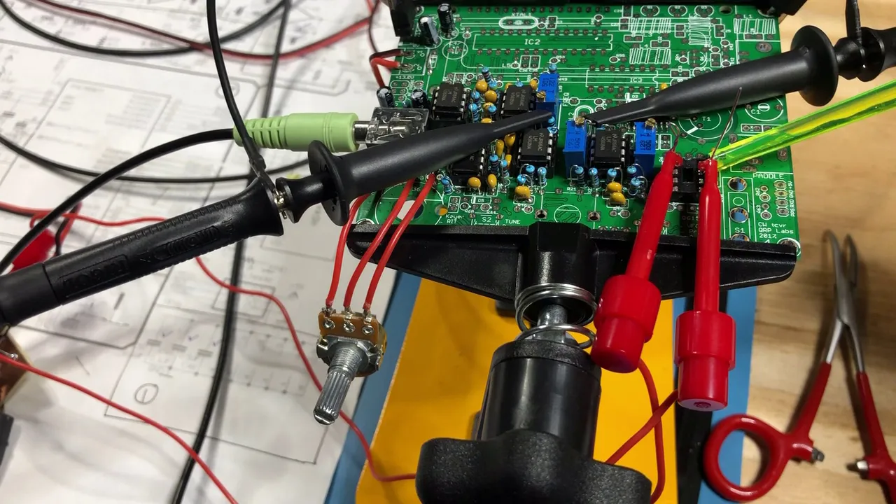


A quadrature phase oscillator can be constructed using a D flip-flop (SN74HC74) to divide a clock signal by four, generating two signals with a 90-degree phase shift; this approach maintains constant amplitude across frequencies unlike direct VCO outputs, making it suitable for driving NE612 mixers in SDR applications.
Homebrew SDR SSB Rig Part 2: Quadrature Phase Oscillator
Added:Fundamental understanding of Single Sideband (SSB) modulation and Software Defined Radio (SDR) architectures.
The concept of I/Q (In-phase and Quadrature) signals and why a 90-degree phase shift is required for image rejection in mixers.
Basic operation of digital logic gates, specifically D-type flip-flops (such as the SN74HC74) used for frequency division and phase generation.
Familiarity with programmable clock generators, specifically the Si5351, and how to control them via microcontrollers (e.g., Arduino using I2C).
Integrating the quadrature local oscillator (LO) with a switching mixer, such as a Tayloe Detector or double-balanced mixer, for frequency conversion.
Designing and implementing low-pass or band-pass filters to suppress unwanted harmonics generated by the square-wave output of the SN74HC74.
Interfacing the physical I/Q analog hardware with an ADC or PC soundcard and configuring SDR demodulation software (e.g., GNU Radio, HDSDR).
Analyzing and compensating for amplitude and phase imbalances in the I/Q paths to maximize sideband suppression in the transceiver.
7K views110likes19:54Original Release: 2018-03-21
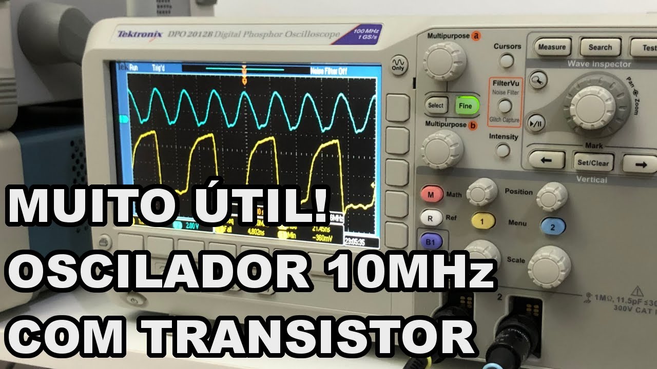
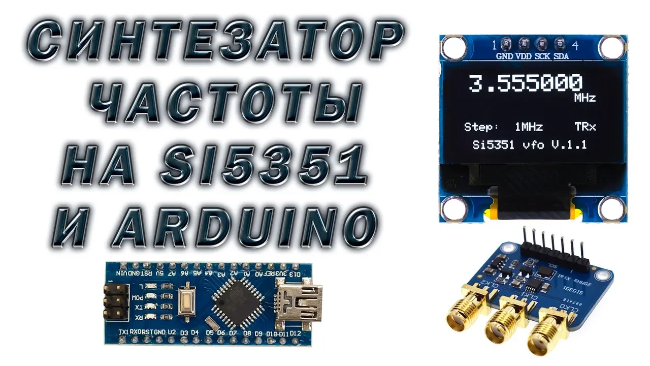
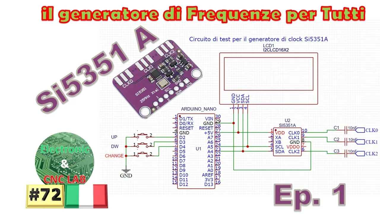
good afternoon everyone just thought I'd do a video today looking at the first part of the build which is the quadrature oscillator generator this particular circuit there's nothing special here you will see the circuit mentioned many times on the Internet so just to recap what we're trying to generate up front is some quadrature clock or quadrature oscillator signals that we can feed into our in e61 2's to produce the audio out which will then feed into our 10 seed so what we did as we outlined in the earlier video because we've now hooked up the the teensy microcontroller we've hooked it up to the the screen and we'll look at the circuit diagram and a sick we've also connected the rotary encoder and we have connected over here the SI 53:51 and clock zero is going through to our SN 74 HC 74 which is that Joule D flip-flop chip and like I say you know in a sec we have a look at the circuit diagram so the whole idea of the circuit here is for the at the moment the way it's configured is for the teensy to drive the SI 5351 and to multiply our selected frequency by 4 this was coming out the green coax here it goes into our jewel D flip-flop counter or flip-flop device which then outputs two quadrature outputs at one-quarter what's coming out of here so in other words we've got the frequency D and here is selected to 3.7 megahertz has been multiplied by four it clocks the two D flip-flops and then coming out is our output at 3.7 megahertz because this effectively does as does a divided by four and we can see that up here up on the scope so just recapping so we have two probes here this probe here is probing the input or the clock signal that's going into the D flip-flops coming out of our si 5351 and then the other channel is looking at one of the two outputs and there's obviously up here on the screen so the top trace is the output which is at in this particular case three point seven megahertz and we can see the clock coming out of the SI 5351 sitting at four times our design frequency you can see that when we move it up if we were just sort of go there roughly you can see one two three four four per output so does they indeed a divided by four and if we were now to move that let probe to the other output knob says it come on we can see the mirror so we're now looking at the two outputs of the quadrature and you can see there that ninety degrees phase shift so just sort of stick them off a little bit and then vary the frequency you can see those cities soon there nicely that can sink and the good thing too is I we were to look at the amplitude one of the disadvantages of the ESI 5351 at higher frequencies is that the output tends to drop off an amplitude whereas in this particular case because it's a logic device it just it just keeps the same amplitude all the way through so I'm now setting up the eret fourteen and out twenty four so right now that twenty seven effect I'll come down at the little Ostia so it's twenty-seven megahertz so that's twenty seven megahertz indicated on the display so the output psi 53:51 is actually four times that but that's that's that's fine so what else is of interest to look at that so yes the one that we talked at an earlier video and some of the comments about generating those two quadrature signals directly from the SI 5351 say what if we wish to use a notional o'clock zero and o'clock one there is still a winter project but as you can see what are the disadvantages we would have for that approach is for the high frequencies we would have a drop-off in the amplitude coming out of the SI 5351 so indeed we would have to have a couple of amplifiers one for each channel basically keeping the output amplitude constant and why I say that is because the next part of this project will have to now feed the output of this does generator here this oscillator or clocked you know to what you want to call it until we are in e61 to s now the in e61 two needs to see between 200 and 300 millivolts peak to peak so the good thing with this particular set up because we have a constant amplitude output across the frequency range I can just get away with using a couple of simple in this particular case I mean here's a couple of 20k trimpots this is junk box once I want something in the K range and I can set that on the output and then just trim to get the desired under load 200 to 300 millivolts peak to peak since one of the advantages of actually sticking with this particular circuit here is I don't have to worry about the reduction and amplitude of the SI 5351 at the higher frequencies so I'm just coming back to the circuit diagram and then after which we have a look at the code so like I say this is a very standard circuit there's nothing nothing special here this box here is the notional either the teensy and the rotary encoder the LCD screen in the SI 5351 what I've elected to do now and you can sort of just see it down here the the square board at the bottom is the audio board and then that has a series has quite a few pens that it requires to interface with the actual 10c itself this is a 3.5 and there are a number of spear pins that stick well beyond their board or in other words and not used by the board and I've tapped into some of those so we don't have any interference with the communications going on with the audio board so for the rotary encoder if you recall a couple of videos back that's got five pins coming out of it on the three pin side syndra's earth and the two outputs go to 35 and 36 now if if you were to wire this up and the frequency was going opposite to what you expected then just flip those two wires around or in the software flip around the penis' lineman's flipping the pen assignments and software is certainly easier and on the other side which is the switch side of the encoder one side is earth and the other side is going to pen dirty nine of the ten seat the SDA output for zero there's got a couple of SDA channels on the teensy so SDA zero is on pin 18 and SCL 0 is on 19 so here we have those the LCD screen interface with 18 and 19 and then in parallel effect as the SI 5351 and each of those devices also require and earth and 5 volts you see out here the output of the SI 53 clock to 0 which does this one here is now going down and as using as the clock signal and putting into these 2 d flip-flops just a simple voltage divider bias here just setting up the clock to be at zero with two 10k ohm resistors sitting between 5 volts and 0 and this is just a really nice way of getting a nice clean clocking signal output in from the TSI 53:51 not indicated there that's 100 nano farad's and then that clocks our 2d flip-flops and arranged in such a way that the output produces our quadrature outputs again 3 at the moment just a couple of 100 nano farad capacitors the is in 74 Hz 74 is a 14 pin device so there are a few pins here which are not used in the circuit diagram here and that's gonna go down here so pens 1 14 and 13 are all tied to VCC I just haven't included them here for clarity pen 5mm and pen 8 and not used so that's that's effectively what we have to generate our quadrature oscillator or our quantitative clock and now the next step will be to look at interfacing that with our in d6 1 2 s which will be the next steps right so I'm going to pause here and we'll just bring up the software and we'll just have a look at the differences all the changes made to the software that was presented a couple of videos back to make it compatible with the with this particular arrangement in the end the TSE so let's hold on and we'll actually okay so let's take a look at some software here and firstly I again apologize for the quite slightly quiet audio I've got into Windows 10 I've gone into recording devices I've gone into the properties for the microphone I've got boost turn on to 30 DB and a hundred percent and for whatever reason I just can't seem to make this volume in your louder so I apologize for that so what we have here is essentially the same software as we presented in a couple of videos back just looking at the software required to to talk to enter control the SI 53:51 later on we will add to the software to include the additional functionality to actually do the Software Defined so we'll introduce the DSP filters and we'll do that later on so this is just the initial code and like I say as we go through the build we will add more functionality in so for those who haven't used the teensy with the IDE if you go to the pr JC website where the 10c comes from or you do a google search on teensy and the arduino ide the integrated development environment you'll find some links to allow you or to show you how to basically do the Eddin to the ide to allow you to talk to the arduino so then under tools and under boards you will then get the teensy range coming up coming up here so it's very straightforward and once you've got it it's a write so looking at software here I will try and remember what I talked about last time and only talk about the differences so the no real change here I've just notionally said that the highest frequency we can go to is 30 migs and starting at 1 Meg you will recall just in the circuit diagram the pen assignments so you can see here that a push pin on that rotary encoder we assigned to the digital pin 39 and the two rotary pins with 35 and 36 so those you need to make sure that that is updated with whatever pins you and Nick to use and then we basically initialize will instantiate the the two objects so here on this particular one I'm using the liquid crystal display so I've included the library to talk to that and in my particular screen here the address to talk to it was 3f octal sometimes you'll find it's it's octal 27 but when I started up it didn't work so I went to 3f and then hold up she came and there we are just enabling via the SI 5351 no real changes here basically to setting up the import pins using those to find integer constants up here and then turning on the pull-up resistors again assigning the to interrupt pins so I'm now going slightly fast here but it's just a repeat of the video we did a couple back turning on the screen and initializing the dds no changes to this part here and in fact you'll find from this point onwards except for the last line and there are no changes so the the main loop there is no changes so it's looking for a change in frequency and if there is a change it'll update the display and then send the frequency and it's also looking for to see if the push pin has changed there is actually one change that I have made to a Candice going over here because there's been no changes at all this is all the same all the same here through what happens when you rotate the rotary encoder so for more information go back a couple of videos but what I've elected to do here I tried to look at for the for the digit that I want to change the rotary encoder I was initially toying with the idea of inverting the color some rather making it in this particular case white on blue I'd make it a white box with a with a black number the particular screen doesn't support that so I reverted to something I did some time ago and that's to use the underline cursor so right here at the staff the update display I am turning on the actual cursor and if you go back in this particular video here back to where I'm showing the LCD screen you will see under the digit that's being changed a cursor as opposed to being a - or a - on the whole robe a lot and I did that to allow me to use that SiC and grow to display additional functionality and that may turn out as we go through this project to be for example the audio bandwidth of the filter will use at the end of the SDR radio it could be a memory mode for doing some kind of memory scanning or something like that so in order to free up that row I've gone to a subtly different way of actually showing what digit is being changed so again and this is what is happening here so depending on what the red X is set to in other words which digit on changing I then place that cursor under it and the end in the suitable position so here is in position six position so I gained seven six by 4 et cetera et cetera and I think I covered it in that last video talking about software these two if statements here one win that's greater than ten weeks I won numerous lower than team mix just to make things look nice and nice and even on the screen and the only difference we can see down here between or the other difference we can see in this software versus what was presented a couple of videos back as we now want to multiply our frequency by for because it is mentioned before that D flip-flop is your D flip-flops they're in the process of creating or generating the quadrature signals divides the clock that have been clocked it by four so in order to make sure that we actually get the right frequency coming out and the frequency matching what we wanted which is this one here we need to multiply that by four so that's the only really thing you to do nothing special up here in terms of multiplying and dividing things by four just do the very end and it's nice and simple so that's a very brief and quick rundown on the software like I say we are going to add to this we're going to add additional functions so you basically do our phasing technique to demodulate that audio also going to do I go to play around with having the audio coming into the teensy board at 10 kilohertz which is roughly half of the bandwidth on the analog to digital converter its sampling at forty four kilohertz so that's are getting tweet Oracle so that's what we're going to do is I'm going to play with anyway so what we'll have to do then and we'll cover that certainly in a future video is then using heterodyne we'll bring that down in software down to DC and go from there so that's the annual difference but like I say we'll cover that in depth at a later in a later video so I'm going to leave that there now many questions please sing out but if you look at that video and we did a couple a couple of videos back on software you'll certainly see where the differences are and it's pretty minor just making sure that the particular screen we're using right now is the right one we've got the right pen assignments for the rotary and like I say we've got at the very end our frequency being multiplied by four as well as a subtle change to the way in which the purse is being displayed okay and Athiya which everybody 73's and we will continue on for this particular project chisel
Up Next
8:10
Using Rotary Encoders with Arduino: Interrupts and Code
@TasteTheCode
6.4K views•2021-05-09

12:54
Triumph of Orthodoxy Icon: Byzantine Art & History Explained
@BenCallan
2.1K views•2024-08-06

9:49
FastAPI vs Flask vs Django: Choosing the Right Python Web Framework
@TechWithTim
302.5K views•2024-05-26

1:42
Game of Thrones Opening Credits: A Cinematic Analysis
@gameofthrones
46.3M views•2011-04-18
Related Study Plans & Knowledge Roadmaps
Structured learning paths in General & Interdisciplinary Studies
general-studies
Elevator Engineering: History, Physics & Cities
01From Hoists to Safety Brakes: The Dawn of Vertical Lift
02Hydraulic vs. Traction: The Engineering Physics of Elevators
03Modern Speed, Safety, and Algorithms
+ 2 more learning modules
12h5 modules
Explore Roadmap
general-studies
Rubber: Material Science, History & Geopolitics
01Origins of Natural Rubber & Mesoamerican History
02The Chemistry of Natural Rubber & Vulcanization
03The Geopolitics of the Rubber Boom & Colonization
+ 2 more learning modules
12h5 modules
Explore Roadmap
general-studies
Containerization: Evolution, Logistics & Trade
01Ancient Trade & Bulk Cargo: Amphorae to Barrels
02The Industrial Revolution & Cardboard Packaging
03The Containerization Revolution: Malcom McLean
+ 2 more learning modules
12h5 modules
Explore Roadmap
general-studies
Textile Tech: Evolution, Labor & Global Impact
01Pre-Industrial Textiles: Handloom & Cottage Industry
02Mechanization: The Spinning Jenny to the Power Loom
03The Factory System & Global Labor Transformation
+ 2 more learning modules
10h5 modules
Explore Roadmap