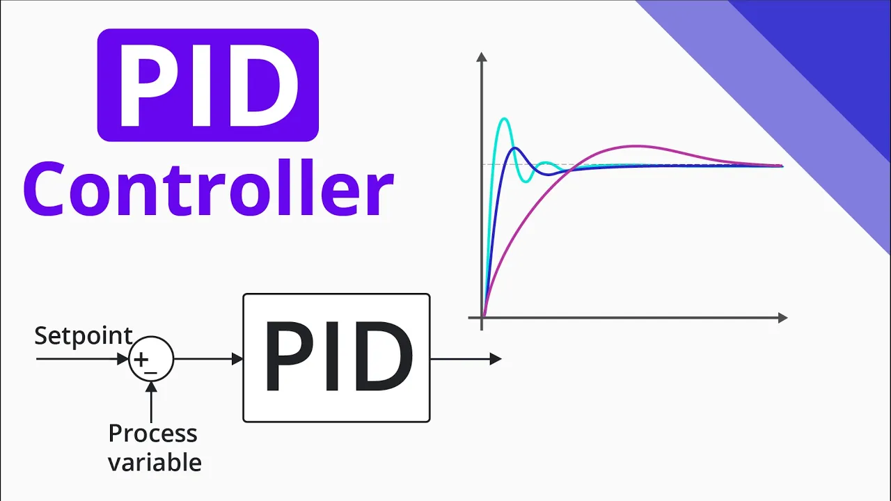
















This video demonstrates how to design a PD controller for micromouse robots by first characterizing the DC motor drive system as a first-order system with gain (km) and time constant (τm), then deriving appropriate PD controller parameters (KP and KD) from desired performance specifications such as damping ratio (ζ) and settling time (TD), rather than relying on trial-and-error tuning. The method involves measuring the motor's step response to determine km and τm, then using these values in mathematical expressions to calculate KP and KD that achieve specific control characteristics like minimal overshoot and fast settling time, which can then be further refined with feed-forward control for improved performance.
Encoder-Based PD Controller Design for Micromouse Robots
Added:Fundamental understanding of closed-loop feedback systems and PID (Proportional-Integral-Derivative) control concepts.
Basic knowledge of rotary encoders, including how they measure wheel position, speed, and direction.
Familiarity with the mechanical and electrical dynamics of differential-drive robots, such as DC motor characteristics and inertia.
Introductory engineering mathematics, specifically transfer functions, natural frequency, and damping ratios in second-order systems.
Implementation of discrete-time PD control algorithms on a microcontroller (e.g., STM32 or Arduino) using timer interrupts.
Motion profiling and trajectory generation techniques (such as trapezoidal or S-curve velocity profiles) for smooth acceleration and deceleration.
Introduction of feedforward control to compensate for friction and physical system latency, working alongside the PD controller.
Integration of the low-level motor controller with high-level maze-solving algorithms (e.g., Flood Fill) for autonomous navigation.
6.7K views174likes1:13:33Original Release: 2022-12-06
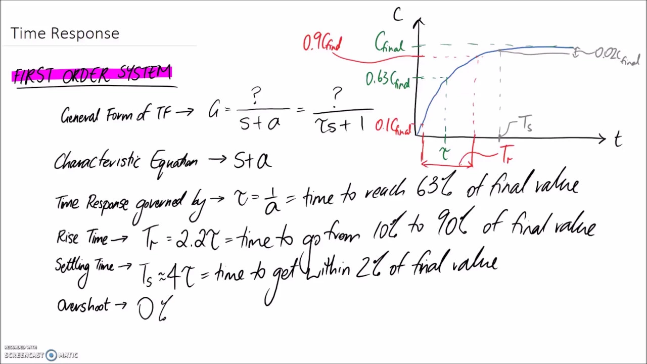
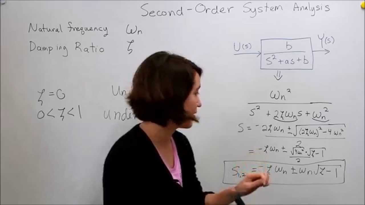
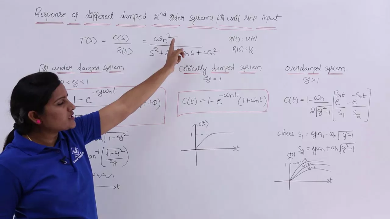
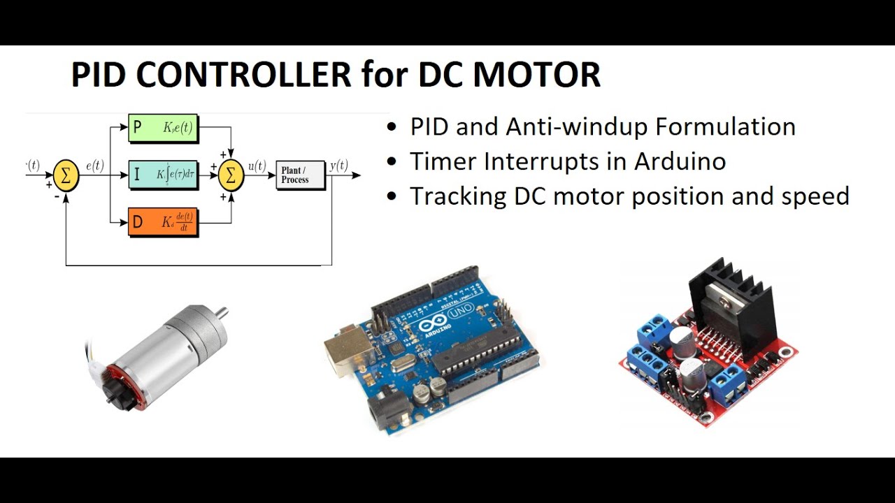
the name of the game is controlling your robot let me just find My Notes screen there we go so um we had a look before at using feed forward to try and improve less than Stellar controllers which to my mind immediately begged the question what constitutes a less than Stellar controller but which is also adequate for the job at hand and there are there's no end of possible control schemes available to you to control your robot and even when you've decided how you want to do this you have to uh and gone into the whole business of exactly what it is you're going to control and how it's going to be controlled and all the other things um inevitably uh you come up against the question of how do you tune your controller and tuning is is the term people use which um it's not a great term but it's it's what people say right it implies it's like a you know musical instrument where it's all set up and you just have to get it all tweaked just right and today um what I want to have a look at is first of all we'll go over a little bit about the characteristics of the system and the responses um just a bit of a refresher have a look at how we're going to implement some kind of closed loop control and and what kind of benefits you can expect to get from it we're going to have a look at how you tune or how you might try and set up that controller to give you a specific um set of outcomes and then we're going to have a look at how you can eliminate hopefully all of that that tedious and potentially dangerous tuning activity and replace it with some relatively simple calculations that shouldn't let you get right on with the job and make what um I have variously called a quick and dirty controller or a just good enough controller think of it like just in time delivery but for controllers so the first step is to characterize the drive system and we went through this once before but um we'll we'll just go through it again and note that the um we're going to be using DC motors to drive a wheeled mobile Road World mobile robot and for the sake of simplification we'll use a unicycle type model where we're just talking about a motor a wheel and you're going to move it at varying speeds and to position your robot where you want it to go and we have to note something about this drivetrain or a few things about this drivetrain first of all the applied voltage determines the speed at which the motor will go if we wish to accelerate the motor and that's the robot we need to apply some current if the load changes we need to change the current if we want to keep the speed constantly it's all this interaction going on one way or another though the motor drive system is a simple first order system and if you've done anything in electronics you'll be familiar with first order systems these are for example the charge and discharge rate of capacitors they follow a very basic um exponential rule um and there are two constants which Define these first order systems one is the overall gain so if you put one volt in how many millimeters per second do you get out of it or uh how many Reds per minute or whatever it is your unit might be and the other is the system time constant which is how long it takes um to to get to some fraction of the of the final value these are very very common kinds of systems all sorts of things follow these rules and if you want if you're not happy with the robot thing or if you're not happy with the capacitors something which is more intuitive perhaps is maybe applying currents to a heating element for a soldering iron or a hot plate or you're a cooker or something like that okay so you might start off by applying a step change um in the current to the heater or to the voltage to a motor at time zero and you can see that as the blue line on here and then over time the output the temperature the speed whatever it is that you're measuring will climb slowly towards some final value now I've shown the blue line as going up to the same to the final value but of course you know you might put in one volt and get out of it 240 revs per minute or something like that so this is this is merely uh showing what the expected step response is foreign so we see the gain which we'll refer to again and again today as as km and we'll see the time constant TM the time constant is defined here as the time taken for the output to reach 63 percent of its final steady state value 63 give or take it's it's 1 minus E to the minus one um and A good rule of thumb is that it will take four time constants to get to about 95 of the final value and five time constants to get to about 99 of the final value but within 19 within five percent of the final value in four time constants all right so we can do an experiment and we can apply voltages um to a motor oh no uh let's try that again sorry um I can't see what's going on on the zoom calls so I don't know what's right um and what we get is a series of outputs so here I have an experimental setup I've applied a a number of fixed voltages between one and six volts to a motor and I have measured the speed of the output I have incorrectly shown the units as millimeters per second but you'll see in a moment it's actually degrees per second and it should be apparent that in all cases the output reaches some final steady state value after a certain amount of time and the spacing between those lines looks to be fairly even which implies that there is a linear relationship between the applied voltage and the final steady state value not very clearly shown on here is a curve calculated in the spreadsheet and drawn underneath the experimental values and that curve is the is described by the exponential equation on the right there so this is my model the solid curve which you can't see is the model of the motor and the somewhat scratchy lines are the experimental data and the point perhaps is just to show that the real data coming from a real system is a very very good fit for this model and so my model is a valid description of the system and it is determined by just two constants um the time constant we could work out by just having a look at the steady state value here and go and find out where it the data gets to around about 60 percent of that to find the game um the easiest thing to do is to Simply take those final steady state values plot them on a graph join them up and get the slope of that line and that will give us our km and for this particular model km the game turns out to be 2064.7 um he says with optimistic Precision um degrees per second per vault um we'll just for later purposes we'll just remind ourselves that this line does not go through zero because um mechanical constraints mean that you need a little bit of voltage just to get things moving Let's do an experiment um and I'll switch over to the experiment which I hope you can all see and what we have here is in the top right a picture of a motor system I'll just move the camera around what it is in fact is a standard UK Mars bot I've disconnected the onboard Motors and connected them to getting my own lights here connected them up to another mode so same kind and I've connected that motor to a large wheel and the wheel um has some weights in it and I've set it up so that it has approximately the same inertia as the robot itself so that is to say it represents a similar load to the robot so the results you see you see should be um reasonably comparable to those that you would get from running the robot itself so one of the things that we can do I have an app which I've written which talks to the robot and we'll just um cool add up one way screen so I can I'll just reset everything [Music] I can do the system identification here I'm only doing one voltage I'm going to apply three volts to the motor and have it spin up um until it reaches steady state and then I can examine the response and just verify that I've actually got um something sensible um going on here and if I zoom in you can see that the final steady state is somewhere around 5800 degrees per second and um 63 of that is about 3 600 and we cross 3600 in a little over 300 milliseconds right so I have a game um of just over two thousand it's actually slightly under when you calculate it this way but but recall you need a series to get the game properly uh and I have a time constant of 0.325 milliseconds uh 0.325 seconds and these numbers you can see down here the robot has those stored in them this code the basic code by the way is just UK miles Block Maze Runner code it's it's the same stuff but with just an adaptation to let me talk to it over the PC um so we'll just set that back now we saw in a previous talk that once you have these constants you can try to drive the motor knowing something about how it should respond so I have set up on here the speed feed forward which you calculate from the gain the acceleration feed forward and the that bias value right the amount of voltage that's needed to just make it move at all we'll just send that off to the robot to be sure that it's there and we're going to run a profile using only open loop control feed forward control and you can see that I get my green line here is what the profile should look like it's supposed to be doing four rotations at up to 3 600 Degrees per second and the solid blue line is what it actually managed and it's it's had a fair old try right but it's not done too badly my calculations are reasonably good the upper graph shows in Orange what's actually being sent to the motor underneath that hidden because it's the same thing is the feet forward drive voltage and shown here dotted because it the controller is not active is the voltage coming from the control that we're going to describe later so this is the basic kind of lab setup I'm not going to run this any number of times and get slightly different results and if you have a look I've got a little pointer on here so you can see when it's done the proper amount a thing to Bear In Mind by the way is that the um the drive system is um it's adequate for the job the robot was designed to do but in terms of global quality uh it leaves a little to be desired right so you've got a 12 count per Revolution encoder you've got a 22 on gearbox in it that means that the very the absolute resolution that can be achieved is only about three degrees so you can expect just one count to move the motor the output rotor this much right I'm not pointing this out just so that I can show off later and if we run it well it's not terrific but you know it's not bad seem worse if I reduce the drive voltage well which I've done my power supply it's currently at seven volts so I'm going to turn it down to just 5 volts and run it again [Music] it still works because remember inside the Maze Runner code we compensate for the supply voltage so if it asks for five volts it gets five volts so it says five volts available it's a point worth bearing in mind for later turn that back up because this is open loop it has it's not good at dealing with problems we can deal with the the supply voltage by compensating for what we measure from the battery but if I apply a scientifically calibrated load with a cotton bug um and run it again you can guess what's going to happen right [Music] it never gets up to speed it's friction this is just like having a robot Drive uphill or has happened to me once just before a competition to get a long hair wrapped around the drive axle and things don't go well so this this it's not good at compensating for disturbances or changes in the load or any of those kinds of things foreign [Music] in order to get full control of the system we need some kind of closed loop feedback system and here um I'm going to be implementing a PD controller you've come across PID controllers for reasons that we can discuss at another on another occasion over a bit you don't need the item for this particular kind of controller so we just deal with PD in general um if you just if you don't have to have a long-term zero error and if you're using something like position piggy is adequate if you do have to eliminate long-term errors and offsets or if you're dealing with a speed control which this isn't I know it looks like it but it isn't and a pi controller was that you can leave the item right but for our purposes we only need the PD terms so we can draw a little block diagram and we can have the system itself which we know something about and some magical bit of software or Electronics which will have a look at the error between the difference between what we want the output to be the set point and what it actually is the output YT and it will have a look at that error and it will generate a signal based upon that error to try and drive the system to the right place and the benefits that you get from this are you can compensate for uh systematic errors so if I design a system um and set it up right and you go and you implement it on um your robot but your robot's got a slightly different you know motor characteristic or whatever I don't want yours to behave horribly differently just because your motor is slightly different or your wheels are slightly out or whatever so I want to try and get rid of those kinds of things I also want to be able to remove the effect of disturbances um so you know if I driving uphill or downhill I don't really want it to suddenly go slower or not go as far as it should do or or have any of these other kinds of upsets and also think back a moments to the first order response right so this has got a time constant of 0.325 seconds and if I just apply the voltage and allowed the thing to wind itself up to speed on its own using that kind of response it would take four time constants to get to within five percent of the set point well that's 1.2 seconds I was watching videos of the um recent student micromouse contest in Japan the other day and there half size mice on 16 by 16 maze we're running the whole damn course in two seconds you can't be waiting 1.2 seconds for it to Just Wind itself up to speed and decide what to do you need better performance so we can write um equations which describe the system these are transfer functions um I have no idea how many of you are familiar with transfer functions wave a hand if you understand anything at all about transfer functions in the estimate right okay so um it's magic that's the most important thing to remember there is Magic which lets you describe Dynamic systems in terms of complex numbers the square root of -1 and frequencies and and other such nonsense and better people than you and I have worked out how to use these things uh allowing you to mostly um plug in the answers but here in these transfer functions s is a function of frequency and you can think of it as a time delay as also it depends on your perspective so the PD controller has two constants KP and KD right these determine its Behavior they determine everything about it system itself already has two constants that we've seen before km is the gain and TM is the rise time the the time constant of the first order response now through the magic of mathematics we can write down an expression which describes the output in terms of the set point and the error and that looks like that I expect you're thrilled um so uh for those of you who don't have uh a background in these things this looks like you've already hit an insurmountable obstacle and you're ready to give up so what do you do well it turns out that these kinds of systems where you're feeding back um a first order system and an integrator which is what how we get the distance out of the the speed are generically called second order systems and these are very well understood at least in the control theory domain they're very well understood you and I may not have a thorough understanding of them but you know there are techniques and there's no end of literature in fact if you go and pick up any book on Control Systems I pretty much guarantee that three-quarters of it is going to be about handling second order systems because even when you have much more complicated systems people love to try and simplify them down into second order systems so that they can use these well-established techniques if they fail then by all means make life more difficult for yourself but if you can make it work with just a second order standard system life is good now these systems have two defining characteristics one is the damping ratio Zeta written with this annoying annoyingly hard to write Greek letter uh and the other is the natural frequency you can think of the natural frequency as being like the bandwidth of the system and you can think of it as determining the rise time right the time it takes to get from zero up to some particular set point and these um these values appear in this equation and we'll see how in a moment they're not there right but we'll see where they come from in a moment so if second order systems are well understood um what how do they respond right we've had a look at first order systems and they're they seem pretty straightforward right sluggish but straightforward second order system is somewhat more complicated if we take a normalized generic second order system and a player step input to it you can get all sorts of different outputs and the values of the damping ratio Zeta and the bandwidth Omega will affect that so here I've plotted changes only in the damping ratio they have the same this is a normalized system it's not a real system so the the bandwidth is the same but I've changed the damping ratio and you can see that for small values of the damping ratio you get an oscillatory response which dies away and that inevitably means that there will be some overshoot for large values you can see that you get a more gradual climb up to the steady state and it's important to note that you always do get this steady state right the systems that we're talking about this will always Converge on some steady state there are some interesting values of note for Zeta which are always good to kind of keep in the back of your mind one is uh Zeta equals one this is so-called critical damping and it's the value the largest value sorry the smallest value which means there is no overshoot and a value of 0.7 well 0.707 um more accurately is another interesting value it's the value which um perhaps most quickly gets you to within five percent of your target right that's five percent we were talking about before it's also numerically convenient because it's um a half the square root of two and that that makes some calculations easier a bit later so that's if we change the damping ratio what if we keep the damping ratio the same but change the bandwidth the frequency of the whole thing um and what that does is change the settling time so these responses all have um uh a damping ratio of 0.5 but they've got different bandwidths and the system with the highest bandwidth the green one shoots up fastest and gets to within five percent quickest and the other will take considerably longer right so this is not quite why I'm trying to get you to understand anything deep about second order systems the purpose here is simply to show you that there are two key parameters that Define the behavior of the system the damping ratio on the bandwidth Unfortunately they interact so changing one tends to affect the other but don't worry not going to be a problem so step responses are all very well but they're not much use to us for a robots if you're designing a hot plate for doing some Reflow soldering terrific okay you can apply a voltage uh uh change the set point Sorry in your controller you can measure the temperature you can see the kinds of responses that we've got and you can plan to have a particular amount of overshoot or no overshoot and you can adjust the bandwidth to get the rise time and you can you can chart around until you get a nice response but that's not how we drive robots nobody in their right mind moves a robot from here to 200 millimeters Away by suddenly setting a new set point of 200 millimeters because well if you did and you wanted a fast response what are you going to do about the overstream you can't ever go shooting past where it's supposed to be and then oscillating back and forth until it's you know in the right place that will be daft similarly you don't really want to see your robot responding to um the loss of a wall right when it's following a wall you don't really want to see it flapping around whilst the response settles we don't do that what we do instead is we provide profiles that is Step changes small step changes in distance and those are how will drive the robot on a fixed speed so if we want to go 100 millimeters per second then every hundredth of a second we can move it on by just the one millimeter these are small amounts right so the important thing is although the responses are important to describe the system they're not a good way to test it plenty of people do I you know I know some some very well performing robots who actually test their controllers by simply setting the robot down and then just giving it a poke and seeing how it responds does it oscillate back and forth does it sort of sit and soak or does it just stay where you've poked it to I would suggest this is not the best way but what happens when you come to try and work out what are appropriate values for these control constants KP and KD if you you know just sort of sitting um poking some values and seeing what happens what if they're horribly wrong you don't really want your robot suddenly shooting Off the Bench or running into the cat or going up in smoke or destroying the gearbox right so you don't you can't just poke odd values in and see what happens so you you turn back to everybody's friend um Google or go or whatever is your your fancy or that control systems test book that you you had from many years ago and never read and you'll find out how to tune your controller and you will discover that there are some intense and scary mathematical techniques Available to You involving graphs the like of which you'd never see and there are some slightly more empirical methods um and we'll come across one of the one of the four methods that you're most likely to come across is a thing called singular nickels um where you you um make measurements of the performance of your system and then do some maths on those measurements and and derive some controller constants unfortunately they're not suitable for what we're doing um all of these techniques require skill and experience to apply well and quite often they require an intimate knowledge of what's going on under the hood inside the system right the behavior of it and how things can work and even worse as with so much you look up on the Internet it's domain specific right you want to solve problem a somebody else has solved a problem that looks like it but it's for domain B it's something different and you think well nevermind it sounds a bit right I can apply that and you can't okay it just doesn't work quite that simply unfortunately so what can you do with tuning well let's have a look let's go back to the controller I've lost right let's just reset everything and down here you can see I have a little box for KP and KD now hands up if you've ever looked up on the Internet how to tune a motor controller or a robot controller yeah of course you have and I'm willing to bet that one of the early things that you come across is something like well start off by setting the value of KP to one and see how it responds all right let's do that then shall we [Music] KP is one crazy is zero we're going to use no feed forward only the controller and we'll just just in case it comes back exactly where it's supposed to uh we'll set it up and see how we go anybody got any predictions um nothing because I forgot to write the new values in we'll try again [Music] well what can you make of that then it's actually not far off where it's supposed to be that's encouraging but I think we can agree that this is a less than ideal response okay first off the motor voltage um shut up and saturated at six volts which is the most it can have and then it immediately went back negative to -4 volts and then saturated again and then just it became a bang bang forward backwards controller in some desperate attempt to get control of the Soul system and then it pretty much failed son um what's the next thing they say you should do any suggestions I'll put KD in to try and pull it back oh without even attempting to change Kpop no no do divide divide your uh by 10 for a start divided by ten yeah I think you know what you see is is indicative of resistant with too much gain all right because the the error builds and it immediately runs out of steam this is another reason why doing step responses is not a clever way to do this um and this could in principle and shot your robot across the room not to mention the fact that suddenly switching between plus six and minus six volts isn't doing your drivetrain any good at all so remember to write the results out this time and we'll move it again oh we're just just in case [Music] well that's not so bad right I mean he's overshot um but the response looks like it might be having maybe the right kind of shape to it um not very impressed by the motor voltage that's being generated this dotted line by the way is what the feed forward controller thinks you should have to do for this profile and a good indication by the way that we've got a good controller is if the controller generates something very similar to what the feed forward controller does because the V forward controller knows what the voltages should be right so that's an improvement so what what do we do now do we move KP larger or smaller or leave it as it is horrible I thought a bit less all right Mark half Point uh what other way just a bit less write that out [Music] um it's hard to say if that's really an improvement in fact it's even harder to say if it's getting better let's carry on moving it down in the same kind of Step well I I've you know it's hard to say that this is an improvement right it's not saturating but it is getting way up to six volts so maybe it's still too big so let's make it properly small and see what happens then look at that it's not even clear that making this bigger or smaller is a definite Improvement right um so now having typically right you'd be sitting there with this new controller this new robot and your software and you bounce it around the room and you're thinking what do I do right nothing I do with changing KP seems to make any difference and why is absolutely certain is that none of this matches the experience that you see in all those helpful tutorials on the internet none of it so you think oh well maybe I'll just maybe I'll mess with KD right see if that makes a difference what are we going to do with KD how big should we make KD come on make me an offer uh 10 for the Katy Perry okay.001 write that out [Music] that's actually encouraging so maybe we'll make it bigger not that big maybe that big [Music] oh starting to approach the right shape now and look the motor Drive voltage is starting to look a little bit better let's just set this to my zero point increase it a bit more [Music] write it out and run it again this is very encouraging right I'm just gonna I'm gonna see if I can go too too far right because a good approach for these things when you're searching for a number is a binary search um so we'll just we'll double that write it out well by the way did you know it came back to the zero point um and [Music] now we're starting to get somewhere we're getting what might be an acceptable response and remember that from the previous talk that if you use feed forward as well then that can make up for a bad controller right so I'll add in I'll do full control and I'll use both feed forward and feedback and [Music] that's pretty good all right we'll just see how accurate it is that's not bad now the question is is it good enough would you stop here well if you don't stop here how do you know how far to go because imagine this wasn't a wheel stuck on the bench but this was your robot it sounds okay and you'll see what I mean by that in a moment it sounds okay and it gets to pretty close to where I want it to be and I could maybe excuse myself in having got some other constant slightly wrong and so this might be unacceptable accuracy and so you might think this is fine I could stop by that I mean my point is what are your criteria how do you know you've got a decent response or not well we won't answer that because that's partly subjective but let me just show you something interesting [Music] let's turn off the feed forward set the KB to the two and I'll set KD to be 1.1 and I think we can agree from our experiment that these are perhaps ridiculous numbers right but imagine now that you're you don't have the the application you don't have the Telemetry you have a robot set on the ground and you've put in these numbers from dabbling around at random and this is what you get all right now listen listen on the market this time right so I got a very nice looking response even the Telemetry looked good and it stopped cuck on where it's supposed to stop is this a good controller no not even slightly look at what's happened to the poor motor it's being bashed about well there's like this isn't going to live very long and you can hear it compared to what it was before you can hear that this is not a happy system but if this was your robot on the ground and you were following some naive tutorial on YouTube you go that's it I've cracked it right the robot does the right speed it ends up in the right place job done move on but I'm suggesting to you that you're just inviting a disaster down the road right so point is [Music] oops experimentation is no way to design a good controller you can easily be misled and even do damage whilst you're doing it it may look good but that doesn't mean it is good and by the way the sound thing is is quite um a good clue if it doesn't sound smooth and you know I was going to say BMW like but that would be silly um then it probably isn't right if it sounds like a trevant it's not a BMW so and you can be deeply misled because if you don't have access to the right tools what you see is not necessarily a good indication of how well the thing's going so the question then is all right so I've Ledger this far hopefully I'm going to tell you something about how to get reasonable values for KP and KD without going through this help and remember I said that this was a second order system that we're dealing with well the equation at the top which is no fun I'll Grant you is a normalized second order system it's actually the same equation but with the group with as we saw before but with some of the terms all joined together and now in here you can see these two controlling parameters Zeta the dampering factor and Omega n the bandwidth and [Music] there's G here represents the fact that we're dealing with an approximation right I've just I've simplified the model to the point where some things are not really true right this is just so if you know better just keep quiet there are some nasty little approximations going on in here but if you compare this with the bits in the previous horrible equation and this with the bits in the other previous horrible equation um and I've this is all in going to be in notes um then you can rearrange things so that you can get two expressions one for KP and one for KD and these are in terms of the damping ratio and here I've written TD the settling time right remember I referred several times the amount of time it takes for the response to get within five percent of the desired steady state value that's uh and we'll call that the settling time and the good thing is we know TM and km because we took the trouble to measure them earlier and so all we have to do is to pick values for Zeta and TD now you may reasonably say okay this is great but you've swapped one problem for a different one right first of all I had to find values for KP and KD now I've got to find values for Zeta and TD but what I'm suggesting to you is that Zeta and TV are more intuitively obvious right Zeta is the damping ratio and tells you how quickly it settles whether it overshoots whether it doesn't overshoot and TD tells you how quickly it gets to within the final specified value these are much more intuitive numbers than KP and KD which interact horribly and can give you slightly weird looking results anyway so let's go back to the toys uh there and there just going to reset everything back to its defaults and now we can try and get a response by messing with the damping ratio and the settling time now of those damping ratios I said that there was some some interesting values and one of them which was the one that got the fastest responsible in five percent was to have the damping ratio at [Music] 0.707 right well just in case you were asleep that's what it was now what makes a a reasonable settling time right the time required for the system to get to within this steady state well we know that A first order system which is what the motors are would take four or five uh four time constants to get within five percent right that's four or times 325 milliseconds very slow so suppose we want we're going to want to be ambitious and say well we actually wanted to get to within a steady state in one time constant which is reasonable so I'm going to now go for a damping ratio of 0.707 uh a settling time 0.325 and this gives me a value for KP of 0.0474 I forgot to write down the values that we had before sorry and KV at.0034 we'll write those out check that we're only using the controller do the move and then we have a response and this is pretty fair response in one ago from a few simple sums without wrecking nothing and shooting it over the room and killing the cat is it the best we can do well maybe not what looking at this output what how would you describe it in terms of you know what what could be improved let's have some suggestions anybody don't make me point to nominate well I just think it's lagging and exactly isn't it right it's clearly not responding as fast as we would like so let's reduce the settling time Jennifer yeah all right let's make it let's make it half or pretty much half write that out reset my plankton which I'm always optimistic [Music] oh that's not bad two trials one set of sums and I have what looks like a pretty good controller the motor out the actual Drive voltage quite closely follows what the feed forward controller thinks would be needed to get the job done and remember we can always make things better by adding in some feed forward so let's do that [Music] a good indication that you've got stuff right with your with your combination of feet forward and control you may recall is if the controller in is here showing an a fetching magenta um actually doesn't have very much work to do in order to correct for the deficiencies in the feed forward um in case you're overly fussy you might want to try and make it faster still but you may recall I said there could be a problem with that so let's half the response time again [Music] oops let me carried away okay we'll write that out and now I want I'll turn off the feed forward so we're only seeing what the controller is doing and I want to um see how an even faster response might be possible so just bear in mind just bear in mind the shape actually let's just go back we'll go back to the 0.162 we had turn off the feed forward do the move and have a look at the motor right this is what the motor valve output is and it's also because we're only using controller it's what the controller says so now I'll reduce this to um 0.1 you know 1.08 half perhaps write it out and run it again hmm I get a good response but we're back to having craziness in the emperor so there's a limit to what you can do you I mean that should be perfectly obvious right you can't expect the poor thing to have an instantaneous response to whatever you ask it to do and the reason for that predominantly is because there's only so much available from the drive system there's only so many volts available or if depending on your battery there may not be enough current available to to generate the torque needed okay so you have to kind of draw the line somewhere um so we'll just put this back to what we decided was a um a reasonable value whoops didn't write it out do you hear the difference by the way it's much smoother right you can tell by listening to it and now we've got our response um I'm just going to drop the control voltage down to six volts the simulator Supply voltage and run it again [Music] and the results almost indistinguishable right just just to demonstrate and the acid test or should I say the cotton Bud test if I load it up again with my industry standard cotton bud oh no I might as well give it a fair crack of the Whip and put the voltage back to soon it doesn't much care there is a difference um you'll notice because I was pressing quite hard you'll notice that it had trouble at the beginning because it just didn't have enough juice to overcome that friction so again there's a limit to what you can expect out of your controller so that's been a fairly long journey I don't know 45 minutes maybe um here's the deal if you want good control you need a feedback controller you can't do it with open loop these can be difficult if not impossible to tune well and even if you've chewed them up you don't really know you've done a good job not without careful inspection and careful thought but it's possible to jump start the process by making some fairly simple calculations on parameters which I would argue are a bit more intuitive parameters like the overshoot and the settling time rather than these mysterious KP and KD which don't you don't know anything about and then just for the icing on the cake add in a bit of feed forward and you should have a perfectly good controller and the aim of the calculations remember is to make a good enough controller not a perfect controller because that's perhaps crazy idea in the first place but a good enough controller and then feed forward fills in the gaps and Away you go now I spent quite a long time preparing this not long enough because I would like to get it down to about half an hour but you know you can't win them all can you right okay so let's um let's get back to the camera and take any questions for Peter it looks to me they can't be that simple I thought that I've in fact when I um the control I oh I meant to say on the on the final slide that this control scheme is exactly what's in the how the numbers come about in The Maze Runner code they um in my robots up until then um I used uh I kind of control scheme called a phase lead controller and the reason for that was that I um I got the idea from Dave Alton originally and then talking with Arjun Singh and the reasoning for using them is that there is a closed form solution that is to say there are equations that you can fill in that give you control our parameters it's a phase lead controller is actually a PD controller with a low pass filter on the detail and we can talk another time about why you're not done that but it makes for a very nice controller for this kind of application and I all the time for the last I don't know 15 years or so that's what I use because I knew how to do it I didn't necessarily want to do all the derivation but I did know that I could follow these steps and get numbers that I could plug into my robot and get adequate control [Music] um and then I don't know really I think it was um when I did the feed forward thing I thought I'll go back and re-examine um the business of making a good enough controller because I had said somewhat glibly that all you need is a good enough controller and the feet for real help and then I started thinking well really what does that mean and um sat down used up quite a few pages of scribble paper and came up with this skin which is a bit of a fudge and I had the exact same response this surely can't be this why have I never had this described to me before why has nobody ever suggested that for this particular kind of controller it would be possible to work out adequate if not ideal values for KP and KD right I have no idea um but I was so unsure that I I sent the paper to a couple of people and said have a look at this and tell me if I've just been a complete idiot and apparently not so that's good yes okay I've got a query about KD yeah I'm assuming your differential term is the change in error between samples yes where does the sample rate appear in your calculations I'm glad you ask me that um let me just slip back to them slides right so when you come to implement it um this is the equation that you're implementing so U of T is the output from the controller KP and KD we know about e is the error term which here is calculated [Music] um elsewhere right it's it's the difference between where you are and where you want to be oh and by the way I should point out that this is the exact same scheme that you would use for steering against the wall or for steering the robot along a line or whatever it's the same thing uh and in the control Loop the first thing you do is calculate the change in error Delta e the error minus the old error is still the old error and are you good to go and the mathematically the equation is this right it's e of T minus E of T minus t minus one divided by DT that's what it really is and so DT is the sample time or The Loop time so you can do this several ways in the in the code um you could divide by the sample time in the actual Loop right but division is expensive so instead you could multiply by the sample frequency that's much faster or better yet you can pre-multiply your value of KD by the sample time during the configuration so that in fact what you would see and I can I'm done with these now [Music] um I can't shovel these on the screen at once so that what you would actually see in your code is not a value of to get here 0.007 but in this case because my my sample frequency or the system Loop frequency is 500 Hertz I'd say 500 times that so I would have a KD value of 3.5 but it's it's a rip it's a very very good point that I meant to make earlier the this KD is is a mathematical quantity and you'll find that you must remember that the sound of time now there are constraints on your sample time if you make it infinitely short uh you know changing error is always going to be zero and if you make it you know larger than the response time so that um the area can have done all kinds of weird things between samples you're going to get an aliasing problem do you have any guidelines for choosing your sample weapons um if you anticipate whatever you anticipate the response time of your system to be and we've seen that we can we can handle settling times of around about 160 milliseconds so long as [Music] well there are two things one is the most digital systems you really want to be running it 10 times um you'd get maximum system frequency right so uh you also obviously don't want to run out of horsepower in the processor so that can be a constraint uh the little HD Mega isn't running out of horsepower at this but you wouldn't really want to run it up one kilohertz for example um and the other thing is because the system has very low resolution encoders if you make your sample time too short or your link frequency too high is the same thing then you from one Loop to the next you may have recorded no changing distance and so and then several samples later you've got what looks like a huge change right and this is why um the phase link controller is good because it has that low pass filter on the detail and it's also why when you try and get better performance out of this particular robot you do discovered that you run into problems and the controller voltage starts bouncing around all over the place because PD controllers notoriously are susceptible to noise generated in the detail so it's a compromise but um it it's probably not worth worrying about what happens in the limits it turns out that there are practical constraints over what your control Loop frequency is going to be for the robot and you have to make things work for that so for example um the UK miles bar has a top speed of maybe the standard gearbox of maybe about 1.6 to 2 meters per second um at 500 Hertz control and that would be three or four millimeters of travel um and I really wouldn't want to be going much further than that between control updates so that's that's kind of where I get the numbers from I could have you know eased the load by making it a 100 Hertz control rate but then I'd have been traveling 16 to 20 millimeters you can't afford that much movement between updates so those those are more important numbers and then you have to find encoders and other things to put more mobile workers I would suggest I have another query you've got these magic numbers which you've measured in terms of the um the response time and if you like the the general motion of the theme right and you've done those for straight line motion now unless the inertia of the motors dominates surely those constants are going to be different for rotational motion yes I I have a scheme where there is a controller for forward motion and a controller for rotational motion so you run two separate PD controllers yeah yeah it's not by any means the only way to do it some people resolve the forward and rotational motion into individual real spans and low control lowers I I find it easier to handle in my head if I'm thinking separately about fraud and rotational motion then I combine them at the last minute into real tribes well you have a problem with your um analysis because the two amounts of inertia are different yeah that's so good I didn't say I like it yeah I'm aware I have seen code and I've seen people who control the wheels separately and there are complications for that yeah thank you anybody else Christmas with Peter they're all assimilating it I think I appreciated some it's a lot of stuff right and like like a lot of these things really you can um to an extent you can afford to look at the beginning and look at the end and throw out the stuff in the middle um but what I hope to have done is to demonstrate that you know with the experimental setup that this is real right it's not so um [Music] and I have um I have a paper which I need to edit um which describes the derivation for those if anybody cares um and um in due course not wishing to commit myself to any more procrastination that is necessary um in due course I will put the whole thing up probably on the UK Mars GitHub and that's the the application that you see the controlling dashboard thing is that's a single python file so you should be able to run that on nfe and or do you is a in fact the robot's just plugged in with an ordinary serial okay I haven't done it because I ran out of time but there's no reason in principle why this wouldn't be a Bluetooth connection to a robot on the ground and you can actually do the forward and rotational motion and see what happens I chose to do it static on the bench because it's kind of tricky to follow the camera you know okay yeah uh Duncan as it happens I was introducing a d term to my Warriors on Tuesday last and I had to explain it not mathematically obviously there are only 12 and 13 year old boys so I had to think about it and for the first time I think I understand it man anything doing it for 20 odd years but now I don't understand it some sometimes it's about perspective but the other thing that that may have helped crystallize stuff in your head is not so much this as just the fact that you've had to describe it to somebody else who knows nothing about it and that always makes that does wonders for your own understanding well we're doing line following obviously and the difference between the P term the P terms tells you where you are the detail it tells you the angle to the line okay which means you can start as soon as you're aiming towards the line you can take your foot off the pedal even if you haven't reached it yet yeah yeah you can you can describe the pizza as describing the present and the and the detail that was describing the future right the determ is predicting what's going to happen trying to do something about it rather than watching until it has anybody anybody else I can I can only say that um my first effort with um Ashley Mouse which had lots of good logging in it meant I could embarrass myself with my own controller and see what my motives were doing which is probably why I had to replace several Motors over time they didn't die immediately but they certainly died uh well quicker than the other one and that was simply because they were being play we're just being pulled up and down and all the time trying to control the thing and although looked okay it was actually really stressing the motors out and evidence by my replace rate there's uh just checking my notes there's a couple of caveats I should mention one is you will see in one of the slides that you can't make the settling time too long or you get a negative value for KD which won't work right so you can't stretch it out forever um this is all because these are these are nasty hand-waving approximations and the other is if you've got a very lightly loaded system right so I have another test system where I don't have the big inertial load on it I've just got an ordinary wheel and that's and the dominant Factor there is the inertia of the motor you may find that you simply can't get you can't use small damping ratios because the system needs some controller damping because there's nothing else slowing down if that makes any any sense at all so but for the kinds of applications that we have which is wall tracking line following and controlling the rotational and forward motion of of robots of this kind of size this will get you in the right ballpark first a question on your your simulation you said you put the bigger wheel on to make the inertia similar to the actual robot well how did you how did you estimate that uh I added weights until it came out right all right I mean is it roughly speaking the same way to the robot or halfway to the robot or something um I don't know it's uh the um the equations say that if I remember I can't remember then the gearbox reduces the inertia by a factor of the square of the gear ratio um so you need I think it's a square so you need you know like like um four times the the load at the other end of the gearbox um and the inertia of a disk is um Mr squared where m is the mass and R is the radius so um if you double the radius up for a uniform disc if you double the radius you get four times the inertia so um you get your best results by having a big wheel plus it shows up better on the camera if you if you try to add weight to um a 32 millimeter UK mile spot you have to make it out of solid ledge to replicate the mass [Music] okay thank you anybody else done Peter thank you excellent
Up Next

21:22
UKMARSBOT Mazerunner Core: Micromouse Software Architecture Guide
@MicroMouse
2K views•2023-09-09

58:25
MathWorks Virtual RoboSub Simulation Environment | Webinar 2026
@RoboNationInc
209 views•2026-03-10
45:48
Wall and Line Tracking Control for Micromouse Robots | Peter Harrison
@MicroMouse
7.3K views•2023-05-22

25:22
Micromouse: The Fastest Maze-Solving Robots on Earth
@veritasium
23.5M views•2023-05-24
Related Study Plans & Knowledge Roadmaps
Structured learning paths in Robotics
robotics
Building Delta Robots: Kinematics & Pico
01Foundations of Delta Robots & Mechanical Design
02Electronics and Microcontroller Setup with Pi Pico
03Delta Robot Kinematics and Coordinate Math
+ 3 more learning modules
65h6 modules
Explore Roadmap
robotics
Building Ballbots: Dynamics, Kalman & LQR
01Embedded Electronics & Omniwheel Actuation
02Ballbot Kinematics & Rigid Body Dynamics
03IMU Sensors & Kalman Filter State Estimation
+ 2 more learning modules
42h5 modules
Explore Roadmap
robotics
Micromouse: Hardware, PID Control & Flood-Fill
01Electronics & Teensy Microcontroller Basics
02Sensors and Actuators: Motors, Encoders & IR
03Precision Movement: Implementing PID Control
+ 2 more learning modules
35h5 modules
Explore Roadmap
robotics
CDPR: Kinematics, Arduino & Winch Control
01Foundations of Arduino & Basic Electronics
02Stepper Motors and Winch Mechanics
03Kinematics of 2D Cable-Driven Robots
+ 2 more learning modules
28h5 modules
Explore Roadmap