















In micromouse and line follower robots, wall and line tracking presents a fundamental control challenge where two independent errors—angular error (robot heading off the line) and offset error (robot parallel but misaligned)—cannot be distinguished by sensors alone; the solution involves using a PD (Proportional-Derivative) controller that treats the sensor-derived error as angular velocity, with critical attention to normalizing sensor responses to maintain consistent feedback gain and incorporating the loop interval in the derivative term to ensure stable trajectory tracking.
Wall and Line Tracking Control for Micromouse Robots | Peter Harrison
Added:Fundamentals of feedback control theory, particularly the mathematical principles behind Proportional-Integral-Derivative (PID) controllers.
Basic electronics and sensor physics, specifically how infrared (IR) emitters and phototransistors are used for distance and reflectivity measurement.
Differential drive kinematics, including how relative wheel velocities govern a robot's rotational and translational movement.
Basic microcontroller programming, including analog-to-digital conversion (ADC) for reading sensors and Pulse Width Modulation (PWM) for motor speed control.
Maze-solving and path-finding algorithms, such as the Flood Fill algorithm, specifically tailored for grid-based micromouse environments.
Advanced motion profiling, including trapezoidal and S-curve acceleration profiles to execute smooth transitions between linear and rotational movement.
Sensor fusion techniques, such as complementary or Kalman filtering, combining gyroscope and wheel encoder data with distance sensor readings.
System identification and dynamic parameter tuning to optimize control loops for varying track friction, battery voltage, and physical robot dynamics.
7.3K views176likes45:48Original Release: 2023-05-22
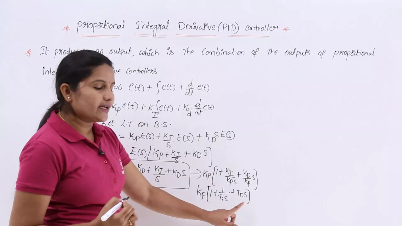
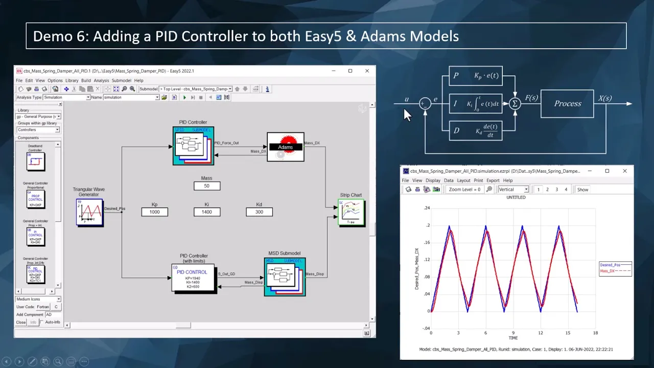
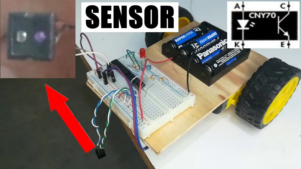
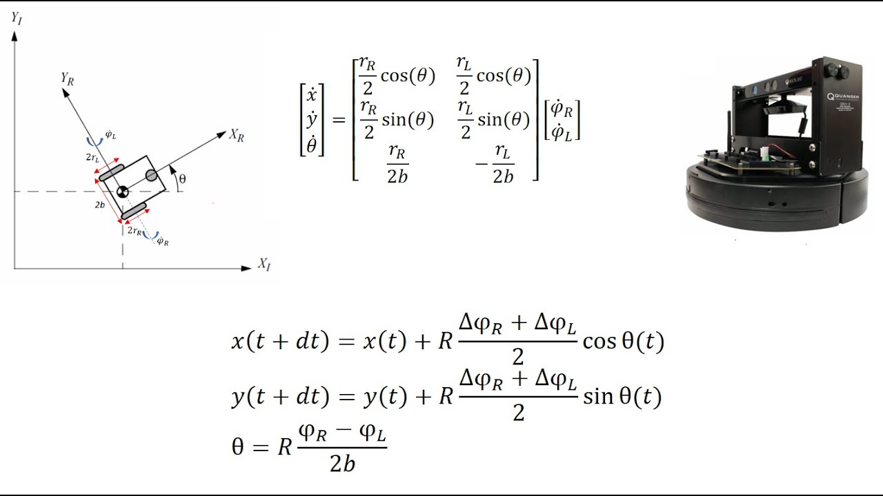
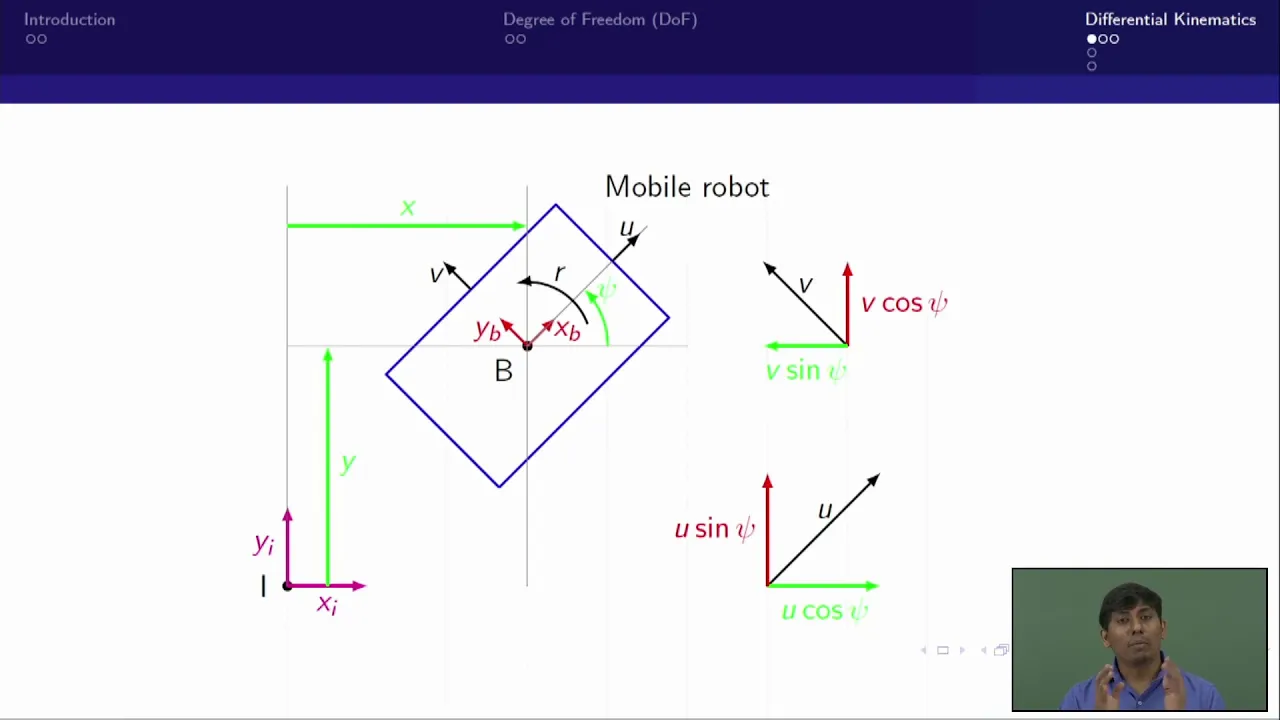
more online tracking the good news is that Duncan's done part of this for me so that's that's kind of Handy um consider for a moment a line follower which I would not necessarily build to look like this it's purely a representation um but you would typically have a robot body and a number of sensors okay which will stick with no more than four but that's fine and in this one I have made sure that they arrange two of them are over the line now in practice they would be slightly further apart don't get too hung up on the geometry right it's an illustration now you've made your line sensor you plonk it down on the line and you know that you want it to move along there and ideally not wander off into next door so you have to consider how things can go wrong and they can go wrong in several ways one way is that the mouse could be heading off with an angle error right it's Center is on the line but it's heading off next door and you don't want that excuse me um what's the other kind of area you can have well we'll call this an offset error right so we've got an angle error and we've got an offset error now the now the robot is parallel to the line but no longer properly oriented on it and but the sensors they can't tell well and of course you can combine these errors and still get the same sense of reading so you've got two independent errors which you need to correct do something about if you look Instead at a micromouse typically they will have walls to track and a pair of tracking sensors pointing at the walls I've put in here some little axes remember earlier I said we always would consider the robot in the X direction is the direction of travel and the Y Direction is uh 90 degrees to that and of course the micromouse in the Maze has exactly the same problems you can have an angular error and so the left sensor will get a larger reading than the right sensor you can have an offset error and the left sensor will get a larger reading than the right sensor and you can have a combination error and you have no idea what you've got going on none at all you cannot tell with two sensors we will I'm not sure if I can't remember if I do actually to be honest but notionally I quantify an offset error as e y and Theta for the angular error and the burning question when you you try to run either a line follower or a micro Mouse is how to correct this now one problem is that well let's first note that these are identical problems okay don't don't have any other illusion line following and wall following are exactly the same problem so if we can get a solution for one we get a solution for the other we have a robot with two independent errors what can we do about it you have to note that the robot is constrained badly constrained it cannot move sideways right and this has a huge influence on what we do well in engineer any kind of engineering if we've got something that needs to be controlled to within some limits what do we do we need some kind of feedback system right and so we have a process we have some kind of feedback measuring output and we have some kind of controller or compensator which looks at the error between where we want to be where we really are and just output some kind of control signal for what we want to do and if you don't know any different and even if you do no different you go searching around for prior art because that's always good okay who else has fixed this problem for me can I just do what they did and will it work and you generally come up with everybody says well we'll use a PID controller throw it just use a PID controller well in it take my word for it for the time being you don't need a PID controller but you probably do need a p and a D part right the integral part has its place for different kinds of problems and can be an essential part of the solution and in fact if you couch this problem in different terms you might end up with a pi controller but that's not what we're doing okay maybe you'll see maybe you won't I don't know so this is all very well this is classic stuff this is what you'll have you'll find if you go and look about or if you think back to those lectures from your dim and distant past when you were dreaming of the summer um the P term so we've got an error output input subtract them get an error still we don't know if we're dealing with a Y error or a Theta error right because we can't distinguish them it's just an error and we use a simple gain on that error for the proportional part and we have a differential term and here's something which nearly everybody seems to overlook if they're not doing this professionally and I don't don't get me wrong I'm not preaching or some kind of control systems expert I'm just reminding you of things that trick me up all the time the D term is acting on the rate of change of the error now it's this here which people mess up a lot there is a delta T in all this right it's the amount of change in error divided by the amount of change in time and if you don't take that into account you'll find strange things happen so this is generally what we do measure something correct it put it out and hope everything gets better well what does the robot system look like a robot our robot is some mysterious box of motors and batteries and electronics and it puts out what you can measure as its X position its y position and its angle in some absolute coordinates or relative coordinates it doesn't really matter that's all you can find out and these are the only things you can change yeah everybody happy with that don't want anybody coming back later and say well what if you change this or if you change that this is what you've got V and Omega forward speed angular velocity now you can look at it in other terms you can say well I can apply an angular acceleration and that will change the velocity and whatever but in the end that's what goes in that's what comes in it's actually obviously slightly more complicated than that it's a two-wheeled mobile robot so when you have a look at it in slightly more detail and I'll just give you a moment to do that okay right so this is the robot Dynamics this is the robot from the previous picture and there's an angular velocity going in there's a velocity going in and it does magic and you get some outputs here now you could try and measure these but how how are you going to do that we've already determined that you can't tell the difference between a wire and a an angular error so how are you going to do it difficult you could use a gyro integrate the gyro angular velocity turn that into an angle right and do that but you won't because you haven't got one probably and certainly at a basic level you're not going to have one foreign you could use the wheel encounters to try and get the angle but since you don't know what the angle should be that's not going to help you go and handle line following track how do you know instantaneously what the angle should be you know right in a maze you can kid yourself on that you know if it starts at zero you know that it should stay zero or be 90 or B minus 90 or whatever right um you can do that but you don't so what you do have though is the difference in the encoder counts which tells you about the angular velocity you do have the sum of the encoder counts which tells you about the forward velocity you can take this angular velocity ignore this compare it with your desired angular velocity generate an error feed it through a PD controller and so forth you can take your forward velocity compare it with your desired forward velocity feed it through a PD controller and so on all this is just a reminder that in fact the left wheel speed and the right wheel speed are controlled by V and Omega so your forward speed contributes directly to the left wheel speed and directly to the right wheel speed your rotational speed your angular velocity is the difference okay so you've got your control signal for angular velocity positive to the right wheel negative to the left wheel so positive angular velocity means you're turning that way or I should say that way right now what can you measure the only thing you can measure is that sensor difference that those sensor readings from the line sensor or the wall sensor there's no good feeding it back in here is there because that's just going to control the forward speed and you would like the forward speed to stay constant you don't really want to be speeding up and slowing down just because you've got an error I mean you can do that right and we'll have a look in a minute that quite often people do but it would be best if you had a constant forward speed so the only place left to put it is somewhere back in this angular velocity Loop and take my word for it because on a future evening session I will prove it right in a different talk the most convenient way to do this is to pretend that this error is an angular velocity it's not obviously but think of it as if it were there was a kind of rationale to it because um if you've got an error and you do nothing about it is it going to get better or worse if it's an angular error it's going to get worse if it's an offset error it probably won't um but anyway but my original intent for this talk was to talk about why this is so it turns out I don't understand it well enough to explain it and be certain that you follow me so I'll have to come back to that right there's there's some things which I've discovered whilst I was doing the work for this which made me question my my innermost beliefs uh the only thing that you might be upset about is that there is another PD block here okay and that's because I think people think of them as controllers and they're not the system is the controller what these blocks are are compensators right these are compensating for this error and driving the control system and so this is turning this fake line error into something that can be treated as if it was angular velocity and it's independent of the rest of the control so it's a PD block it has a proportional part it has a derivative part and we'll see in a bit how those contribute haven't seen the black area I'm surprising works at all I know all you do is transfer you in a bad data signal into it's obviously no doubt angular error and Analysis into hopefully one that's better well there is there is a proper derivation for this which would have taken too long today even if I could have done it without my notes in front of me yeah he's saying you've got proof that he does make it better yes right that's why I say for now take my word for it right on another occasion where you're really feeling bored um I can demonstrate that under a certain set of circumstances this is true right you you feed it back as you do at angular velocity and life is good so this is the bit that Duncan's done for me um I have or had I've taken it apart now UK Mars bot with four line sensors two marker sensors it's one of the standard board designs right I built them all tested them all verified they worked I've ran it at contests so that um I was confident before telling everybody to use it that it would work right so I don't want anybody coming back saying this doesn't work it does I know um what you have here is the result of reading the sensors as you get the robot to spin in the spot Over The Line right so it starts off parallel to the line spins through 360 degrees and this is the record from the sensors so you can see these are the marker sensors uh the response for the marker sensors is very different in two obvious ways one is it's much larger and another is that it's much flatter that's by design for the version I built because the marker sensors are really effectively binary outputs right I want them to just switch quickly when they detect a line whereas the line sensors have this triangular Shape close to Duncan's perfectly good model of a cosine okay I would only say that on this one I adjusted stuff so that they gave a pretty triangular pattern all right which is has its own benefits the reason it has particular benefits is you sometimes hear about people using a single sensor to track the line and you assume that this means it has to be bang bang but it doesn't because this if you just take any one of these that's a straight line right and you can ride that slope a bit like you would do for slope detection for FM radio or something you can ride that slope okay if you go off you're doomed but as long as you can still see something you're okay if you go off the wrong way and you end up on the other side you get positive feedback instead of negative feedback right and then it may come right it may not but you can use one Center and ride that slope if your sensors are set up like this you might notice um two other features see if you're paying attention now two other interesting features of the data whilst I have yet more to drink what would you expect to see which is wrong that's by Design just yeah I want to be certain that they're gonna see anything that even looks a bit like a no um they should cross this bit here it doesn't right they are all asleep uh and it's just because the robot was actually pushed off to one side and so it took more than 180 degrees to get back around and then slightly less to get all the way back around there the other is that um these lines don't come back to zero okay so um we'll get back to that Duncan's already done it but we'll get back to that so the obvious thing to do is to have a look at these two middle sensors and combine them um and the simplest way you can do that is the way uh I think Duncan described originally the uncompensated line here the red one you just take the left one minus the right one or the right one minus the left one don't do anything else with it and you get this slope around zero or 180 or wherever it's supposed to be in classic um systems you would divide by the sum so you could compensate this is there's nothing else going on right you would divide by the Sun so you can compensate for varying brightness if you were building a a radar system or a missile tracker you'd take the difference divided by the sun yes probably um thank you I'll see if I'll remember to correct it but you're quite right um if you do that two things will become apparent for reasons which slightly puzzle me I have to confess if you do the compensation the result is more noisy right because it's it's taking into account variations in brightness in the floor and all sorts of stuff you'd think it would cancel out but it doesn't and the other is that the slope is different why do you care because this slope is your game right that's your feedback gain and you're not you want to keep that constant as you as you make changes you can't just go around saying well I think I'll try compositing it because that'll fix this problem it'll change the gain and then all of your control system will be out right your constantly carefully calculated constants will have to be re-tuned so when you're looking at this do what you can to keep this slope the same one thing that we can do as Duncan's indicated is we can normalize our sensor responses so that the lowest value they ever have is zero the highest value they ever have is some nominal value of your choosing if you're using Arduino and you haven't seen it before there is a function specifically for this the map function right where you can take in your actual sensor value you can give it the smallest sense of value that you've ever seen you've recorded that in your calibration the largest one you've ever seen and say this is the range I want it mapped to and it's just it's built in you just feed your sense of reading through it and you get it back out it doesn't mean that these all come to the highest value but it means that each one somewhere does that it sorts out this is reasonably well put together so they don't need much compensation but if they were if they were different insensitivity this would fix it and that gives you a slightly better error function so what I've done in in this one which surprised me is I've shown several ways of calculating the error using these normalized values and I've multiplied them by minus one minus three one and three Duncan used minus one minus two I use minus one minus three there is a reason um which I forgot to make a slide for if that's your line and that's a sensor that's a sensor that's the sensor that's the sensor right these are all the same distance apart two units so that's zero one two three uh one minus one minus two minus three so that's why I've used those numbers um and the general explanation is that these numbers are proportional to the distance away from the line right and so that's uh that's waiting them then you can take the difference as before um they're all shown on one here it's a bit confusing so we'll skip the actual sensor readings and just show the differences so this is using just the middle two and this is using all four of them right exactly as Duncan showed earlier and you get two benefits one is you greatly extend the range so you're going plus or minus 30 degrees as opposed to plus or minus I know maybe 10 or 15 degrees by using more sensors you get a very linear response and going back to what I was saying earlier the slope is pretty much the same and doesn't change greatly just by adding more sensors quite a lot of code I've looked at by the way uses the add up all of the left ones and add up all of the right ones and not do the waiting um although it's not great uh out here you still have a steering function you still have an error it's just not as big as you might like right so the difference is still positive or negative and so you'll still get a steering function from a logical point of view shooting in you know those outer walls are wrong because you've got signal for your innocence but that doesn't mean you don't have a valid steering solution outside that range in the right direction you're still moving it you've still got an error of the correct sign and you're still moving in the right direction it's just no longer linear all right yeah I mean from because you've got multiple senses you know that that's outside yeah I I mean in practice if I was building a contest one I'd have you know six right I used to say yeah the clubs oh as you go down here yeah oh well yeah life's never great you don't want it you don't want to get out here I'm just saying that you still have something that tells you I've got to turn right yeah so when you have a look at the this now we've switched over to um a maze solver right just because these problems are interchangeable and I've got a left sensor and a right sensor I always display the right sensor as a negative value because if they all overlay each other it's hard to see what's going on and I can kind of contort myself to imagine I'm going down a corridor this way and that's the one on the right and that's the one on the left okay so it helps me to mentally map it and it makes it easier to see right sensor left sensor I think I don't even know if it's at constant speed but it's moving across a total of six cells and there's a wall at the end and you can see the posts by the way and you can see that the walls are different so we've got a a dark wall a light wall a dark wall or a pair of them you can see that you can use the value of the front sensor to tell you when the side sensors are becoming unreliable because they're also seeing the front wall right you get quite a lot from this and notice also that I always plot distance on the x-axis not time because that's the important thing in many ways but look these sensor readings are pretty noisy I I see people bang on about wanting to have 12 bits of of analog resolution on their sensors this has got eight bits and there's noise in it right I've thrown away four bits of ADC resolution and that's still noisy don't get carried away you don't need it it's a problem and remember what I was saying earlier about the differential term in your controller right this is looking at changes these are all changes and if I have a look at the D term that I get from my controller it's magnified for dramatic effect but you can see it's banging around all over the place it's not great what can I do well the simplest thing to do is to low pass filter the sensor readings right use a software filter on them that makes it doesn't change anything about the information by the way you can still see the posts you can still see the different walls it won't materially affect the performance of your control system but it will fantastically reduce the noise and nonsense that you get from the derivative part of your controller okay and that's um an important consideration the low pass filter is an exponential moving average filter if you're not have you anybody who's not seen that before all right um remind me I can send out links or look it up it's an exponential moving average filter you can rearrange it and do it with one multiply one ad per cycle so it's very cheap process of power very cheap yeah yeah so this in this particular case it is ten percent say that summer if you made that up so yeah right so yes it it just adds a small proportion of things that's going to give you a lap it doesn't matter for the controlled system doesn't have any difference you won't notice I mean if you want to model it up and add it into the controller I'll find you and I'm just saying that this this is not enough to actually for the job it has to do yeah ready would you say you just feed that into the steering that's because look at the edges and things you wouldn't oh well um how do we do it uh this is the steering function this is actually from our wall follower but the same thing we'll do for a line follower I assume this is calculating the steering error assume it's nothing so one of the questions people have with them with a micro Mouse is what do I do if there's only the one wall or if there's two walls or no walls um if there's you you find out what your right error is what your left error is different you know just the difference between that and the nominal value that you've calibrated if both walls are there just take one from the other if only one wall is there only use the corresponding error but for goodness sake remember to multiply it by two because if you don't your slope is half your gain is different and your steering function won't work once you've got your steering error you have to turn it into an adjustment value so we're now in that PD block right we've we've done our feedback we've done some sums on it to get a number and then we go to the PD controller the piece of them is easy it's just my constant times whatever the error is the D term is my constant times the change in error divided by the loop interval the DT term put it in nearly everybody who shows you how to do these things leaves it out they just put in some arbitrary value or they give you advice on how to calculate the D term and that advice is meaningless if it hasn't Incorporated how did that happen if it hasn't Incorporated the loop interval right because sorry no it's not ready to change if you're not doing that right or more accurately the number that they have shown in their example includes this correction right and so you might get a number that's like 3000 instead of three um and you can you can't work out why what how can it be that it's nonsense right so oh yeah if it's a one million if it's a one millisecond cycle time right [Music] yeah they've done it in their sums because they were taught badly how to do it right it says oh you you increase your P term till you get some oscillation back it off increase your detail we talked about all this before in an evening session um but it means nothing if you're not correcting for the for the loop interval not least because um if you then decide to change your Loop interval or little change right but if you change your Loop interval now it's taken into account and if you don't like the Divide then count pre-calculate a constant which is just your Loop frequency and do a multiply yeah so if you pre-calculate the steering KD divided yes if you look up there's um I can't remember his name now there's a guy done a series of articles about the improving The Beginner's p p IDE controller which you'll find on and he correctly identifies all of these things but doesn't make a big thing of it so it might you you can miss it in the explanation um this is a debatable part right so here's the question I'm gambling now because I'm running a lot of run out of time but if you go faster should your steering correction be bigger or smaller what's Your Gut Feeling if you haven't already worked it out and if you do the research you'll get both answers yeah because when you're driving a car um you're interested in getting back on track after the home's gone yeah right but you can't afford to do it too violently and what you're concerned about is how quickly you get back on track not how far you have traveled whilst you're getting back on track if your requirement was I had better miss that Bollard right you're going to steer harder aren't you so it kind of depends on how you couch the problem and if your problem is in terms of let's say I must correct an error within two cells you definitely need to be steering harder at speed that's the thing you want to do the same thing you want the same curve at the highest speed as you do at the lowest speed so the same thing exactly so I think this is another thing I can't improve rigorously but I will do sorry well these are all subject to some surprising amount of debate right and it all depends on how you derive the problem I have seen perfectly good mathematical derivations which have completely opposite outcomes in terms of whether you know which bit should be proportional which isn't I'm suggesting as a good first approximation make the whole adjustment proportional and this is speed over Speed Max explore and this is because you typically only get to tune your robot at a given speed you don't get to tune it at lots of speeds and so if it's correct at that speed then this will be one right if your speed is that speed this adjustment will be one and if it's higher it'll be bigger if it's not it'll be smaller there should also be a term in here which um stops it being zero that will do that you remember the last error for the DT terminal there you go this is equally valid for a line follower right because you have the same problem you don't want to be back on the line sometime later today you want to be back on the line within I don't know six Mouse links or whatever whatever your requirement is um oh and then this is the actual rotation controller itself um I've got there's a an error in uh in angular velocity which is what the current angular velocity is minus what it should be I have a flag in which lets me turn off the steering right but I still calculate it so that if I want to log it and see what it would have been I can still do that but I can turn it on and turn it off this is what I was saying this morning about turning on and turning off the steering at different points of the explore then you do this this now is that other d block right in the angular velocity feedback there's a whole set of terms for that and then you get the output and the bit with all the nasty arrows is just this I've got a forward result an angular velocity result Ford is left sorry add them together for the right output subtract them from the left output turn them off it's going down zero right just leave it at zero right you have no no well that's the thing right so whilst you are just following the line first time around set your your controller angular velocity to be zero then if you're clever once you've judged the radius of curvature of the of that curve and you've decided on a speed from that you can calculate what the angular velocity should be to get around that and that's that becomes like a feed forward term right and then you say once I've hit this turn marker I want to set my angular velocity to be 25 degrees per second right and then that goes in there and now as we've seen before your controller is compensating for errors from that rather than from zero right so the second and third time round you hopefully would have an idea of what Omega should be and you're trying to drive the robot to do it and then the controller is just keeping you within limits um so apart from anything else what should you take away be consistent if you've calculated controller gains make sure that you don't do anything to upset the slope of the of the feedback function that's the main thing right um and you do that best by normalizing uh your sensor responses uh using known good test cases and working away from them um don't go reading how to do this and assume that anything that you read anything that you read including mine is applicable to yours right unless you're doing everything the same way and since people very rarely explain the inner workings you can't know that so it's a problem um always use real units wherever possible you can pretend you know that this is the the error is so many degrees or degrees per second I don't care but working degrees millimeters seconds right don't use arbitrary sensor units clicks of the encoders widths of a grain of sand usual units because otherwise you can't communicate with anybody else especially if you're all working on the same class of robot oh mine's got a feedback gain of 63 63 what if we haven't got the same units there's no not even any point in the same and then make sure that your differential term accounts for the loop time now I think I've actually really overrun yes badly yes you're taking um [Music] is that every time your sample says and on the field the temperatures no well it will right because it's all taken account was elsewhere it does it's arbitrary it's just a low pass filter I just wonder what the knee was eventually try to calculate it has a time constant of five sample times I think so it depends on you obviously it depends on your sample frequency there's nobody knows something very quickly no I just wanted to watch like could have been a disease into the frequency domain honestly I wouldn't worry about it um a couple of quick things if I may one is um somebody asked me about going around the wall around the post right um it will take me too long to find the slides I can show you separately but if you use that low pass filter you've got some data and as you're all gone right if you have a reasonably fast low pass filter and a very slow low pass filter um on the same data okay and you subtract one from the other you'll get nothing here whoop and you found the edge right and it's cost you almost nothing just these two filters one of which you were going to use anyway and one of the things you can do is you can say if this slope because this is a measure of the slope of that if this slope is high don't trust the sensors for steering anymore right so that tells you you've got an edge your sensors are dangerous don't use it or you can look directly at the derivative and say if the derivative is is too large that means there's a slope don't trust the sensors anymore pretend that they're working fine does that answer that question yeah yeah so also this is one advantage of searching quickly the faster you go the less of a problem if you go around very slowly you can suddenly find you go right around the corner first one but if you're going quick it'll disappear and it won't be as much of a problem and yes this is a simulation of a steering problem um if I start off with a Y offset of 10 millimeters I'm not going to crash okay top graph is my my error my y error and it's now reduced to zero but if I start off with an angular error clearly I'm going to crash right blue line goes off hit the walls lose the sensor whatever I need to correct it I can do that with my pde controller I can add even a small amount of P right and I get quite a decent result I haven't added any derivative term this line here is when the error drops to within I think five percent or something um if I add in a little bit of d uh looking the wrong way right it settles sooner but down here we've got the speed we're doing it exploration speeds very slow 500 millimeters a second that's the speed if I allow it to go faster right it takes me longer to settle if I start the whole thing off faster this is my speed at the beginning of the track it gets worse and the faster I go recognize this Behavior right it's because you've gone faster it's getting out of control and so what do you do well you go oh my god I've got to increase the Gain No that's not helped maybe I have to increase the derivative term that's not helping I'll run through this properly and we do an evening session about how to work out a proper control law thank you I assume
Up Next
21:22
UKMARSBOT Mazerunner Core: Micromouse Software Architecture Guide
@MicroMouse
2K views•2023-09-09

58:25
MathWorks Virtual RoboSub Simulation Environment | Webinar 2026
@RoboNationInc
209 views•2026-03-10
73:33
Encoder-Based PD Controller Design for Micromouse Robots
@MicroMouse
6.7K views•2022-12-06

25:22
Micromouse: The Fastest Maze-Solving Robots on Earth
@veritasium
23.5M views•2023-05-24
Related Study Plans & Knowledge Roadmaps
Structured learning paths in Robotics
robotics
Building Delta Robots: Kinematics & Pico
01Foundations of Delta Robots & Mechanical Design
02Electronics and Microcontroller Setup with Pi Pico
03Delta Robot Kinematics and Coordinate Math
+ 3 more learning modules
65h6 modules
Explore Roadmap
robotics
Building Ballbots: Dynamics, Kalman & LQR
01Embedded Electronics & Omniwheel Actuation
02Ballbot Kinematics & Rigid Body Dynamics
03IMU Sensors & Kalman Filter State Estimation
+ 2 more learning modules
42h5 modules
Explore Roadmap
robotics
Micromouse: Hardware, PID Control & Flood-Fill
01Electronics & Teensy Microcontroller Basics
02Sensors and Actuators: Motors, Encoders & IR
03Precision Movement: Implementing PID Control
+ 2 more learning modules
35h5 modules
Explore Roadmap
robotics
CDPR: Kinematics, Arduino & Winch Control
01Foundations of Arduino & Basic Electronics
02Stepper Motors and Winch Mechanics
03Kinematics of 2D Cable-Driven Robots
+ 2 more learning modules
28h5 modules
Explore Roadmap