


![Silniki DC | cz.2 - Mostek H | #64 [Podstawy]](https://i.ytimg.com/vi/YMECxKCmrfw/maxresdefault.jpg)


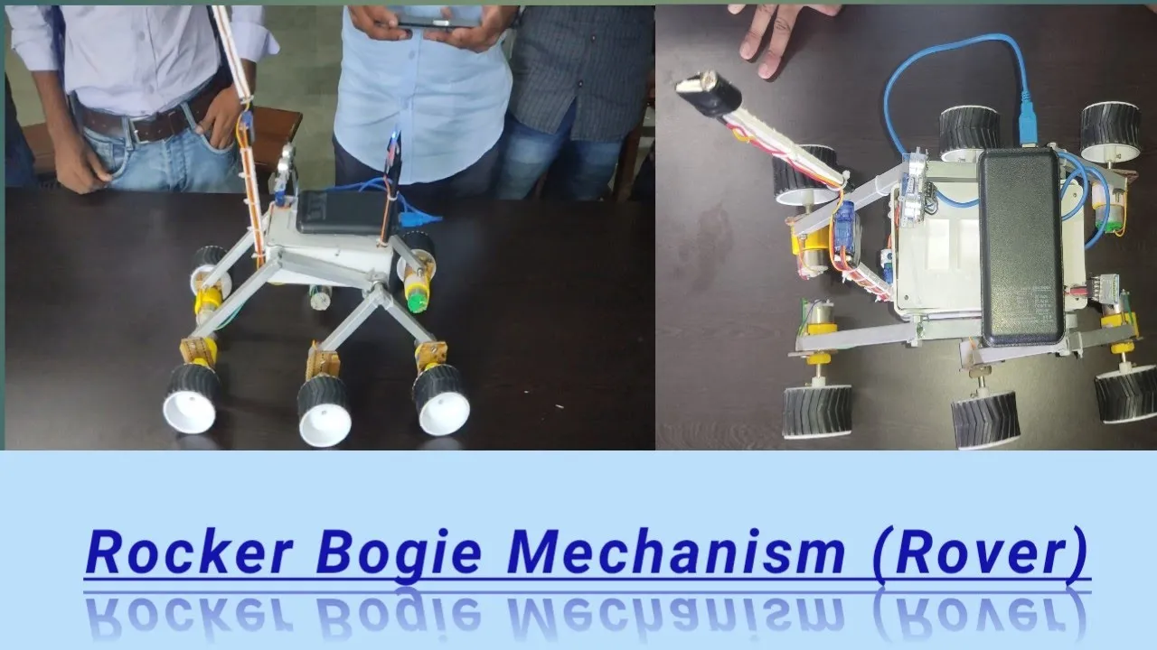


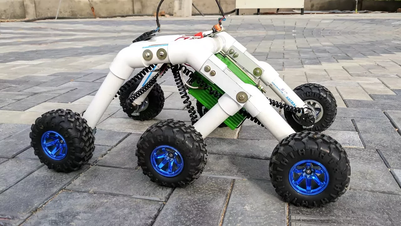











This video demonstrates how to build a functional replica of NASA's Mars Perseverance Rover using Arduino mega, rocker-boogie suspension with Ackermann steering geometry, six independently driven wheels, and FPV camera capabilities. The project uses 3D-printed parts designed in SolidWorks, aluminum profiles for the frame, and commercial RC components for control. The rover features custom PCB for motor drivers and servo control, with code implementing Ackermann steering calculations to enable smooth turning by adjusting wheel angles and speeds based on turning radius.
How I Built an Arduino Mars Rover Replica: Full Guide
Added:Basic Arduino programming (C/C++) and electronic circuit design, including handling GPIO pins, sensors, and external power supplies.
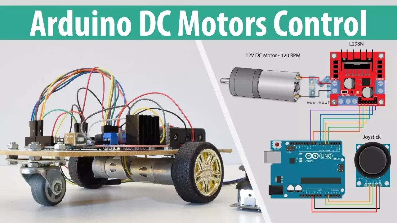
Fundamentals of DC motor control, servo motors, and utilizing H-bridge motor drivers to regulate speed and direction.
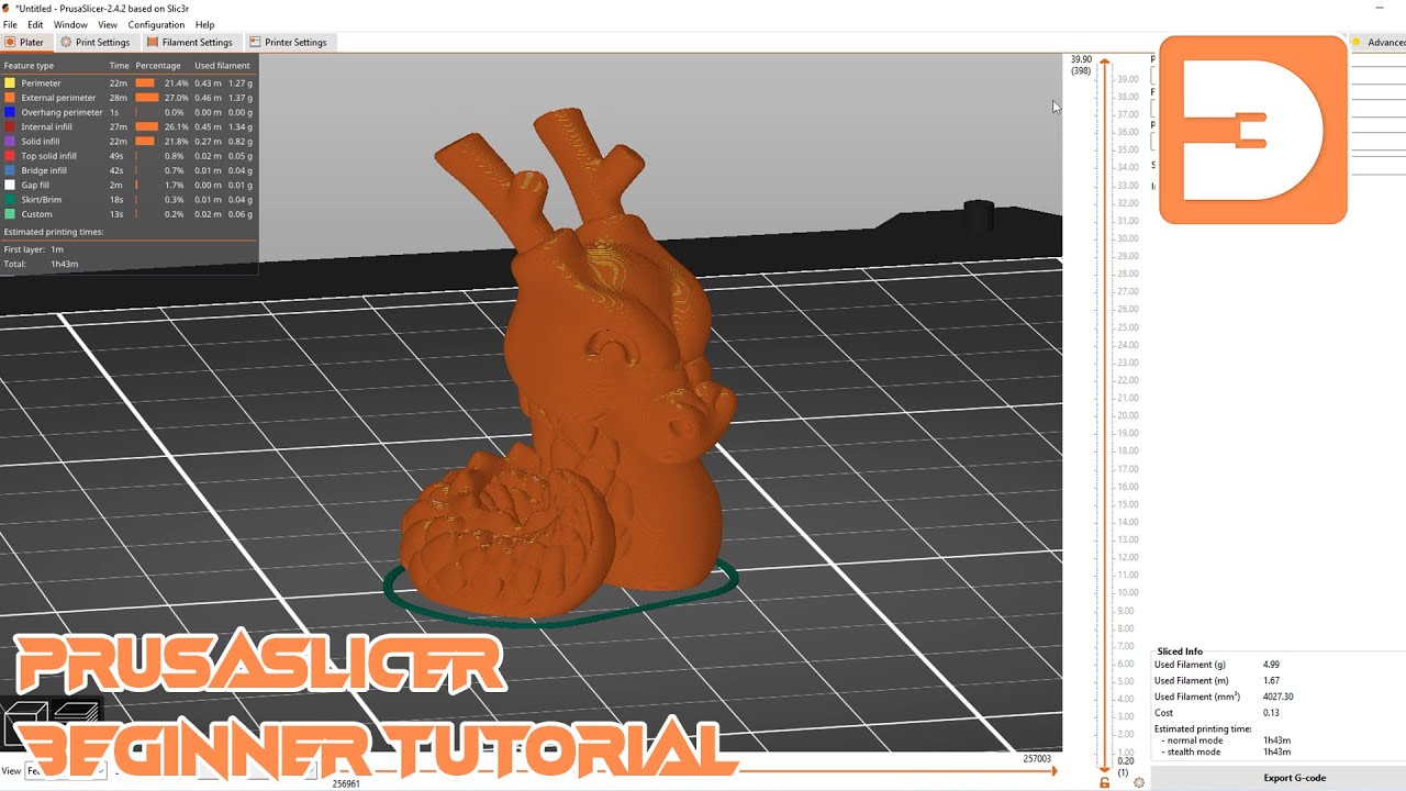
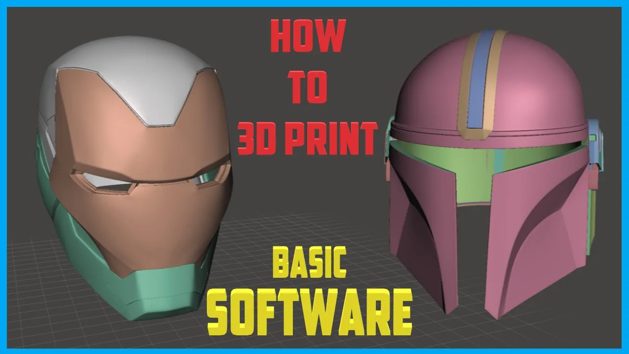
Introduction to 3D printing workflows, including slicing software, print settings (infill, supports), and basic CAD assembly concepts.
Core mechanical engineering principles of suspension, specifically the mechanics and physics of the passive rocker-bogie mechanism.
Integrating ROS (Robot Operating System) with Arduino to manage advanced robot navigation, localization, and mapping.
Implementing autonomous pathfinding and obstacle avoidance using LiDAR, ultrasonic sensors, or computer vision (OpenCV).
Developing wireless communication and telemetry systems using LoRa, Wi-Fi, or Bluetooth modules for long-range remote operation and data feedback.
Designing advanced power management systems, including lithium-ion battery management (BMS) and solar-harvesting integration for extended mobile operations.
565.3K views12.5Klikes24:28Original Release: 2021-06-03
[Music] hello dan here from howtomechatronics.com and in this video i will show you how i built a replica of the mars perseverance rover of course inspired by the real rover which is currently exploring mars i designed this rover in a way that everyone who loved this technology students makers mechatronics or robotics enthusiasts and so on can easily follow the instructions in this video and build their own mars rover let's take a look at the main features of this rover it employs a rocker boogie suspension which allows the rover to run smoothly on uneven terrain and climb obstacles such as rocks that are up to twice the wheel's diameter in size while keeping all six wheels in contact with the ground all the time each wheel has independent dc motor which drives the rover forward or backward the four corner wheels have individual steering servo motors in order to efficiently steer the rover and avoid tire sleeping when driving around the curve we are implementing the ackermann steering geometry with this geometry we can calculate the speed and angle of each wheel depending on the turning radius this means that when turning the inner steering wheels will have greater angle compared to the outer wheels at the same time the inner wheels will have slower speeds compared to the outer wheels for controlling the rover i am using a cheap commercial rc transmitter which sends commands to the rover at the rover i have a suitable rc receiver which receives the commands and sends them to an arduino board yes the brain of this mars rover is actually an arduino mega board and for easily connecting everything together i made a custom pcb which can be simply attached on top of the arduino mega board the rover also features an fpv camera located in the cameras unit it is controlled using a stepper and a servomotor and i am receiving the real-time video on a smartphone i would like to note here that many of the parts are actually not functional or they are present just to match the appearance of the real rover also the robotic arm is missing but i plan to make the arm and add more functions to this drawer in future videos nevertheless now let me walk you through the process of building it starting from designing the rover connecting the electronics components and programming the arduino board i designed this mars rover using 3d experience solidworks which are actually the sponsor of this video 3d experience solidworks is a version of solidworks with cloud capabilities which we get through the 3d experience platform here everything works through the cloud so you or anyone from your team can have access to the data or the models at any time from anywhere in the world the 3d experience platform also includes many useful productivity and data management apps for example the project planning app is great way to organize your tasks set deadlines and keep track of your progress with the 3d markup app you can view explore and take notes of the models from any device like a notebook tablet or even a smartphone there's also a separate cloud-based 3d modeler called solidworks x design that runs inside your browser it can be used in conjunction with solidworks or on its own and it's great for modeling anywhere anytime and on any device nevertheless probably the most exciting news for many of you guys here is that starting from second half of this year there will be a maker version of 3d experience solidworks which you can get for only 99 per year so make sure you check out the links in the description and sign up to get notified when it will be available big thanks to solidworks for sponsoring educational content like this okay so let's get back to the model now and explain how i designed this rover my goal was to make this rover look as close as possible to the real mars perseverance rover on the official nasa website there is a 3d model of the mars perseverance rover so i download it and opened it in blender i took three pictures of the front top and side view of the rover and imported them in solidworks i wanted the size of the wheels to be 130 millimeters in diameter so i scaled the pictures according to this dimension then from here i took all key dimensions like the width length height distance between wheels dimensions for the rocker backing suspension and so on now according to these dimensions and the dc motors and the servos that i plan to use i designed the rover parts in a way that they can be easily 3d printed and assembled while trying to keep the appearance as close as possible to the original for the rocker boogie suspension i am using 20 millimeters round aluminum profiles whereas for the base frame i am using 20 millimeters t-slot aluminum profiles in order to assemble the rover we need various bolts and nuts and bearings and you can find a complete list of all components needed for this project on the website article of course you can also find and download the 3d model as well as the stl files needed for 3d printing the link is in the video description for 3d printing the parts i used my old creality cr-10 as well as the new cr-10 version 3 3d printer if you want to print the wheels in flexible material you will definitely need a printer with direct extruder just like the cr-10 version 3 is both of these 3d printers provide great printing quality while being relatively affordable so if you are interested there is also a link to them in the description so you can check them out when 3d printing the parts it's important to use the horizontal expansion feature in your slicing software i used a value of minus 0.1 millimeters this feature compensates the expansion of the filament when printing if not used for example if the part has a hole with diameter of 20 millimeters the hole of the actual 3d printed part will be around 19.8 millimeters and we won't be able to assemble it nevertheless here are all of the 3d printed parts to be honest it's a bit crazy how much printing there is but it's the only way we can get the unique appearance of the rover though you can cut the printing time in half if you choose to print only the functional parts of this rover alright now we can start assembling the rover first we need to prepare the aluminum profiles i use the metal hand saw to cut them to size we need 10 t-slot profiles for the base and 8 round profiles for the rocker boogie suspension for assembling the t-slot profiles frame we are using a suitable t-slot corner brackets and some bolts and nuts once we have the top and the bottom frames ready we can complete the base by inserting the rocker joint 3d printed parts on the sides and some 3d printed brackets on the front and the back for securing them in place we need m3 bolts and t-slot nuts for the rocker joints i used m5 bolts and nuts the distance from the front profile to the rocker joint needs to be 134 millimeters next we can insert the main bearing for the rocker boogie suspension in place then we have the rocker joint shaft which will be attached to the base using an m8 bolt the shaft has a slot where we can insert an m8 nut which is used for securing it to the base the hole of the shaft is 7.5 millimeters so that we have a tight connection between the bolt and the shaft in this way we actually reinforce the 3d printed shaft as the bolt itself will carry some of the weight of the rover this is the most stressed part of the whole assembly as the whole weight of the rover is supported with this rocker shaft however the way we print the parts plays significant role for their strength i initially printed this shaft the easier way where no support material is needed but the print failed in this way the main stress force acts on the layers which are not that strong but if we print the parts sideways where the stress force will act on the wall contours the part will be way stronger and won't fail nevertheless now we will continue with assembling the rocker boogie suspension together with the wheel joints and the motor mounts and later we will attach this sub assemblies to the rocker shafts the holes of the parts where the 20 millimeters round profiles go are dimensioned to have a tight fit so in some cases we need to use a rasp or sanding paper to make them fit now for properly assembling these parts we need to make holes in the round profiles at precise locations for that purpose first we will mark a straight line on the profile next we can insert the profile into the 3d printed part with the marking line passing through the hole of the part then we can mark the locations where we need to drill the profile on both sides of the part on the opposite side of the profile we need to repeat the same procedure i drilled the holes using a 2.5 millimeters drill and then using a m3 bolt i made a thread in the profile which we will use for tightening the parts the aluminum profile is softer than the bolt so it's easy to make the thread with the bolt itself following this method for drilling the holes is very important so that at the end all of the parts are positioned as they should be relative to each other for the boogie joint we are also using two bearings and an m8 bolt once we complete the rocker boogie suspension arrangement we can continue with assembling the steering wheel joints the steering wheel joint part is composed of two parts bolted together for the actual joint or the connection between the servo mount part and the dc motor mount part we use two bearings and an m6 bolt at the top side or the head of the bolt we need to attach a servo horn and we do that with the help of this 3d printed coupler and some m3 bolts the coupler has a hexagonal slot through which the servo motion will be transferred to the bolt at the bottom side we can screw the other part of the joint we secure this connection with an m6 nut this completes the steering wheel joint although later on i will realize that we actually need to add another m6 nut at the bottom and tied it to the other nut we need this because the motion of the servo is transferred to the dc motor mount part using the nut itself and if not tightened with another nut the whole joint will unscrew the same procedure goes for the other corner joint we know we have connected everything properly if we place this assembly on a flat surface and all three motor mounts lay flat or all of them are parallel to each other of course we are using the same method for assembling the other side however we can note here that although some of the parts look identical they are not the same parts but they are actually mirrored next we need to insert these sub assemblies onto the rocker joint shafts on the base frame or the chassis before we do that though we need to insert some threaded brass inserts in the shaft using a soldering iron we can easily insert them in place and so we get a good and reliable threaded holes for securing the suspension sub assembly we use four m4 bolts for that purpose once we install them on both sides we can notice that the chassis falls or rotates freely so we are actually missing something in order the rocker boogie suspension to work properly and that's the differential with the differential the two rockers are connected to each other and the rover chassis with this configuration when one side rotates the other rotates in the opposite direction thus providing approximately equal wheel contact the chassis will have an average pitch angle of both rockers here are all of the parts needed for assembling the differential as the differential bar is quite long i made it out of three pieces bolted together so that we are able to 3d print them even on smaller 3d printers the differential bar will pivot in the middle of the chassis with a joint made of two bearings and an m8 bolt for connecting the differential with the rockers we need a rod end ball joint i'm using a m8 rod and ball joint and we also need an m8 threaded rod with 50 millimeters length the threaded rod goes into the 3d printed part which has an m8 knot on one side and on the other side it goes into the rod end ball joint here we need to adjust the distance between the 3d printed differential link and the rod end which needs to be around 20 millimeters in order the chassis to stay horizontal for connecting the differential into the rocker lever we are using two bearings and an m5 bolt we repeat this procedure for the other side as well and with this our rocker boogie suspension is completed when one side goes up the other side goes down and vice versa this provides all wheels to be in contact with the ground all the time the chassis goes only half the motion of the leg or the chassis has an average pitch angle of both rockers okay so next we can move on with installing the dc motors the motors that are used are 37 millimeters in diameter operating at 12 volts and have a gearbox with output of 50 rpm however i later realized that 50 rpm is a bit too much for this rover so i would suggest choosing 20 or 10 rpm versions for attaching the wheels to the motors i made these shaft couplers here we need to install m3 threaded inserts which will be used for securing the coupler to the shaft and also aim for nuts for securing the wheels to the coupler when inserting the nuts we should also add some glue so they stay in place firmly or use threaded inserts instead next we can attach the wheels the wheels are composed of two parts one is the wheel which is printed in flexible material but it doesn't have to be and the other is the rim printed with normal pla the rim has slots which fit into the wheel and so the power from the motor is transferred to the wheel here we can add few drops of glue at the slot to have them more secured finally we can attach the wheels to the shaft couplers or the dc motors using 4 m4 bolts next we can install the steering servo motors i'm using high torque digital servos with 25 kilogram centimeters torque and operating voltage from 4.8 to 6.8 volts for securing the servos in place we use four m4 bolts which go in the m3 threaded inserts in the servo mount 3d printed part all right so next we can assemble the cameras unit for panning the camera i decided to use nema 17 stepper motor but you can also use any other type of motor here the motor motion is transferred to the upper section using a m5 threaded rod which is connected to the motor with a 3d printed shaft coupler and on the other side we use a bearing and two nuts for securing the threaded rod for tilting the camera i am using a servo which is the same as the one we use for the steering wheels many of the parts here on the camera unit are actually not functional and they are present just to match the appearance of the real rover for assembling these parts we need various m3 bolts and some threaded inserts however i will also install a real fpv camera here i made a custom holder for it so i can mount it on the housing of the camera unit the camera is easily accessible from the top which we can close it with a snap fit cover here's the final appearance of the camera unit i mounted this whole camera sub assembly in the front right corner of the chassis at this point we can continue either with assembling the rest of the 3d printed parts which are actually not functional but only to match the appearance of the real rover or connect the electronics components and get the rover working i decided to assemble all 3d printed parts first and then do the electronics just like i said the following parts are just for matching the appearance of the rover so i won't go in details how i assembled them you can see how everything needs to be connected from the 3d model i actually put a lot of effort designing these parts paying attention to details in order everything to looks good these parts are also quite big and take some time to 3d print them the last two panels in the middle of the rover are designed to snap fit in the rover they will actually act as a hood which can be easily removed as the electronics components will be located in this area the electronic components holder is made out of two 3d printed parts bolted together and it goes to the bottom frame of the chassis alright so now we can continue with the electronics first we need to measure how much wire we need for each motor i soldered the wires directly on the motors as i didn't have proper motor connections i used heat shrink tubing for isolating the connectors with the help of some zip ties we can guide and keep clean the wires for the servo motors we can use servo extension wires to extend the wires to the electronics compartment the electronics mount part has holes through which we can pass the wires to the middle of the rover overall i think the wiring came out quite clean with the wires passing behind the visible parts let's take a look at the circuit diagram of this rover now and see how everything needs to be connected for driving the six dc motors we are using six drv8871 dc motor drivers which support pwm control and up to 3.6 amps of peak current the dc motor's operating voltage is 12 volts with rated current of 1 amp and stall current of 3 amps for powering the rover i'm using 3s lipo battery which provides around 12 volts the servos on the other hand need from 4.8 to 6.8 volts so therefore we need to use a dc to dc converter which will convert the 12 volts to 6 volts the converter needs to be able to handle around 8 amps of current as the servos that we are using are quite powerful and have a stall current of around 2 amps for driving the camera unit stepper motor we can use an a4988 or drv8825 stepper driver using two resistors we can make a simple voltage divider through which we can monitor the battery voltage the rc receiver is powered with 6 volts coming from the bug converter and the fpv camera in its video transmitter are powered with 12 volts from the battery in order to keep the electronics components organized i designed a custom pcb for this rover the pcb will actually act as an arduino mega shield as we will be able to directly connect it on top of the arduino mega board in addition to the motor drivers i also included a 3.3 volts voltage regulator and a dedicated nrf24l01 connection in case we want to control the rover using that module as well as many other connections which can be used for attaching various sensors and modules actually i tried to future proof this pcb for upgrading the rover's functionalities i ordered the pcb from pcbway here we can simply upload the gerber file choose the properties for our pcb and order it at a reasonable price i didn't change any of the default properties except for the pcb color which i chose to be blue in order to match with the arduino board you can find and download the gerber file on the website article or from the pcbway project sharing community through which you can also directly order this pcb after several days the pcb arrived the quality of the pcb is great and everything is exactly the same as in the design assembling the pcb is pretty straightforward as everything is labeled i started with soldering the pin headers at the bottom of the pcb for the arduino mega connection and then continued with the top side i actually used pin headers for all connections because it gives flexibility to make changes if something doesn't work properly i didn't solder the 3.3 volts voltage regulator as well as some other free arduino pins as i wasn't going to use them now anyway once i finish with the pcb assembly i secured the arduino board to the electronics mount part using two bolts and then added the pcb to it then i connected each motor to their drivers and put them in place in the pcb the servos go in their appropriate servo pins as well as the stepper driver for which i used one jumper for selecting a stepping resolution for the radio communication i am using the flysky rc transmitter and receiver which are really affordable and work great for connecting the receiver to the arduino we can use servo extension cables as we need three wires vcc ground and the signal pin the receiver communicates with the arduino through an ibus and a serial port if you want to send data back from the receiver to the transmitter in our case for monitoring the battery voltage we also need to connect the sensor ibus of the receiver to another arduino serial port the back converter is secured in place using two bolts and for securing the lipo battery i am using two rubber bands so in that way i can easily remove the battery for charging the power switch goes on the back right panel of the rover make sure you double check your connections with these wires because if you connect something wrong you might fire up things lastly we can connect the fpv camera to a 12 volts power supply and connect the video signal wire to the video transmitter which also needs to be powered with 12 volts with this we are done with the electronics we can put back the cover panels in place and we are done with this project actually we are almost done as we need to give life to this rover now or program the arduino here we will take a quick look at the code and on the website article you will be able to find more details on how it works so using the ibus bm library we read the incoming data from the rc transmitter then we convert these values into turning radius to right value turning radius to left value and rover speed from 0 to 100 percent we use the turning radius r value for calculating the steering wheels angle as well as the speed of the wheels as i mentioned earlier we are using the ackermann steering geometry for calculating them these values are then used for controlling the servos using the servo easing library which provides smoother servo movements and for controlling the dc motors using the analog write function which actually sends pwm signal to the dc motor drivers overall the code is not that complicated as the rover itself doesn't have complicated functions however i do plan in future videos to add more functions to this rover like gps navigation various sensors robotic arm soil collecting mechanism and so on nevertheless that's all for this video i hope you enjoyed it and learned something new if you have any question you can ask them in the comments section here or on the website article don't forget to subscribe and for more tutorials and projects visit howtomechatronics.com
Up Next
10:11
Building a 2DOF Robotic Shoulder Joint with Brushless Actuators
@Skyentific
61.4K views•2019-06-18

30:32
Ultrasonic Transducers: Resonant Frequency Measurement and Horn Design
@imajeenyus42
229.9K views•2017-02-22
24:43
3D Printed Gears: Strength, Efficiency & Materials Guide
@HowToMechatronics
176.8K views•2024-06-09

33:39
How a Student's Question Saved a NYC Skyscraper from Collapse
@veritasium
22.8M views•2025-04-26
Related Study Plans & Knowledge Roadmaps
Structured learning paths in Engineering
engineering
Building Acoustic Levitators: Physics & Arduino
01The Physics of Sound and Standing Waves
02Piezoelectric Transducers and H-Bridge Drivers
03Arduino Programming: Generating 40 kHz Signals
+ 2 more learning modules
14h5 modules
Explore Roadmap
engineering
Building Peltier Cloud Chambers: Particle Tracks
01Cosmic Rays & Cloud Chamber Physics
02Thermoelectric Cooling (TEC) Fundamentals
03Custom Liquid-Cooling Loop Design
+ 2 more learning modules
18h5 modules
Explore Roadmap
engineering
Yagi-Uda Antennas: Modeling, Build & VNA Test
01Introduction to RF and Antenna Fundamentals
02Yagi-Uda Antenna Design Principles
03Antenna Modeling and Simulation in 4NEC2
+ 2 more learning modules
18h5 modules
Explore Roadmap
engineering
ECG Monitor Design: Op-Amps, Filters & Noise
01Electronics & Breadboard Basics
02Op-Amps and Instrumentation Amplifiers
03Bioelectricity and ECG Fundamentals
+ 2 more learning modules
18h5 modules
Explore Roadmap