A closed-loop stepper motor system uses a magnetic encoder (AS5600) to provide real-time position feedback, allowing the controller (ESP32) to compare requested steps against actual rotor position and instantly correct errors through a PID loop, preventing step loss in 3D printers and CNC machines even when the bed is bumped.
Closed-Loop Servo Control for 3D Printers Using ESP32 and Klipper
Added:Deep Dive
Understanding the differences between open-loop stepper motors and closed-loop servo systems, including the role of rotary encoder feedback.
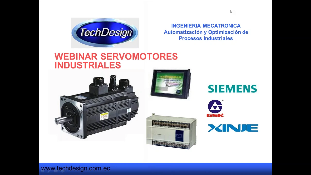
Curso (Webinar) - SERVO MOTORES INDUSTRIALES GSK / XINJE - www.TechDesign.com.ec
34.4K
Servomotors support open loop control (pulse frequency determines position without feedback) and closed loop control (encoder provides continuous position feedback for error correction). Open loop uses pulse trains where count determines distance and frequency determines speed. Closed loop enables smoother operation and higher precision by continuously comparing actual position to desired position. The encoder signal feeds back to the controller, which adjusts motor output to minimize position error.
Click to watch →

Setup of Leadshine HBS507 Closed Loop or Hybrid Servo Step Driver
79.2K
Closed-loop stepper motors (also called hybrid servo drives) solve the fundamental problem of ordinary stepper motors losing steps by incorporating an encoder at the motor output that continuously monitors actual position and sends feedback to the controller; this allows the system to detect and compensate for lost steps in real-time, ensuring precise positioning even under varying loads or obstacles, unlike open-loop systems where lost steps cannot be recovered.
Click to watch →

Servo Motor and Stepper Motor Difference
74.5K
Servo motors and stepper motors differ significantly in power supply (servo works on AC/DC, stepper only DC), control method (servo uses closed-loop with encoder, stepper uses open-loop), rotor poles (servo 10-20, stepper 200-400), rotational speed (servo 3000-6000 RPM, stepper 1000-2000 RPM), size availability (servo wide variety, stepper limited), lifespan (servo shorter due to brush replacement, stepper longer), complexity (servo complex, stepper simple), cost (servo expensive, stepper economical), performance (servo better under constant loads but hunts during positioning, stepper better under fluctuating loads), efficiency (servo highly efficient, stepper less efficient), and reliability (servo less reliable due to encoder failure risk, stepper more reliable). Servo motors are used in robotics, packaging machines, and medical devices, while stepper motors are preferred in 3D printers, semiconductor equipment, and security systems.
Click to watch →
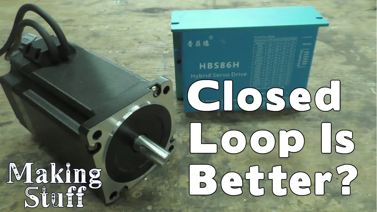
Closed Loop Stepper Motors for CNC machines
198.8K
Closed-loop stepper motors integrate encoders for bidirectional communication between motor and controller, unlike open-loop motors that lack feedback. The hybrid servo controller processes encoder signals to verify step completion, correcting missed steps and triggering alarms when limits are reached. This architecture provides automatic error detection, position correction, and enhanced safety features not available in standard open-loop systems used in 3D printing and hobby CNC applications.
Click to watch →

MKS SERVO42C Closed-Loop Stepper: Tests vs Servo with Field-Oriented Control and TMC2209 Open-Loop
184.2K
This video compares three motion control systems—MKS SERVO42C closed-loop stepper, generic NEMA17 open-loop stepper with TMC2209 driver, and a custom servo system—through thermal, acceleration, and speed tests. The results show that while closed-loop steppers offer quiet, energy-efficient operation suitable for applications like camera dollies and timelapse sliders, they perform poorly in acceleration and speed tests compared to both the open-loop stepper and the servo. The open-loop stepper provides a simple, low-cost solution but wastes power when stationary and cannot match servo speeds. The servo system delivers the highest performance in terms of speed and acceleration but requires complex control loop tuning. Each system has distinct advantages depending on the application requirements.
Click to watch →
Deep Dive
Familiarity with the Klipper 3D printer firmware architecture, configuration files, and how it manages multi-MCU (microcontroller unit) setups.

Klipper 3D Printer Firmware Install - How To - Chris's Basement
120.8K
Klipper is a 3D printer firmware that offloads processing to a Raspberry Pi, enabling faster printing speeds compared to traditional firmware like Marlin. The installation process involves cloning Klipper from GitHub, running the install_octopi script, configuring build settings via make menuconfig, compiling the firmware, and flashing it to the printer's mainboard. Configuration requires setting up stepper motors with step distances (distance per step in mm), configuring endstops with pull-up resistors and logic inversion, setting up probes with virtual endstops, configuring mesh bed leveling with probe points, and creating G-code macros for bed leveling. The OctoPrint interface connects to Klipper through a serial port at /tmp/printer with a baud rate of 250,000. Troubleshooting involves stopping the Klipper service, unplugging the USB, restarting the printer, and reconnecting to resolve configuration errors.
Click to watch →

Klipper Explained – Ep. 1: Why It’s Different
9K
Klipper is an advanced open-source 3D printer firmware that operates using a host-microcontroller architecture, where a powerful host device (such as a Raspberry Pi) handles all motion calculations and G-code processing, while the printer's microcontroller executes pre-processed commands. This architecture enables advanced features like Pressure Advance and Input Shaping that compensate for pressure changes and mechanical vibrations, allowing printers to achieve higher speeds and better print quality. Unlike traditional firmwares like Marlin and RepRapFirmware that run entirely on the printer's microcontroller, Klipper's host-based approach provides faster processing, better touchscreen support, and the ability to run multiple printers simultaneously. The host software is written in Python and runs as a Linux package, with configuration files stored on the host for easy modification without firmware reflash.
Click to watch →
Самый Бездарный Гайд По Установке Klipper
24.6K
Installing Klipper firmware on a 3D printer requires a single-board computer (like Raspberry Pi or Orange Pi), proper power supply with voltage regulation, and careful configuration of the printer's MCU connection; the process involves flashing the OS to the SBC, flashing the printer's microcontroller, and configuring the printer.cfg file, with common issues including power instability causing connection loss and the need for input shaping calibration using an accelerometer for optimal print quality.
Click to watch →

Klipper - Mainsail - Fluidd - 2022 - Chris's Basement
94.7K
This section covers the complete workflow for configuring Klipper after firmware installation. It begins with verifying the serial connection using 'ls /dev/serial/by-id' and obtaining the complete device address for the printer.cfg file. The video demonstrates creating printer.cfg by copying example configurations from the Klipper config directory or Mainsail interface, replacing the mcu serial line with the actual device address, and including UI-specific configuration files (mainsail.cfg or fluidd.cfg) to enable dashboard features. It covers troubleshooting Moonraker permission errors using policykit scripts and demonstrates webcam integration using MJPEG streamer. The section concludes by explaining that both Mainsail and Fluidd are actively developed with similar feature sets, making the choice primarily a matter of user preference.
Click to watch →
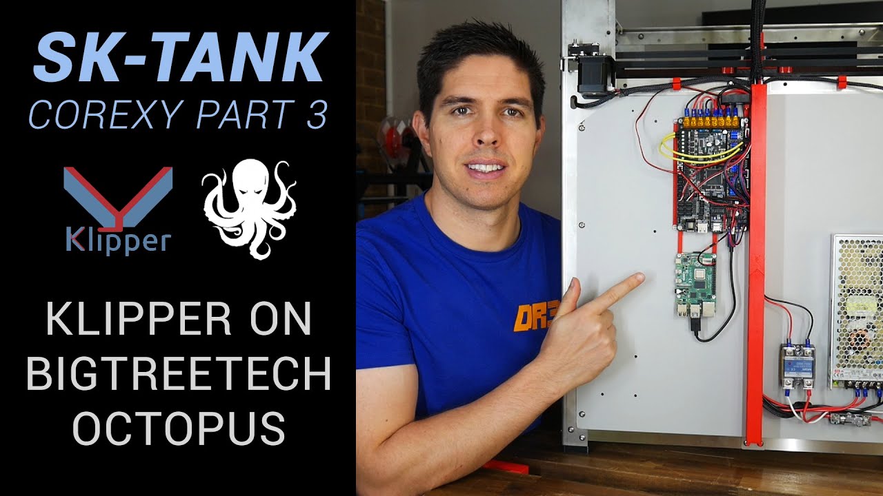
SecKit SK-Tank coreXY build pt 3 - Wiring and Klipper firmware on BTT Octopus
54K
Setting up Klipper involves installing Mainsail web interface on Raspberry Pi using the Imaging Tool, then creating a blank configuration and adapting existing configurations from similar boards. Pin mappings must be updated using the official pin diagram, and driver settings (TMC2208 vs TMC2209) must be adjusted. After configuring printer.cfg, firmware is compiled using mcu command in Putty, retrieved via WinSCP, renamed to firmware.bin, and flashed to the Octopus SD card. A common issue is connection failure between Pi and MCU, resolved by changing the serial port. The configuration checks page verifies thermistors, heaters, emergency stop, steppers, and end stops, then performs PID tuning. Z-tilt compensation uses three bed mounting points and three probing points to calculate height differences and apply real-time corrections, ensuring the bed is parallel to the XY plane of motion.
Click to watch →
Deep Dive
Basic microcontroller programming and hardware interfacing concepts, specifically involving the ESP32 and Raspberry Pi Pico (Pico 2) platforms.

Raspberry Pi Pico Full Guide 🔥 | Beginner to Pro Tutorial
10.4K
MicroPython uses familiar Python syntax for microcontroller programming. Import the machine library to create pin objects: led = machine.Pin(25, machine.Pin.OUT). Control LEDs using led.value(1) or led.on(), and led.value(0) or led.off(). Implement blinking with while True: led.on(); led.off() combined with time.sleep(0.5) for visible effects. Understand breadboard connections where columns share electricity and middle strips separate sections.
Click to watch →
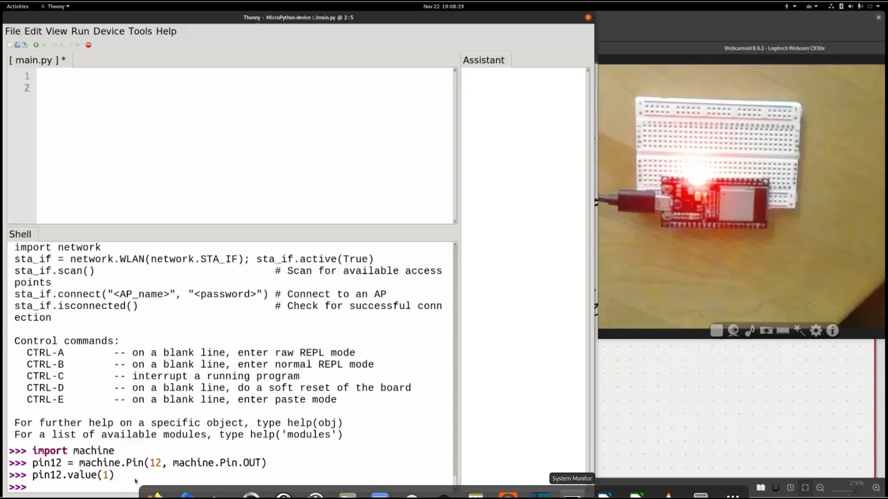
ESP32 Mikrocontroller Programmierung, Eine erste Einführung
19.7K
This tutorial introduces programming the ESP32 microcontroller using MicroPython and the Thonny IDE, covering essential steps including flashing firmware, setting up the development environment, connecting hardware components like LEDs, and controlling GPIO pins to create a blinking LED program that demonstrates basic hardware interaction.
Click to watch →

Raspberry Pi Pico - Getting Started with MicroPython with Thonny and rShell
31K
This section covers essential MicroPython programming concepts and hardware control on the Raspberry Pi Pico. Key topics include importing modules like machine and time, controlling the onboard LED connected to GPIO pin 25 using Pin.OUT and toggle() methods, and implementing time delays with time.sleep(). The tutorial demonstrates creating variables, performing arithmetic operations, and printing formatted output to the console. A critical concept is saving code as 'main.py' for automatic execution upon boot. The video also explains the file system architecture, distinguishing between the 128MB mass storage and 2MB onboard flash memory where code is stored.
Click to watch →
![Raspberry Pi PICO: Le petit nouveau de la framboise | Revue et Test [FR]](https://i.ytimg.com/vi/JINPW72kq9s/maxresdefault.jpg)
Raspberry Pi PICO: Le petit nouveau de la framboise | Revue et Test [FR]
7.2K
The RP2040 supports C++ and MicroPython programming. For C++, install make and Git, clone the Pico SDK and examples repositories, use 'make' to compile, and program via UF2 file by holding BOOTSEL button while connecting. For MicroPython, hold BOOTSEL while connecting to create a virtual drive, download the MicroPython UF2 file, and use Thonny IDE with the Pico plugin for development. LED control uses machine.pin module with GPIO 25 as output. The board lacks Arduino compatibility but will be addressed with the upcoming Arduino Nano RP2040.
Click to watch →

MICROPYTHON ON ESP32
69.1K
This tutorial demonstrates how to program the ESP32 microcontroller using MicroPython, covering the complete setup process including installing Python and Thonny IDE, downloading and uploading the MicroPython firmware via ESP Tool, and writing Python code to control hardware features like the onboard LED using the machine module's Pin class.
Click to watch →
Deep Dive
Fundamental concepts of serial communication protocols (such as UART, SPI, and I2C) used for inter-chip and host-to-MCU communication.

Serial Protocol Fundamentals
29.1K
Serial transmission sends data one bit at a time over a shared bus, offering advantages over parallel transmission including longer distances, higher throughput, and support for more nodes; three common low-speed serial protocols are UART (asynchronous, two-wire, uses start/stop bits and optional parity for framing data), I2C (synchronous, two-wire, master-slave architecture with address-based communication and acknowledgment bits), and SPI (synchronous, four-wire, full-duplex with separate chip select lines for addressing slaves); each protocol defines how bits are formatted into messages and the rules for exchanging data between devices.
Click to watch →

PROTOCOLS: UART - I2C - SPI - Serial communications #001
1.6M
This video explains three fundamental serial communication protocols used in microcontroller applications: UART (Universal Asynchronous Receiver Transmitter) uses two wires (TX/RX) with start/stop bits and a shared clock, requiring configuration of baud rate and data format; I2C (Inter-Integrated Circuit) uses two wires (SDA/SCL) with a clock line for synchronization and slave addressing, allowing multiple devices on one bus; SPI (Serial Peripheral Interface) uses four wires (MOSI/MISO/SCK/CS) for full-duplex communication without slave addressing, offering higher speed and lower power consumption but limited range. Each protocol balances trade-offs between connection count, speed, complexity, and range.
Click to watch →

Protocols : UART | SPI | I2C | Embedded Systems Communication Protocols
15.7K
This video explains three fundamental communication protocols used in embedded systems: UART (Universal Asynchronous Receiver/Transmitter) uses two wires for one-to-one master-slave communication with a frame format including start bits, data bits, parity bits, and stop bits, achieving speeds up to 5 Mbps; SPI (Serial Peripheral Interface) is a four-wire protocol supporting one master with multiple slaves using MOSI, MISO, SCLK, and SS pins, capable of full-duplex communication at speeds up to 60 Mbps; I2C (Inter-Integrated Circuit) is a two-wire multi-master/multi-slave protocol invented by Philips in 1982, supporting up to 128 devices with 7-bit addressing and built-in acknowledgment bits, achieving speeds up to 3.4 Mbps. Each protocol has distinct advantages and trade-offs in terms of speed, complexity, and application suitability.
Click to watch →
Embedded Systems Protocols Serial-UART I2C SPI Communication
70.3K
This webinar explores three essential serial communication protocols used in embedded systems: UART (Universal Asynchronous Receiver Transmitter) for basic microcontroller-to-computer or sensor communication using TX/RX pins; I2C (Inter-Integrated Circuit) for multi-device communication over two wires (SDA/SCL) with unique slave addresses, commonly used for sensors and memories; and SPI (Serial Peripheral Interface) for high-speed full-duplex communication using four wires (MOSI/MISO/SS/SCK), ideal for displays and memory devices. The presenter emphasizes that understanding these protocols is fundamental for embedded systems development, as they enable microcontrollers to communicate with sensors, displays, and other peripherals in industrial applications like PLCs, CNC machines, and IoT devices.
Click to watch →
EECS 373 - Fall 2025 - Lecture 16: "Exam 2 Review"
160
UART is an asynchronous serial protocol requiring devices to agree on a baud rate beforehand. The receiver uses oversampling (8-16x) to detect start bits and recover clock timing. UART uses separate TX and RX lines - TX connects to RX on the receiving device. SPI uses synchronous communication with a shared clock line and chip select (CS) for bus arbitration. Only the selected peripheral drives data lines; unselected peripherals go to high-impedance state. SPI supports four modes determined by clock polarity (CPOL) and phase (CPHA), allowing different peripherals to use different modes. I2C uses only two wires (SDA and SCL) with open-drain architecture requiring pull-up resistors. Communication begins with a start condition and ends with a stop condition. Each byte is followed by an ACK/NACK bit for confirmation.
Click to watch →
Prerequisite Knowledge
- Concept 01Understanding the differences between open-loop stepper motors and closed-loop servo systems, including the role of rotary encoder feedback.
- Concept 02Familiarity with the Klipper 3D printer firmware architecture, configuration files, and how it manages multi-MCU (microcontroller unit) setups.
- Concept 03Basic microcontroller programming and hardware interfacing concepts, specifically involving the ESP32 and Raspberry Pi Pico (Pico 2) platforms.
- Concept 04Fundamental concepts of serial communication protocols (such as UART, SPI, and I2C) used for inter-chip and host-to-MCU communication.
Subsequent Learning
- Step 01Advanced PID tuning techniques on the ESP32 to optimize motor response and minimize tracking errors under dynamic mechanical loads.
- Step 02Designing custom printed circuit boards (PCBs) to consolidate the ESP32, Pico 2, and motor driver circuitry while mitigating electromagnetic interference (EMI).
- Step 03Implementing input shaping and resonance testing algorithms within Klipper to measure the real-world performance gains of the closed-loop system.
- Step 04Scaling the closed-loop control architecture to industrial applications, such as multi-axis CNC routing or high-precision robotic arms.
Problem Setup
Build Start
System Core
Signal Path
Error Correction
Dynamic Response
Remote Tuning
Problem Setup
0:00Playing Section
- 1
Identifies common issue of stepper motors losing steps.
- 2
Frames solution as building a DIY closed-loop system.
Diminishing Returns and Complexity of DIY Closed-Loop Systems vs. Modern Open-Loop Steppers with Input Shaping
While DIY closed-loop servo systems using ESP32 and Pico microcontrollers theoretically prevent layer shifts, they introduce significant hardware complexity, tuning difficulties, and cost for marginal real-world benefits. Modern 3D printing relies heavily on advanced open-loop stepper drivers (such as TMC2209 or TMC2240) combined with Klipper’s native software features like Input Shaping (resonance compensation) and Pressure Advance. These software solutions mitigate the primary causes of print defects (ghosting and ringing) at a fraction of the cost and complexity. Furthermore, adding intermediate microcontrollers introduces communication latency, and because Klipper’s motion planner operates on a pre-calculated trajectory, a hardware-level correction at the motor driver can desynchronize the system or mask underlying mechanical issues. For most users, high-quality open-loop steppers coupled with software calibration offer superior reliability and comparable performance without the integration overhead of DIY closed-loop electronics.
Deep Dive
Advanced PID tuning techniques on the ESP32 to optimize motor response and minimize tracking errors under dynamic mechanical loads.
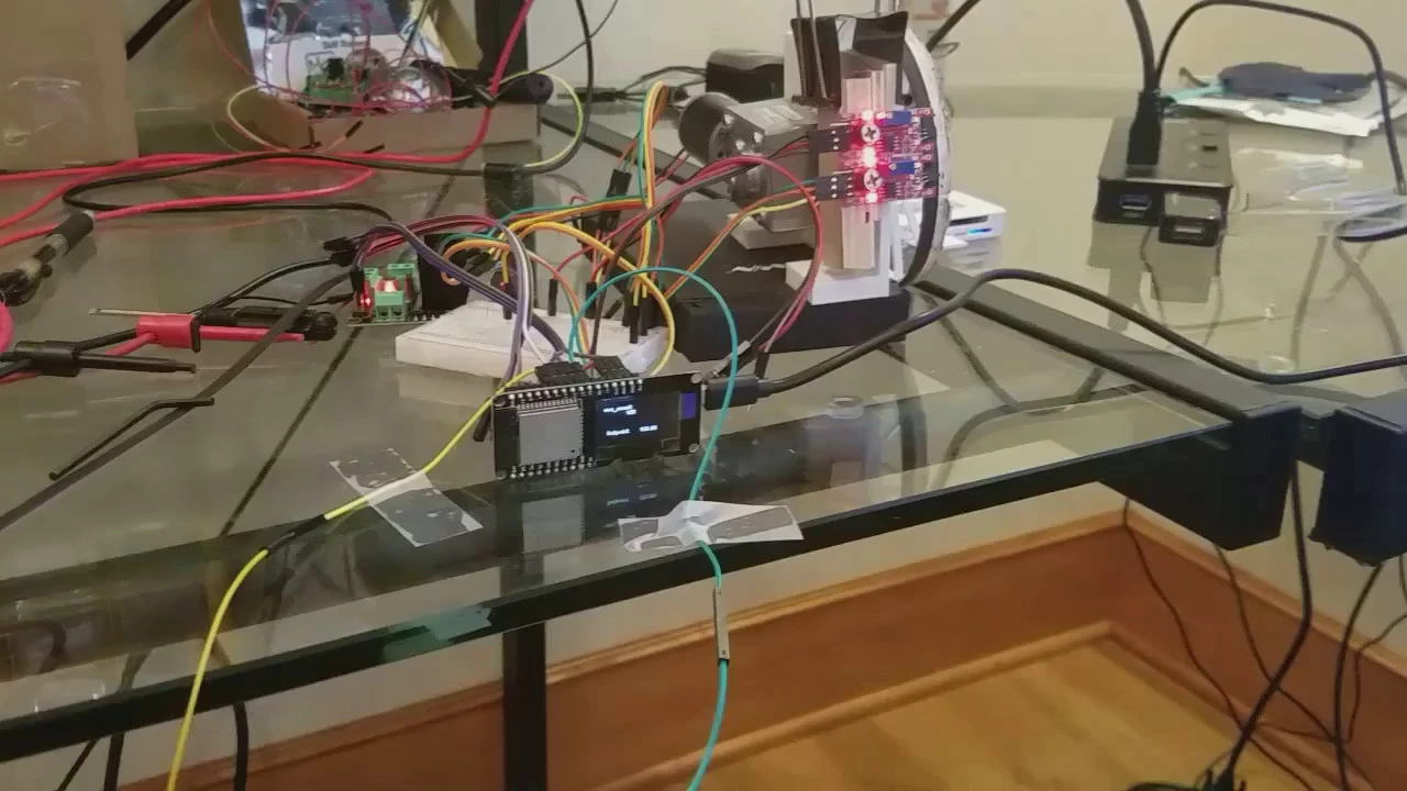
esp32 closed loop motor control hack
2.3K
This video demonstrates an ESP32-based closed-loop motor control system using PID (Proportional-Integral-Derivative) control, where touch sensors set the setpoint to ±100, and the system maintains stable control without overshooting; the presenter notes that the controller performs better with larger perturbations and has implemented distance-dependent PID tuning for improved stability, while also mentioning challenges with sensor sensitivity and power supply issues.
Click to watch →
![Controlador PID via Integral del Error 💥 [Sintonia]](https://i.ytimg.com/vi_webp/GH0sjyPOztQ/maxresdefault.webp)
Controlador PID via Integral del Error 💥 [Sintonia]
7.7K
The Integral of Error (IE) method is an optimal PID controller tuning technique that uses performance criteria (IAE or ITAE) to minimize the integral of error over a sufficiently long time period, ensuring steady-state error elimination; this method, originally proposed by López in 1957 for load disturbance rejection and extended by Rovira in 1969 for setpoint tracking, considers the entire system response curve rather than just the first quarter, making it more comprehensive than traditional methods like Ziegler-Nichols or Cohen-Coon; the method requires the system to be representable as a first-order plus dead-time model and uses optimization algorithms to determine optimal PID gains based on the system's time delay and time constant.
Click to watch →

CC and ZN tuning
7.1K
This video explains two classical PID controller tuning methods: Cohen-Coon, which uses a first-order plus deadtime process model to recommend controller parameters for achieving quarter-amplitude decay ratio, minimum integral error, and minimum offset; and Ziegler-Nichols, which determines tuning parameters experimentally by finding the ultimate gain (Ku) and ultimate period (Pu) through sustained oscillation tests, then applying empirical formulas from lookup tables. Both methods provide aggressive initial settings that may require fine-tuning using a field tuning factor.
Click to watch →

PID Tuning with the Ziegler-Nichols Method: A Tutorial
377.6K
The Ziegler-Nichols method provides two empirical approaches for determining PID controller gains: the first method uses the step response curve's inflection point to calculate L (distance from origin to tangent) and T (vertical distance), then applies formulas (KP=0.9T/L, KI=1.2T/L, KD=0.075L); the second method involves increasing proportional gain until the system exhibits sustained oscillations at critical gain Kcrit and period Pcrit, then using formulas (KP=0.5Kcrit, KI=1/(1.2Pcrit), KD=0.125Pcrit) to determine controller parameters. Both methods are simple to implement but have limitations and work best for certain transfer functions.
Click to watch →

Metode Tuning Kontroler PID
1K
This extensive section covers advanced PID tuning techniques for complex systems. It introduces Ziegler-Nichols Method 2, specifically designed for systems containing integrators (poles at the origin). Unlike Method 1, Method 2 uses closed-loop oscillation testing: apply proportional-only control and increase gain until sustained oscillations occur, recording the critical gain (Kcr) and critical period (PCR). The section provides detailed parameter calculation formulas: P-only uses KP = 0.5Kcr; PI uses KP = 0.45Kcr, TI = 0.875PCR; PID uses KP = 0.6Kcr, TI = 0.5PCR, TD = 0.125PCR. For third-order systems with integrators, the critical gain is found by setting the s-coefficient to zero in the characteristic equation, then PCR is calculated from the oscillation frequency. The section emphasizes that Method 2 is preferred when integrators are present because Method 1 cannot handle systems with poles at the origin. It demonstrates practical application through detailed examples, showing how to substitute calculated parameters into PID transfer functions to achieve approximately 25% maximum overshhoot. The section concludes by explaining how to analyze closed-loop system responses and verify that both transient and steady-state performance requirements are met.
Click to watch →
Deep Dive
Designing custom printed circuit boards (PCBs) to consolidate the ESP32, Pico 2, and motor driver circuitry while mitigating electromagnetic interference (EMI).

How to design an ESP32 PCB with KiCad (in less than 25 minutes)
156.6K
This tutorial demonstrates how to design a custom ESP32 S3 PCB using KiCad, covering schematic creation with power regulation (5V to 3.3V linear regulator), USB differential pair routing with ESD protection, decoupling capacitors, and power-on reset circuitry; the process involves converting the schematic to PCB layout, strategically placing components, routing traces with proper impedance matching for USB lines, creating ground planes, and performing design rule checks to ensure manufacturability.
Click to watch →

Mecanum Wheel Robot Car & ESP-NOW Remote
164.9K
For controlling mechanum wheels with an ESP32, you need dual H-bridge motor drivers like TB6612FNG for four motors. Power connections go to VM pins on drivers, with negative connected to ground pins. The 3.3V output powers the H-bridge VCC and standby pins (must be high to activate). Input pins connect to ESP32 GPIOs: for front module, PWMA to GP19, AI2 to GP23, AI1 to GP32, BI1 to GP33, BI2 to GP25, PWMB to GP26. Rear module uses different GPIOs. Motors connect to A01/A02 and B01/B02 outputs, noting the mirrored output arrangement.
Click to watch →

3D PRINT a STEAM TRAIN 🚂 With Steam, Live Camera Streaming & Wifi Controls
33.4K
This section covers installing the motor driver board and setting up the ESP32 microcontroller. Secure the motor driver board to the train base using M3x8 bolts, connect motor wires to the 'motor A' terminals, and swap wires if the train moves in the wrong direction. For the ESP32: upload the provided code, print the board retainer, remove protective film from the camera lens, create a slight fold in the camera's ribbon cable, secure the ESP32 so it nests against the print, hold in place with the retainer, and attach to the model using additional M3x8 bolts from underneath. This integration combines motor control electronics with wireless communication capabilities.
Click to watch →

ESP32 (Keyes) Board with VNH5019 Dual Motor Driver
2.5K
This video demonstrates how to connect a VNH5019 dual motor driver (12A per channel) to a Keyes ESP32 board using Arduino IDE, requiring connections for common ground, VDD (5V/3.3V) for logic power, and three control pins (Motor 1A, Motor 1B for direction, and PWM for speed), with the ESP32 running at 240MHz requiring LEDCAttachPin and LEDCSetup functions instead of Arduino's analogWrite for PWM control.
Click to watch →
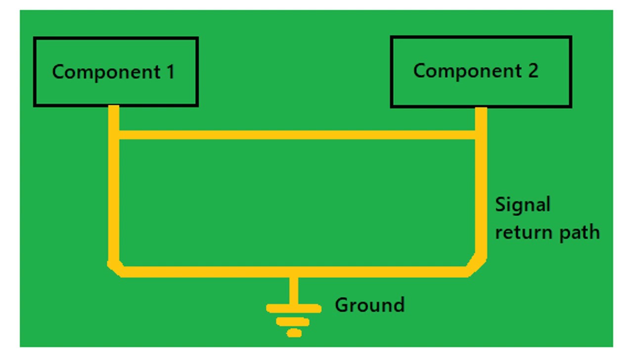
PCB Design for minimising Electromagnetic interference
13.3K
Effective PCB layout requires systematic component segregation based on functionality—grouping analog, digital, power supply, low-speed, and high-speed circuits separately with designated track areas. Filters must be used at subsystem boundaries for signals flowing between groups. Layer stack-up arrangement is critical: multi-layer boards should dedicate one complete layer as a ground plane with the adjacent layer as a power plane, ensuring the ground layer sits between high-frequency signal traces and the power plane. For two-layer boards, ground grids are recommended. Digital circuit routing demands special attention: high-speed signals and clocks require short traces adjacent to ground planes, avoiding edges and connectors. Return current follows the least reactance path, so ground traces should stay close to signal traces to minimize loop areas. Differential signals benefit from running close together for magnetic field cancellation. Clock signals require proper termination (source, parallel, or AC) to prevent reflections that cause radiation. Analog circuits need guarding with ground traces, isolation from digital sections, and low-pass filtering to reject high-frequency noise.
Click to watch →
Deep Dive
Implementing input shaping and resonance testing algorithms within Klipper to measure the real-world performance gains of the closed-loop system.
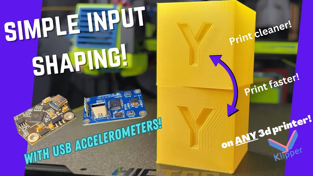
Input Shaping Made easy with a USB accelerometer!
109K
This comprehensive process covers understanding 3D printer vibration sources (movement systems, loose belts, spool holders, structural issues), identifying ghosting and ringing artifacts from high-acceleration printing, and implementing input shaping as an open-loop algorithmic control system. Klipper firmware offers five input shaper algorithms: zero-vibration (ZV/MZV) for single-frequency spikes and extra-insensitive (EI variants) for broader frequency ranges. The workflow includes configuring Klipper host devices with Python dependencies, flashing accelerometer firmware with proper wiring (RX-TX crossover, 3.3V power), creating configuration files with correct serial addresses, and mounting accelerometers using rigid or passive methods. Pre-test preparation involves measuring ambient noise and ensuring stable mounting. Resonance tests sweep frequencies from 5-133 Hz, generating vibration response graphs that determine optimal input shaper selection based on single or multiple peak patterns.
Click to watch →
![Klipper Resonance Compensation Overview - [input_shaper]](https://i.ytimg.com/vi/pH-1RWdC75E/hqdefault.jpg)
Klipper Resonance Compensation Overview - [input_shaper]
51K
Input shaper is a Klipper firmware feature that compensates for resonance/ringing in 3D printers by modifying velocity input commands during direction changes, effectively reducing oscillations that occur when printers accelerate quickly; the technique involves printing a test pattern to measure the natural resonance frequency of the printer's axes and then configuring the input shaper parameters with those frequencies to eliminate the ripple artifacts while maintaining high acceleration settings.
Click to watch →
![Klipper input shaping - A leap forward in high speed AND high quality 3D printing [Rat Rig part 4]](https://i.ytimg.com/vi/er7q-CJL1lc/maxresdefault.jpg)
Klipper input shaping - A leap forward in high speed AND high quality 3D printing [Rat Rig part 4]
443.1K
3D printer vibrations create ringing artifacts at regular intervals corresponding to the machine's resonant frequency—the natural frequency where vibrations become strongest. Input shaping addresses this by modifying stepper motor inputs to cancel vibrations, transforming the traditional speed-quality trade-off into a solvable engineering problem. The manual calibration process involves printing a ringing tower while gradually increasing acceleration, measuring oscillation distances between ghosted patterns, calculating resonant frequency using provided formulas, and selecting from six available input shaper algorithms. Accelerometer integration enables fully automated calibration, where the firmware shakes the carriage at increasing frequencies while monitoring real-time vibration feedback to identify optimal settings. Practical demonstration shows that input shaping enables dramatic speed increases without quality compromise: benchy tests showed pressure advance significantly reduced layer transition imperfections, complex model assembly at 140mm/s produced perfectly fitting parts, and decorative prints maintained exceptional surface quality. This represents a fundamental advancement in 3D printing technology.
Click to watch →
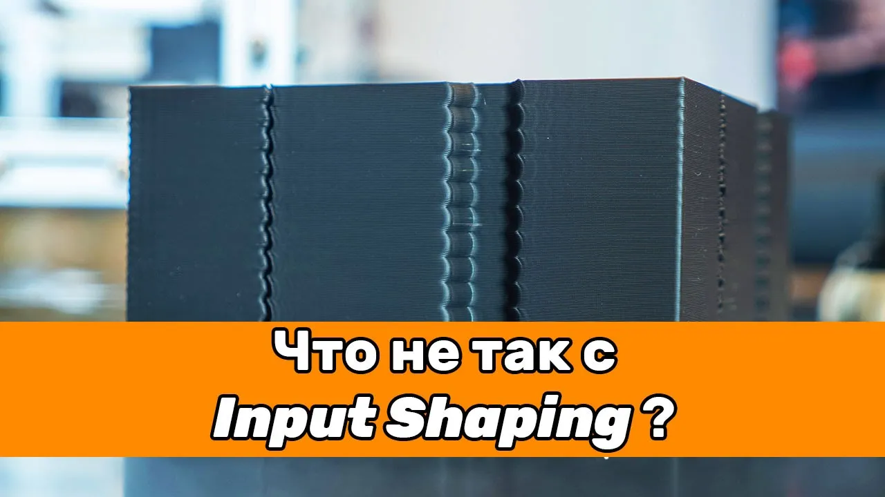
Подбор частоты Input Shaping. Что не так с методикой из документации Klipper?
66.4K
Input shaping is a Klipper algorithm that reduces echo (ringing) by counteracting print head vibrations. Automatic calibration using accelerometers fails because it only considers relative vibration amplitudes, not absolute values, leading to incorrect shaper recommendations. The Klipper documentation's manual calibration method is fundamentally flawed because it measures combined vibrations from both axes during cornering, not pure single-axis frequencies. A reliable manual method involves printing a test model with maximum settings, using Tuning Tower commands to sweep frequencies, and finding the height with minimum echo on all sides. Iterative refinement with smaller steps achieves 1-2 Hz accuracy. If MZV fails, try ZV or HAM shapers. Mechanical issues like loose components or insufficient frame stiffness may require reinforcement. PR Advance calibration is unreliable because gap size depends on material and hardware factors. Optimal print speeds should be determined empirically through testing on corner-heavy models.
Click to watch →
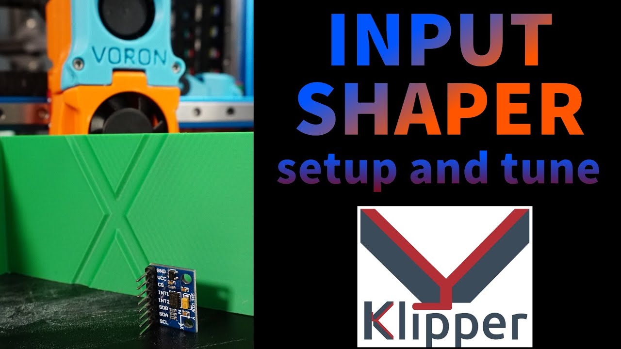
INPUT SHAPER CRASH COURSE - Print FASTER and BETTER!
290.1K
Input shaper is an open-loop control technique in Klipper firmware that reduces ringing (ghosting) in 3D prints by analyzing and canceling resonant vibrations through accelerometer measurements; the tuning process involves attaching an ADXL345 accelerometer to the printer's moving parts, running resonance tests to identify peak frequencies, and configuring input shaper parameters (shaper frequency and type) in the Klipper configuration file to enable faster printing with improved print quality.
Click to watch →
Deep Dive
Scaling the closed-loop control architecture to industrial applications, such as multi-axis CNC routing or high-precision robotic arms.

LA MECCATRONICA PER L’AUTOMAZIONE INDUSTRIALE DEGLI IMPIANTI PRODUTTIVI - JOB&Orienta 2020
2.5K
Closed-loop control systems enable automatic process regulation through continuous feedback comparison between reference inputs and actual outputs. Modern mechatronic systems utilize PLCs as central controllers, power converters scaling signals to actuators (electric, pneumatic, hydraulic), and advanced sensors including vision systems. The industrial automation pyramid stratifies functions: field level (hardware devices), control level (PLCs and field devices), supervision level (HMIs and monitoring), and enterprise level (ERP systems). Human-Machine Interfaces enable operator interaction while predictive maintenance applies data analytics for equipment health forecasting.
Click to watch →

07. 제4과목 cnc공작법 및 안전 핵심이론
12.5K
Closed Loop Control System (폐쇄회로 방식) uses a scale (scales) attached to the machine table to detect position and provide feedback. This is the key characteristic that distinguishes it from other control systems. The scale is crucial for high-precision machining operations.
Click to watch →

PLC2: Closed Loop Control
193
Industrial closed loop systems include hopper level control using level probes and Variable Frequency Drives to maintain consistent material flow rates. Robotic arms require dual closed loop control for position (joint angle) and velocity, with the controller generating errors for both and processing them to drive servo motors. These applications demonstrate how closed loop principles apply across different industries and equipment types.
Click to watch →

Centenary Celebration, Mech Engg, IIEST Shibpur, 27th Centenary Lecture, Dr. Naresh Chandra Murmu
130
Additive manufacturing systems face unique motion control challenges: standard CNC controllers cause excess material deposition at edges, may go out of CAD areas, and experience sudden jumps. Solutions include hardware modifications (safety measures, electric brakes, dynamic braking registers) and software limit configurations. Achieving dimensional accuracy requires closed-loop control systems with height sensors for real-time monitoring and feedback control loops. Industrial applications include repairing expensive turbine blades (70-75 lakhs) where small cracks would normally require complete part rejection. Powder characteristics significantly impact success: particle size (30-40 micron) and sphericity affect capture efficiency (80-90%). Smaller particles reduce energy requirements but may decrease capture efficiency as more powder is carried away from the substrate.
Click to watch →

CIM UNIDAD 4
554
Closed loop control systems are used in more sophisticated CNC machines. In this system, sensors continuously measure the actual position of the machine axes and feed this information back to the control system. The control system compares the actual position with the commanded position and makes adjustments if there is any error. This provides much higher precision, typically achieving tolerances in thousandths of a millimeter. The system can compensate for any disturbances or errors that might occur during operation.
Click to watch →
Problem Setup
Build Start
System Core
Signal Path
Error Correction
Dynamic Response
Remote Tuning
Problem Setup
0:00- 1
Identifies common issue of stepper motors losing steps.
- 2
Frames solution as building a DIY closed-loop system.
Diminishing Returns and Complexity of DIY Closed-Loop Systems vs. Modern Open-Loop Steppers with Input Shaping
While DIY closed-loop servo systems using ESP32 and Pico microcontrollers theoretically prevent layer shifts, they introduce significant hardware complexity, tuning difficulties, and cost for marginal real-world benefits. Modern 3D printing relies heavily on advanced open-loop stepper drivers (such as TMC2209 or TMC2240) combined with Klipper’s native software features like Input Shaping (resonance compensation) and Pressure Advance. These software solutions mitigate the primary causes of print defects (ghosting and ringing) at a fraction of the cost and complexity. Furthermore, adding intermediate microcontrollers introduces communication latency, and because Klipper’s motion planner operates on a pre-calculated trajectory, a hardware-level correction at the motor driver can desynchronize the system or mask underlying mechanical issues. For most users, high-quality open-loop steppers coupled with software calibration offer superior reliability and comparable performance without the integration overhead of DIY closed-loop electronics.
Understanding the differences between open-loop stepper motors and closed-loop servo systems, including the role of rotary encoder feedback.
Familiarity with the Klipper 3D printer firmware architecture, configuration files, and how it manages multi-MCU (microcontroller unit) setups.
Basic microcontroller programming and hardware interfacing concepts, specifically involving the ESP32 and Raspberry Pi Pico (Pico 2) platforms.
Fundamental concepts of serial communication protocols (such as UART, SPI, and I2C) used for inter-chip and host-to-MCU communication.
Advanced PID tuning techniques on the ESP32 to optimize motor response and minimize tracking errors under dynamic mechanical loads.
Designing custom printed circuit boards (PCBs) to consolidate the ESP32, Pico 2, and motor driver circuitry while mitigating electromagnetic interference (EMI).
Implementing input shaping and resonance testing algorithms within Klipper to measure the real-world performance gains of the closed-loop system.
Scaling the closed-loop control architecture to industrial applications, such as multi-axis CNC routing or high-precision robotic arms.
1.3K views17likes0:44@EngineeringRoboticOriginal Release: 2026-04-22
Want to make sure your 3D printer or CNC never loses a step and ruins a print again?
Let's build a DIY closed-loop stepper system. I mounted an AS5600 magnetic encoder to the back of a standard NEMA 17 stepper.
This gives us exact physical feedback of the rotor's position. The brain is an ESP32.
Clipper sends step and direction signals to a Raspberry Pi Pico, which passes them to the ESP32. The ESP32 compares the requested step to the actual physical angle.
If you bump the bed, the PID loop instantly calculates the error and sends corrected signals to the TMC motor driver to pull it right back. You can even tune the PID and adjust the current wirelessly via a custom web UI.
Full code and Clipper config are on my channel. Subscribe and give a like for more interesting videos.
Up Next

7:58
EtherCAT Motion Controller for Delta Robot Programming Guide
@ZmotionController666
315 views•2024-05-16

30:32
Ultrasonic Transducers: Resonant Frequency Measurement and Horn Design
@imajeenyus42
229.9K views•2017-02-22

54:16
Polymer Environmental Degradation: Mechanisms & Stabilization
@iit
1.8K views•2012-07-10

33:39
How a Student's Question Saved a NYC Skyscraper from Collapse
@veritasium
22.8M views•2025-04-26
Related Study Plans & Knowledge Roadmaps
Structured learning paths in Engineering
engineering
Building Acoustic Levitators: Physics & Arduino
01The Physics of Sound and Standing Waves
02Piezoelectric Transducers and H-Bridge Drivers
03Arduino Programming: Generating 40 kHz Signals
+ 2 more learning modules
14h5 modules
Explore Roadmap
engineering
Building Peltier Cloud Chambers: Particle Tracks
01Cosmic Rays & Cloud Chamber Physics
02Thermoelectric Cooling (TEC) Fundamentals
03Custom Liquid-Cooling Loop Design
+ 2 more learning modules
18h5 modules
Explore Roadmap
engineering
Yagi-Uda Antennas: Modeling, Build & VNA Test
01Introduction to RF and Antenna Fundamentals
02Yagi-Uda Antenna Design Principles
03Antenna Modeling and Simulation in 4NEC2
+ 2 more learning modules
18h5 modules
Explore Roadmap
engineering
ECG Monitor Design: Op-Amps, Filters & Noise
01Electronics & Breadboard Basics
02Op-Amps and Instrumentation Amplifiers
03Bioelectricity and ECG Fundamentals
+ 2 more learning modules
18h5 modules
Explore Roadmap