















![Intelligent Robots in 2026: Are We There Yet? [Nikita Rudin] - 760](https://i.ytimg.com/vi_webp/346Enb7CUfQ/maxresdefault.webp)


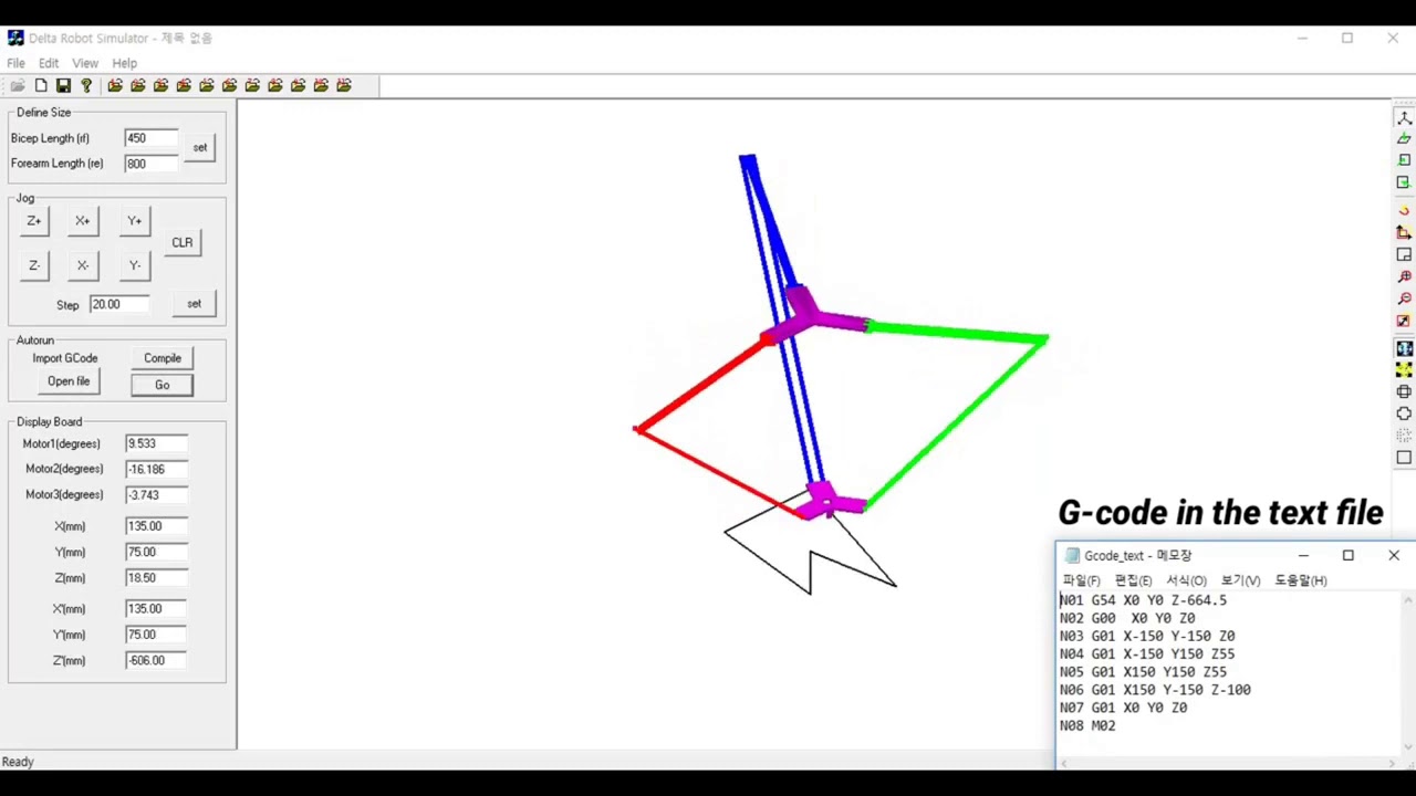
A Delta robot is a parallel chain robot with two platforms (fixed upper and moving lower) connected by three parallelogram arms that constrain the lower platform to remain parallel; its key advantages include high speed due to lightweight composite materials, making it ideal for pick-and-place operations. The direct kinematics problem involves computing elbow points from joint angles and finding the intersection of three spheres, while inverse kinematics allows independent computation of each joint angle. The workspace depends on the base platform dimensions and the ratio between lower and upper arm lengths. Differential kinematics reveals singularities occurring when links are parallel or when lower links lie in the moving platform's plane. Dynamics are analyzed using Lagrangian mechanics, yielding 24 first-order differential algebraic equations. Motion control employs decentralized PD controllers with integral action for each joint, incorporating PID control loops with saturation stages to reject disturbances from cable effects and achieve precise trajectory tracking.
Delta Robot Simulation: Kinematics, Dynamics & Control in MATLAB/Simulink
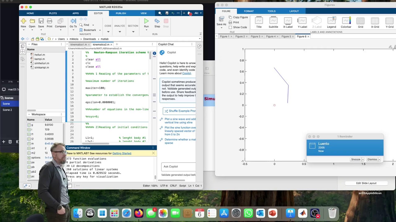
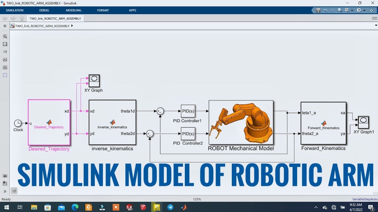
Added:[Music] hi my name is Maria Assunta madjoe and we will discuss about Delta robot and Delta robot is a parallel cross chain robot which consists of two platforms the upper one that is fixed and the moving one on which the end effector is attached the platform's are connected through three arms with parallelograms which restrain the orientation of the lower platform to be parallel to the upper one the main advantage of a delta robot is its speed since the only moving part is its frame made of lightweight composite materials due to their speed the Delta robots are widely used in pick-and-place operations of relatively lightweight object the most famous Delta robot is the black speaker every Delta robot which is shown in the following video hello my name is Teleco Casali and i will discuss about the kinematics of the data log let us start with the direct kinematics now in the three joint angles we can compute the elbow points a 1 a 2 and a 3 and since the end effector platform orientation it's always constant and horizontal we can define three steel centers like in this image and then constructing in each Center a sphere with the values equal to the lower arm length then the solution to the problem will be given by the intersection of the three scales as we can see here there are two possible solutions but the one we will choose is the one that puts the end-effector platform above the base platform so point we know the inverse kinematics this problem is easier than the previous one because we can obtain each joint angle independently from the others and the solution is given by the intersection between acetal located where the joint is and a sphere located in the platform as we can see there are two possible solutions but we choose the one with the elbow King kadhal instead of kicked in the region described by the original of the end-effector frame when all joints execute all possible motions it's called the workspace here is an example of the workplace for a given dimension of the Delta it depends mostly on the dimension of the best platform and on the ratio between the lower and the approach he wente is the best platform we can see that there are something once this becomes smaller and we decrease it will be bigger and the ratio between the lower and the upper arm will define the height and the width of the workplace hi I'm Otto Salinas and I will briefly explain the differential kinematics of the data robot this can be analyzed from the first derivative of the three position constant equations of the robot and their resulting matrices nevertheless these are very complex to derive any conclusion on where singularities may arise therefore the differential kinematics can be also studied by analyzing the system with these different frames in this case all represents the of the fixed based capital L is the upper link lowercase L is the lower link and these are the joint variables theta 1 theta 2 I Antikythera in order to arrive to the Jacobian matrix this loop equation is analyzed in dr. mathematical calculations we arrive to this equation and then to the Jacobian matrices in this way it is possible to identify the singularities by analyzing the to patch accordion starting from J theta putting is a terminal equal to 0 these two conditions are found in a similar way realizing do P also these two conditions can be found the first condition corresponds to the case when the two links are parallel so when the pasture is completely stretched or retracted while the fourth condition corresponds the case when the links lower case lie in the plane of the moving platform that is actually a reachable given opposed the result Jacobian is equal to this product the product J times G transpose describes the shape and orientation of these ellipsoids they represented the velocity and the force manipul ability of the end effect it is worth noting that the distribution of the ellipses is symmetrical about three intersecting axes 120 degrees apart and these the conference the positions of the two M's my name is and recruiting and I will explain the dynamics of the Delta reward firstly we will introduce the Lagrangian it yet there are two contributions the first contribution is given by the kinetic energy and the second contribution is given by the potential energy in the first part of this analysis we will consider the Lagrangian as unconstrained so there will not be any constraint on the end effector the unconstrained Lagrangian is given by the sum of the Lagrangian for each link then we will define the so called augmented Lagrangian in which there is a contribution of the unconstrained Lagrangian plus another term the contains all the physical constraints on the end effector at the end of this analysis we will derive the dynamical equations of order Delta robot defining T dot equals to B we can derive the Lagrangian return as a set of 24 first-order differential algebraic equations now we will discuss about the motion control over Delta robot the motion contour is performed in to the joint space the joint space control problem is divided into two actions first they decide the path in the operational space has to be translated into the corresponding motion into the joint space then it's possible to track the reference by using a position feedback loop the simplest control strategy that can be used is considering the fed joins independently of the others and trying to control them separately the cable effects are considered as the disturbance for the single joint servo so this approach leads to decentralize the control structure in which each joint is controlling to negate the effects of the others in this case the controller requires good performance in terms of high disturbance rejection in order to guarantee that the actor position is a proxy but they decide one so let's assume that the motor attached to each joint is described by this transfer function in order to reject the disturbance coming from the capping effects the controller requires a large implication value and an integration a contribution to compensate the gravity effect at steady state condition so a PD controller is used for each joint to control the motion of the end effector hello my name is Tom Hogan and I will talk a little bit about the simulation of the Delta roll that we have been developing we have you see meaning as well simulation software with the help of the toolbox simply on this window it is represented the entire structure of the roll and if we focus our attention on this section we will find the ebu trajectory of the end-effector that arrives to the inverse kinematic block this block return a sample theta 1 theta 2 and theta 3 that are the joint angles of the equators for each one of these angles there is a corresponding feedback control loop where on it inside it is present a PID controller as saturation stage and a transfer function representing the DC motor clicking on the scope we will find as the few graph the angle difference follow it by the PID output it is here when it can be seen the important of the saturation of stage that prevent extreme values of voltage entering the DC motor it is serían that the output of the motor our torques that enter to the analytical model we have chosen sim scale for the dynamical simulation in order to avoid solving the 24 differential equation that we found on the dynamic analysis inside this block it is described in trial structure of the manipulator that can be automatically plot in 3d maybe a troupe of Sims game run in the simulation we found that the robot follow in ohms a perfect manner the input refectory insulating each axis the following graph can be analyzed the three of them have a transient period that disappeared quickly in time and the stage telephone has no mirror finally focusing our attention on how the angles of the actuator behaves we discover a symmetrical pattern that is due to the symmetry of the desired trajectory [Music]
Up Next
Building a 3D Printed Delta Robot with Arduino
@isaac879
114.2K views•2019-04-08

MathWorks Virtual RoboSub Simulation Environment | Webinar 2026
@RoboNationInc
209 views•2026-03-10

How to Build a Self-Balancing Robot: Arduino Nano & MPU6050
@easytechzones
16.8K views•2022-03-09

Micromouse: The Fastest Maze-Solving Robots on Earth
@veritasium
23.5M views•2023-05-24
Related Study Plans & Knowledge Roadmaps
Structured learning paths in Robotics