





![Getting Started with CMake on Windows [Ep 1.2]](https://i.ytimg.com/vi/ccDPSF4V2N8/hqdefault.jpg)









![[Updated Video: https://youtu.be/siQTCJ2t5v4] STM32 FreeRTOS Series Part 1](https://i.ytimg.com/vi_webp/muOL9SH0p9g/maxresdefault.webp)






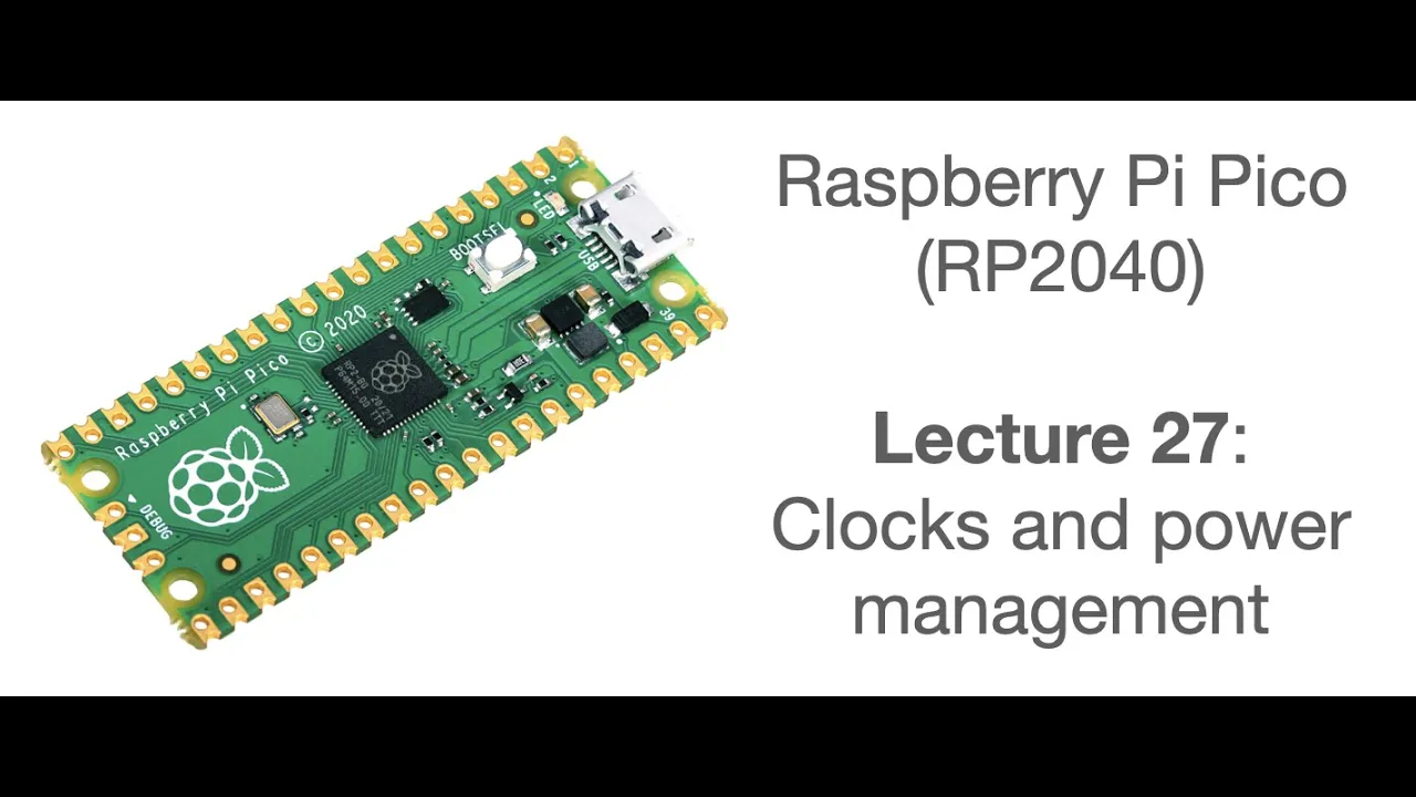


The Raspberry Pi Pico is a $4 microcontroller featuring the RP2040 dual-core Cortex-M0+ processor running at 133 MHz, with 264KB of SRAM (10x more than Arduino Uno), USB host/device capability, and unique programmable I/O (PIO) blocks that enable hardware-level protocol implementation without CPU cycles, making it ideal for embedded projects requiring custom timing or vintage computing interfaces.
Raspberry Pi Pico RP2040 Embedded Programming: C/C++ Framework Guide
Added:Fundamental proficiency in C/C++ programming, including pointers, structure definitions, and basic memory management.
Basic understanding of microcontroller architecture, including concepts like GPIO (General Purpose Input/Output), registers, and interrupts.
Familiarity with the command-line interface (CLI) and build systems, specifically CMake and the GCC compiler toolchain.
Basic knowledge of electronics principles, such as voltage, current, pull-up/pull-down resistors, and reading simple schematic diagrams.
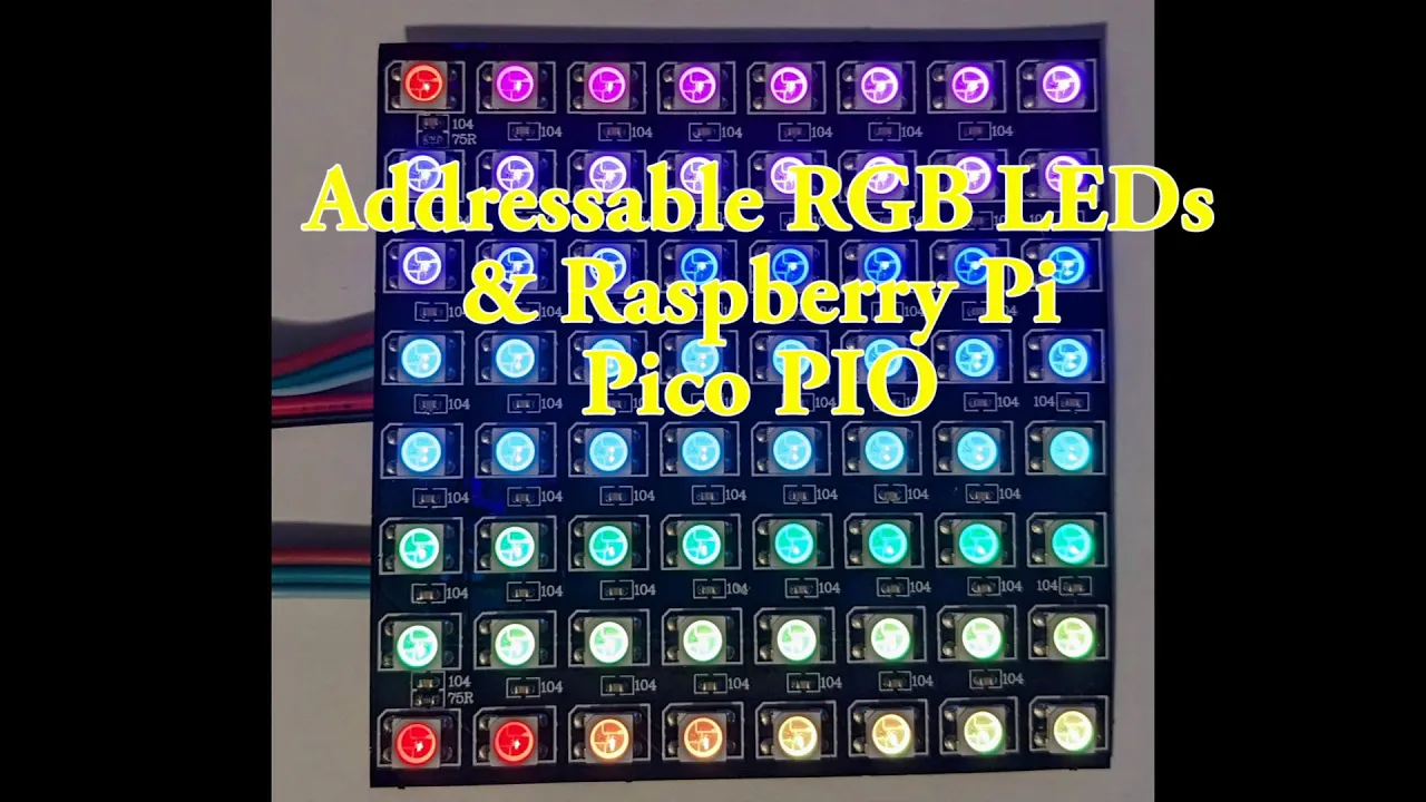
Advanced PIO (Programmable Input/Output) state machine programming to implement custom hardware protocols (e.g., WS2812B LED drivers or custom video output).
Multicore programming techniques to leverage both ARM Cortex-M0+ cores of the RP2040 simultaneously using inter-core queues and mutexes.
Integration of a Real-Time Operating System (RTOS) like FreeRTOS for managing complex multi-threaded embedded tasks.
Implementation of Direct Memory Access (DMA) to transfer data between peripherals and memory without CPU intervention.
Low-power optimization strategies, including sleep and dormant modes, to run the RP2040 efficiently on battery power.
6.5K views129likes1:25:20Original Release: 2022-02-10
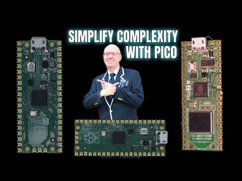
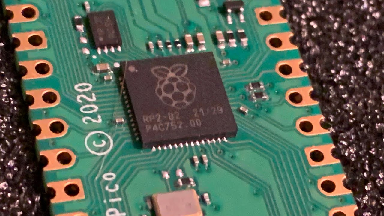
okay this month uh in our embedded winter series we will be looking at the raspberry pi pico which is a cheap four dollar microcontroller uh it's deceptive in that it's it's cheaper and smaller than the arduino uno that we looked at last month but it is much much more powerful and it has a lot more resources on chip so let's take a look first at the data sheet for the board so this is as the title of this document says an rp 2040 based microcontroller board the rp2040 is a custom cpu chip that was created by the raspberry pi foundation for embedded physical computing type applications as opposed to the raspberry pi single board computer which is a fully functioning computer with you know hdmi output and keyboard input and so on uh we'll look at the raspberry pi 4b next month but we're starting with something between the rd in terms of raspberry pi products we're starting with something in between the arduino and the raspberry pi 4. so here's what this little board looks like let me zoom in a little more for you um so in the center here is the rp2040 microcontroller uh i believe this secondary chip over here is the little uh flash memory chip that gives you extra storage there's a button there's an led and there's a usb micro usb port and you notice if you follow the circuit traces the usb port is connected directly to the cpu and that's one of the things that makes the raspberry pi pico really interesting for these physical computing applications you know an embedded microcontroller is because the usb port being connected directly to the microcontroller allows the pico to pretend to be either a host to which other usb peripherals are attached or it can be a usb peripheral attached to another host so unlike the uno which can only be a peripheral the raspberry pi pico can be a host which means if i want to i can attach a keyboard to the pico and have keyboard input to my microcontroller from a regular usb keyboard or i can attach a mouse or because of the nature of usb i can there's only one port but if i want a keyboard and a mouse and say a you know a hard drive all on usb i can attach up in the case of the pico it doesn't supply much power itself so or actually the pico itself normally i should say is not the provider of power to the system it is normally powered by usb or you can also power it by an external power supply battery or some kind of wall wart type power supply but you could plug a powered hub into the usb port and then you can have multiple usb peripherals connected to the pico but the ability for the pico to serve as a host is one of the things that makes it very different from the uno much more capable for people who've just joined you can either put questions in the chat or you can ask on audio at any time i don't mind interruptions uh the other thing that's interesting about the pico is it is uh four dollars so at the cost of four dollars you can treat these things like you know disposable handyman type things laying around in your toolbox that you just have around all the time you don't have to worry about frying one of them it's not at a big expense if you damage the board and another thing along those lines that's interesting about the board design so here's the top part of the board you can see the components are all mounted on the top they're all surface mount components the only component that has any through-hole connections is the usb connector and those connections are for physical support they're not for electrical purposes uh you can see here the bottom side of the board has no components on it at all and what's interesting about that it means that the nature of the board is such that you could treat the board as a surface mount component in another electronics project so there because there's no components on the bottom side of the board it's completely flat and the nature of the pin connections you see them around the peripheral edge of the three peripheral sides of the board here the periphery these pin connections are what is called a castellated connection so there's a through hole here that you could attach standard um 40 pin headers or sorry it's two 20 pin headers there's 40 pins along the two long dimensions uh there's three more pins here along the side which we'll talk about a little bit but along the uh edges here two 20 pin headers you could solder them onto the board and then use the raspberry pi pico as a module in a breadboard type scenario for prototyping or if you wanted to have it as a replaceable module in a system you could have a 40 pin socket that would accept the pins that you solder the header pins that you solder into the board however the other option is to treat this whole assembly as a surface mount part so these you'll notice that there's not just gold there's gold on these connector connectors but not just on the through hole part but they extend out to the side where this little half moon cutout exists and they the gold coating extends along the edge of these little half moon cutouts and contacts the underside of the board as well so that means you can take this whole module place it down on your own circuit board with suitable pads positioned to match the pin connectors of the pico and you can solder the picot down to another circuit board and treat it just like a surface mount part these types of connections are called castellated connectors or castellated pins and it allows uh for either the traditional kind of dual inline package header pins to be inserted and soldered or you can solder it directly to the surface of another board so that's an interesting thing now i mentioned that this thing is small i'm kind of you can't you don't really get a sense of scale from this document so let me show you uh camera view so here we have a raspberry pi pico and you can see it's it's only about as big as my thumb it's really small it's smaller than a stick of gum the thing next to it that's larger is an m.2 slot nvme ssd solid state disk so the little m.2 physical form factor is about the same width as the pico but it is longer so the picot itself is really not very large which is handy for things like uh if you want to do a so-called wearable project where you've got you know a piece of clothing with you know lights and maybe you know buzzers or microphones put into it so that the lights are reactive to sound and the environment so on you can have this microcontroller literally soldered to your sensors and your effectors and embedded into a piece of clothing and you're not even gonna notice it there because it's it's smaller than a stick of gum so uh if we go back here to desktop view so this is a little board and it contains this microcontroller there's obviously not much else on this board going on so whatever's going to be happening is going to be happening due to the microcontroller itself so if we look at the microcontroller data sheet similar to how we looked at the 18 mega data sheet for the arduino uno this is the microcontroller and what's interesting is that having been designed by the raspberry pi foundation there are some really interesting features of the rp 2040 that come from the specific needs of people doing little projects in the makerspace and we'll look at that in a second here so let's make this a little bigger and we'll skip over into okay here's a summary of the rp2040 it has dual cortex m0 plus processor cores running up to 133 megahertz so this data sheet just drills into the specific features of the rp2040 it does not give an exhaustive rundown of the cortex m0 instruction set which you can look at as well i mean the cortex m0 is a very well deployed microcontroller and the instruction set is very well documented and you know like another 500 page data sheet type book for the cpu so if you want to know the details of the cpu instruction set that is available to you but let's be honest most of the time as we'll see in a little bit you're going to program the pico either in micro python which is a python 3 variant or you're going to program it using the c plus sdk and so most of the time you're not going to need to know about cortex assembly language but if you want to drill down into the nitty-gritty maybe you need to write a hand-coded interrupt service routine because it has to respond within a certain number of machine cycles or something like that that instruction set is well documented you can do that it has 264k of embedded sram now if you remember from last month when we looked at the uno the uno only had like 16 or 32k of sram available so 10 times easily as much memory as the uno had it has 30 multifunction general purpose i o pins six dedicated i o pins for spi flash so the spi flash is where the long-term program memory that boots your system is going to come from right so you're going to have a flash chip that's the other chip on this little board and the the pico boots by fetching code over this spi interface to the from the flash chip to load the bootstrap code into the cpu to get the system running um it also has dedicated hardware for commonly used peripherals we'll look at what those are in a second and it has something unique to the raspberry pi pico which is these programmable i o blocks for extended peripheral support it has a four channel analog to digital converter i believe one of those four channels is dedicated to the internal temperature sensor or it's a fifth channel and the four are exposed uh to the edge of the package i can't remember which and it can operate as a usb 1.1 host or device the fact that it's usb 1.1 means you probably don't want to use this as a you know streaming video source over usb you want more bandwidth to get hd video rates over usb uh you know if you just want to do 320 by 200 yeah that's within the bandwidth of usb 1.1 but usb 1.1 is normally intended for slower peripherals things like mice keyboards joysticks things like that um the chip itself has dma so direct memory access so that means that if all you need to do is copy a chunk of memory from one location to another or to have peripheral data as it comes in off chip copied into a buffer in ram that can be done with the dma engine and doesn't need to take up cpu cycles in order to do that so in all these microcontroller based applications you want to always offload the cpu as much as possible to get the more efficient dedicated functional blocks working in cooperation with the cpu instead of having the cpu i have to do all that in a software retained cycle by cycle this ahb app bus refers to the internal connect fabric of the the pico which we'll look at here in a second so here's a block diagram of the cpu um talking to the outside world we have input pins for the clock generation of the system so i'll did all most i was going to say all digital systems but that's not necessarily true but the vast majority of digital systems digital circuits are synchronous meaning everybody is connected to a clock the same clock advances all the functional units on the circuit at a time what's nice about the pico is that it can generate clocks internally or it can have a crystal off chip and use that as the clock reference the the pico has a i believe this is a clock chip right here that is generating the system clock for the cpu you've got the swd this is the software debug port and it interacts with the cpu so that you can single step programs and so on through the swd port i mentioned that there were these three little pins on the side those are the connections for the debug port it's also possible to debug through the usb interface as a seri when a usb interface is configured as a serial port or to configure some of the gpio pins as an external asynchronous serial interface and have a debug console that way but the debug port over here lets you single step and stop and start the cpu while your peripherals are connected or when the either when the pi is acting as a host and peripherals are connected to the usb connector or when the the pico is acting as a peripheral and the host is connected to the usb connector so you've got the swd port you've got the gpio pins of which those are connected to a bunch of dedicated functional blocks which pins are being used as these dedicated functional blocks as part of the configuration state of the cpu so you can for instance choose between if you need lots of raw digital inputs or outputs into your project then you can give up using spi interface or the pwm interface or the urd interface or the i squared c interface and free those pins up for use as general purpose i o pins or if you have need for say a serial port and an i squared c port and a few digital i os then you can have the pins configured for an i squared c port have the pins configured for a uart port and then have the remaining free pins used as general purpose io uh it's also the analog to digital converter uh timers and a real-time clock and inside here is other registers that control various behavior of the cpu um but they're generally not connected to the gpio the ones that are shaded in green here are the ones that can be connected to the gpio pins there are these two green boxes over here labeled pio this is the programmable i o functional units and those are very interesting we'll talk about those in more detail later and then over here is the memory interface whether it is you know fetching the initial flash configuration from off chip or accessing the internal rom which i believe the internal rom is fixed and basically contains the lowest level boot loader that that gets the chip running uh and we'll see that there's a a couple of different modes that you can interact with the chip in order to get your code running on there and then there's that those six blocks of sram that they mentioned and the thing you will notice is there is no external bus connection so basically everything that goes in and out of this chip either comes in and out of the usb interface or it comes in and out of these gpio pins so there's no external access to the address bus of the cpu no external access to the data bus um all those address spaces and and contents are available to your code obviously which is running inside here so that implies that the code is probably loaded onto here by the usb interface which is exactly how things proceed so um here is just you know we won't go through all the details of all these pins but in order to understand how a particular gpio pin maps to the different functions they have this correlating table that lets you see like oh here this is used for pulse width modulation 3 or it's used for spi interface 0 or uar1 or i squared c1 or it's programmable io 0 or programmable io1 so just like we saw with the 18 mega chip in the uno there's a large number of internal memory mapped registers in the pico that control how all these peripherals are configured now they have a nice sdk accessible either from python micro python or accessible from c plus that raises you up out of the details of having to know all these fixed memory addresses in the address space for all these control registers so configuring things to your needs is not difficult you have a high level api for accessing that configuration but if for whatever reason you need to manipulate things directly at the hardware register level all of those register addresses and their functions and the bits and what they mean are all documented uh so if we go down here this is kind of here's another higher level view of the chip and you see that you have two cortex m0s here which is another departure from the atmega on the arduino uno which only had a single core and the atmega 328 which we looked at last time although it's not too shabby it it is a much less powerful core than in a cortex m0 so it's possible to have concurrent multiprocessing access executing on the raspberry pi pico and of course that means as you if you're going to share data or data structures you need to engage in the necessary you know mutual exclusion locking whatever you whatever algorithm you come up with maybe you use a so-called lockless algorithm to be able to exchange data between the two cores but the two cores see the same address space so both the cores and the dma engine are connected to this crossbar and the crossbar allows any of these units that have a black arrow connecting to the crossbar because it's a crossbar switch you can have core zero accessing say sram zero core one could be accessing sram 2 and the dma engine could be accessing sram 1 and because it's a crossbar they're all connected without having to contend for access between each other so this four to ten is showing you that you can have um four simultaneous connections to any one of the ten things that are left over so that means a read write connection for core zero a read write connection for core one and read and write for the dma so the dma could be reading from one sram block and writing to a different sram block and both of those dma transfers could take place in parallel without contention for the peripheral blocks on the chip they're either attached by a fast path over here that's usb or the pio blocks that go through this ahb light splitter so within here the flash the pio the two pio blocks and the usb and um some control from the dma controller they can tend for a single port into the crossbar the slower peripherals such as the uarts the spy interfaces the i squared c interfaces the adc the pulse width modulating the timer the watchdog time of the real time clock whatever other peripherals those are all sharing a single connection through this app bridge the details of all these connections and everything are all in this data sheet for the rp 2040 that we're looking at now uh so these are just kind of the high level view the details of exactly how all this stuff works is documented in here but what's really interesting in terms of the pico again are these pio units so let's look at them in detail next um that well let's take a look actually at so here's the address map of where the various pieces of the system are located in the physical address space uh we can you know some features of the core cortex m0 it's basically a nice controller for or a nice cpu for embedded projects because it has the ability to operate in lower power modes or go to sleep until an interrupt occurs something like that so that's always good to have in a battery powered project you don't want to be chewing up your battery doing nothing it has a dma controller it has rom and ram mapped into the address space i'm looking for the pio all right it's got its own chapter okay so what makes these pio blocks really interesting on the pico is you can have four state machines running concurrently there's two state machines per pio block and those state machines can talk to a fifo for receiving data or sending data so two fifos a receive fifo and a transmit fifo fifo is a first in first out buffer it's a hardware component that allows you to balance um the different rates at which different blocks consume or produce data so it's kind of like a little bit of a pipelining element that allows you to overlap execution and kind of hide latency in the pipelining if you've studied any cpu design then what i just described will sound familiar to you because it's a general trade-off between pipelining in a cpu pipelining versus latency that's one of the tricks they have to make cpus appear like they're running really fast when they're not but each state machine has access to a receive and ascend fifo and what's really interesting is the state machines can be configured to talk directly to the gpio pins they can either send signals out on those pins or they can receive signals in and between all four state machines there's a small 32 32-word instruction memory that holds a little program that describes the behavior of the state machines so why is this really interesting well you might have heard on other microcontrollers people talk about doing bit banging of a protocol or bit banging the vga display and what they're talking about there is using the cpu just plain old cpu software instructions to put signals out or in on gpio pins that follow a standard timing diagram for some kind of interface so i squared c spi these are just protocols that define how digital signals change over time in order to communicate between two chips in the case of of spi and i squared c those interfaces are designed for two chips to talk to each other so it's either a sensor chip talking to a microcontroller or a microcontroller talking to a display whatever now it's certainly feasible to do that the downside is that you have to dedicate cpu cycles to maintain the timing of those signal transmissions they're not arbitrary they you know in a lot of those systems the signals have to change within a specified amount of time and if they don't change in time then it violates the timing diagram of the interface and things don't work so the downside of bit banging although it's inexpensive you don't need dedicated hardware it's also not high performance and whatever whenever you're bit banging that protocol to another chip or to some peripheral whatever you can't be doing anything else with the cpu and the maximum rate at which you can communicate using those protocols is obviously limited by the maximum rate at which your cpu can execute instructions so with the arduino uno with the atmega328 it's possible to bang these interfaces but they won't be high performance interfaces and the uno has just enough processing power to let you bang the interface out and not much else and it can do a low res vga display style interface a vga display interface really just means you have to supply color data at a certain rate and then you have to control the horizontal and the vertical refresh of the display by periodically pulsing a horizontal sync signal to indicate that the display should move the electron beam back to the beginning of the scan line and then after displaying a certain number of scan lines in that fashion then you have to pulse a vertical sync signal to tell the display that it should now move the electron beam back to the top of the display and you do that over and over and over again to keep displaying a continuous image now you can certainly bang that out on a microcontroller and the faster the microcontroller can do it then the higher the resolution of the vga display you can generate once things get to a higher resolution like 1280 by 1024 it which is certainly you know i think they call it like svga or i can't man they kept coming up with different vj acronyms as the resolutions increased but the higher the resolution of the display that you're trying to generate the faster your cpu has to run and at a certain point it tops out and you can't generate a display any faster by bit banging and usually it doesn't top out at 1280 by 1k it tops out at much lower so these little state machines you might think 32 words of instructions is not very much but the vga interface for instance is not very complicated so you can use these state machines to get pixel data from ram comes through the fifo the state machine processes that into signals on the gpio outputs and those signals generate the input to a vga display and by coordinating the state machines together you can have the ability to track where you are which pixel you are within a horizontal scan line and which horizontal scan line you are within the frame that controls when you should generate the horizontal and vertical sync signals and all of that can be done without taking up any cpu cycles at all and the reason for that is because these fifos can be fed by dma so the dma engine which has its own discrete connection to the crossbar can be fetching the pixel data from memory sending it on demand into these pio blocks into their input fifos and then the state machine processes it to generate the necessary signals for a vga interface now you may be aware that hdmi which is the more commonly used interface now for video unlike vga vga is an analog interface so technically speaking from the gpio outputs he probably would send the digital outputs of the raspberry pi pico into a little resistor ladder to get a simple d2a conversion to get an analog voltage value indicating the red green or blue intensity of a pixel as it goes out to the monitor but hdmi is a pure digital interface where the pixel stream is supplied directly to the monitor as a digital input and then it's the monitor that takes the pixel stream of digital data and converts that into some kind of analog signal on its display and that's a more complicated protocol things have to be packed into frames and the frames have to have a certain amount of data in them so on the hdmi specification goes into the full detail of the timing diagram of that interface but the pico at four dollars has enough power in these state machines to drive an hdmi interface correctly with all the right data at all the right time not using any cpu cycles and that gets to be really interesting capability for a four dollar microcontroller so these um pio blocks because these state machines are arbitrarily programmable granted you only have 32 instructions but it turns out that the state machine programs are not that complicated so 32 instructions is usually plenty can be used to implement arbitrary communication protocols through your gpio pins so suppose you have to talk to some peripheral that has its own weird timing or is some kind of sensor that has its own weird um communication protocol that you need to adhere to and it's not spi and it's not i squared c so you can't just use those ready-made functional blocks for that you can use the pio blocks in the raspberry pi pico to control that and an example of an interface that you might need to do that suppose you have to talk to an older machine that's got a scuzzy interface the so-called small computer system interface it's a it's a parallel data interface but the control sequencing of the control signals has its own communication protocol that you'd have to adhere out adhere to and programming the control signals through the pio would certainly be easy and if it's um 8 or 16 bit wide scuzzy you have certainly have enough pins left over that you could also do the data transfer through the the pio as well so the the pio blocks are one of the more unique and interesting features of the pico but i think that's all we need to do in terms of overview of the hardware i mean we have um usb it can operate either as a host or a device you have uarts and you know the uarts are programmable to have either five six seven or eight bits of data one or two stop bits uh can have a programmable baud rate generator etc uh you've got your i squared c interfaces uh spi interfaces pulse width modulation so pulse as we discussed last month pulse width modulation allows you to take a digital output and toggle it between on and off at a certain ratio of on pulses versus off pulses and when that signal is averaged together as an analog voltage it gives you the ability to have a varying analog voltage between power and ground the power rail on the pico is 3.3 volts so if you need excuse me if you need higher voltages then you need some kind of amplifier stage afterwards but uh it has onboard timers as a watchdog timer where if the watchdog timer is on then it has to be reset periodically to indicate that the system is functioning properly and if the system gets stuck in an infinite loop and then the watchdog timer will expire by reaching zero and then it will reset the system you have a real-time clock analog to digital converters and a temperature sensor and then the synchronous serial interface is the interface used to get the flash initial bootstrap code off of the flash wrong or flash memory and into the cpu so let's take a look at the board and see how we start this up okay so get this out of the way we don't need to see that anymore um the board's really interesting it has this little button it's too close to the camera there has this little button here it's really tiny compared to my fingers isn't it and when you connect usb if you hold the button down and then connect it in and what you can't see yet is oops let's get this back okay let's go off the camera and back to the desktop and on my machine when i held the button down and connected it by usb the first thing it does is presents itself as a when amp wants to control all my flash drives for playing music anyway what it gives you is a storage device and there's this little info uf2.txt and let's just make this a little bigger and what it shows you is is the version of the bootloader so that bootloader is the stuff that's in the the flash memory that's on the board it's a raspberry pi raspberry pi pico2 and this is the board id if those things change and you notice it says info uf2 so uf2 is a file format that lets you program the pico by just dropping a uf2 file into this little drive and once you do that it re it notices that you put the file there and then it reboots and it's running the uf2 code that you put there so when you go to the raspberry pi pico website you can get a uf2 file from micro python so if we just take that and drag it over here and copy it onto the pico it'll copy over the pico disconnects the storage drive usb device from your host computer so that's why the window disappeared and now it's running the micro python interpreter because it rebooted to run that code on that uf2 file so once we've got that the question is where do we go next and i will show you there is a little micro python ide called foni so if we launch thani you'll notice down here uh in the bottom it says running micro python and then it says raspberry pi pico and in this little shell window we see that i'm connected to a python interpreter and it says it's running on the pico so how did it how is it doing that well fanny understands that once micro python has been started on the raspberry pi pico it then having removed the storage device that it was exposing to the host computer the place where we dropped the uf2 file it replaces that storage device with a com device a serial port a com port and so this ide understands that and it is now exposing to me the python read eval print loop running on the pico i mean this is just a plain old python window here i can you know you know print hello world nothing too exciting there but let's see if my program is still on there what you can do is create python scripts save them on the pico and then load them back in from the pico into this ide oh and here's my little blank script that i wrote earlier so i mentioned that they have a good sdk for programming the pico in micro python and from that sdk i'm importing machine and u-time and i'm creating an led object that represents a pin on the pico it's pin 25 and i'm gonna configure that as an output pin and if you look in the documentation for the picot board they describe that pin 25 gpio pin 25 as described in the data sheet for the cpu gpio pin 25 on this board is mapped to the onboard led that's on our little four dollar microcontroller so i've got an led object that i got attached to pin 25 and i'm just going to run in an infinite loop where i'm going to turn that led on i'm going to sleep for uh 0.2 seconds so 200 milliseconds and then i'm going to turn it off and then i'm going to sleep for half a second and if i let me let's get the camera turned on let's get this a little better so if i run this from my ide you can now see that the led is blinking on the board so blink our first python micro python example the one everybody starts with just to make sure that everything is configured correctly is now running just fine it's it's you notice it's running i can click stop and then if you look at my camera view you'll see that now the led is not flashing anymore i can change these values you know instead of on for 200 milliseconds and then off for for 500 milliseconds i can change it to be on for 500 milliseconds and off for one second i can say run it uploads it to the pico and now we see that the led is still blinking but it it the timing has changed to reflect what i changed in my script so this is a good way you know to experiment and prototype with things you've got if we stop this we can go and interactively do things over here excuse me so over here i could just easily say import machine import u time led on board is machine dot pin 25 machine dot pin dot pin dot out while true led on board value 1 view time dot sleep sleep one and a half seconds led on board that value zero sleep half a second and now we can see from the inside camera that the board's now blinking again but again it's change it's blinking at a different rate i just prototyped that in the readaval print loop if i press ctrl c in the little shell window i can interrupt that i mean i was running an infinite loop right so it's just going to keep going i can also issue stop from the toolbar here and then when you issue stop it basically resets the little python interpreter start over from zero so if i you know put in led on board here it doesn't know what that is anymore because when i clicked stop it it reset the python interpreter so now all the things that i had previously defined are gone there is so we're getting my little folder going there we go uh so the i believe this is it ah that's just this little book there's this book getting started with micro python um honestly for you guys it's i'll just give you a glance through it as it's not a bad book don't get me wrong but it's it's clearly intended for let's get this display here um here we'll turn this camera off we don't need that right now um it shows you you know how to you know put the header pins into the board and you can use a little breadboard to hold things in place while you solder it which is always a good tip and you know showing you how to do basic soldering this is clearly for like somebody who's never done anything like this but at all never done any programming never done any circuit assembly uh and i'm guessing most of the people listening to this talk you've done programming before maybe you haven't done any hardware stuff so the instructions here about soldering are certainly useful but um as we go through this we could see this is to me this feels like a book for like maybe sixth or eighth graders which is not bad certainly useful in that context but i just mentioned that because it might be a little bit too slow going for somebody who makes a living at writing software but we do have a reference manual for the python sdk and this is where you probably will want to go in order to get the names of the modules that you import and what the functions are and how they work and what they do and so on and you see in here that there's even pio support let's make this a little bigger pwm and that's my place here uh okay let me just further down the page the pio blocks are accessed directly accessible to you from python and what you can do is use a little annotation to indicate that you are writing a python function that represents pio assembly and these little these lines here represent the individual instructions the individual pio instructions and this annotation over here this bracket 31 bracket that that's explained in the details of the pio if you're going to use the pio blocks currently the only way to program them is through pio assembly but you can only have a maximum of 32 instructions across all four state machines and the instruction set is fairly small so it's not hard to to learn what this annotation is really meaning and you notice that there's no ops in here and that's in order to have the state machines operate within the appropriate timing for the protocol that you're implementing um you notice down here where they instantiate the state machine they're referencing the function that has the pio assembly information and then there's the frequency at which the state machine runs and i didn't mention this earlier but the state machines can operate at a frequency that's independent of the system clock so the state machines can be operating at the frequency that makes sense for them and the cpu can be operating at a frequency that makes sense for the cpu and that's why we had those fifo blocks between the pios and the interconnect fabric is to balance that data rate in and out because they can have different clocks but um so this document here describes all the facilities available to you in python and there's a similar document that describes how to access everything from c or c plus plus the c plus compiler that's used is a modern uh gcc port and uh actually let's go over here uh and what i wanted to show you was i guess i didn't but save the bookmark to that page but if you go to the raspberry pi pico documentation that's online at the raspberry pi foundation let's just see if we can find it real quick uh it's berry pie pico okay i think i wanted no that's a different website um i've lost track of exactly where it is i think we can drill in through here okay one of these there's a page in here oh let's try this it's one of the they're getting started so normally what they tell you to do is it's kind of linux oriented so they're telling you to you know run wget and then run pico setup that sah blah blah blah it's like well okay that's cool but what if i'm operating on a windows machine and i don't have you know all those unix utilities i'm trying to see if it's in this pdf there's a i wish i had saved the window there's a link on their website that has a set of instructions for doing it on windows a equivalent to that setup.sh let's try pico windows setup it's on github here it is so that link on the raspberry pi pico documentation site it just takes you to here to say download the latest release of the pico setup for windows and this is what i did i downloaded this pico setup windows 034 the x64 version and that's what i've got here and when you run that it will install or ask you to install all the necessary components that you need now if you're like me you already got visual studio on your machine you already got cmake on your machine uh you probably have python 3 if you if you want to build the documentation you can have doxygen installed but normally it's just like we just want to build and run right that's what we want to do so what i did is i ran that installer and since i already had visual studio i already had an ide for editing so i didn't need visual code visual studio code which is the ide that they will install for you let's make this a little bigger the ide that they will install for you i already had c make i have a modern version of cmake so i don't need cmake this build tools for visual studio 2019 that is getting you things like the microsoft compiler and make the microsoft version of the make utility and it's getting you a linker and so on what now if you're if you're targeting the raspberry pi pico you might say why do i need the microsoft compiler for windows and the answer is there are certain parts of the raspberry pi pico sdk build that run code at build time to generate files that are then cross compiled to go over to the target architecture which is the raspberry pi pico rp2040 so that's why you need the build tools for visual studio 2019. this is just the compiler it's not the ide it's the smallest chunk that you can get that will allow this all to work but i already have visual studio installed so i already have the build tools installed so i don't need to download that myself and i also have python 3 downloaded and installed so i don't need that i also have get for windows downloaded installed so i don't need that i'm not going to build the documentation so i don't need doxygen or graphviz uh zotig i'll be honest i didn't research that and find out what it was but i i didn't end up needing it but i do want the gnu arm embedded tool chain that's the cross compiler it's gcc configured to generate code for the arm cortex m0 plus i believe it can also target other arm architecture variants but we need to have it target target the cortex m0 plus because that's what's on the pi pico and it has the linker and everything else that you need in order to create a file that we can a linked version of the executable so that describes where everything goes in memory remember because this is not a virtual machine it's not a virtualized environment not a virtualized address space so when you assemble your code it actually has physical addresses for all the the code locations and data locations in your in your software so we need that and the i mentioned that there were things that ran at build time that the build tools do one of the things that happens is the output from the gnu compiler is an elf binary file so that's a executable code file in elf format elf is the typical format for linux cough co ff and pe 32 are the formats that are used on windows so we get our code compiled and linked and we get an elf file but an elf file is not a uf2 file that we can drop into the flash or the storage device that the pico shows to us when we hold the boot loader button down and plug in the power so one of the things that happens at build time through the magic of cmake is they compile a utility that converts an elf file into a uf2 file and then after they've compiled and linked the elf file for a target they convert or make a uf2 version of the elf file and that's all done through cmake stuff now what's really nice at least what i thought was really nice is uh once i ran that uh windows pico setup windows 034 x64 xe i ran that little installer and what you get is a little environment here where you get some useful scripts that help you do development on the pico so you get this pico env command file and that's similar to the visual studio batch file like vc virus all dot bat this pico emv will set up the necessary environment variables so that when you do a build it can find the gcc cross compiling tool chain it can find the pico sdk you can find all that stuff when you run this installer it gives you some of these scripts and these directories here pico examples pico extras pico playground pico sdk those all come from github and at the end of the installer it asks you if you want to clone the pico sdk repos and build them and if you say yes it will go through that process which is all described in this pico setup script this is just a script that you know it starts that that's why it needed get for windows is because it was going to download these git repos and build them now i've already downloaded them i've already run that setup script took a while on my machine maybe five ten minutes uh to build everything and after it the the way that script does it pico setup script is it uses nmake so if we go into pico sdk let's look at a folder view here um oh sorry no it builds everything in pico examples it created this build folder where what it did in here was it used the and make project generator from cmake to build and make make files and then it ran and make to build everything now and makes fine if all you want to do is just look at the build outputs so if we go in here and we look at the blink folder and then we look in i believe it's in here [Music] where's my uf2's i might have i might have stopped this build before it it got all the way because i wanted to try and i don't have any uf2s in there um as i was saying and make it's great for building but not so great for navigating through code in the ide right so but it's cmake so i could just tell cmake to use a different generator and create another build tree for that other generator so i told it to build a or configure a project using visual studio 2022 and i have that here so let me make this little bigger here's the blink example it includes a header file to get access to the pico sdk and here's just a blurb saying oh you need to have the default led pin configured you know for whatever reason if your sdk header didn't define it then it's an error because we're going to declare an unsigned end that points to that pin we're going to call led pin we will initialize that pin for gpio because remember the pins can have multiple functions they can be either mapped to gpio or they can be mapped to i squared c or what have you we'll set the direction of that pin to out put a one out on that pin sleep for 250 milliseconds put a zero out on the pin sleep for 250 milliseconds and that's the entirety of the blink example now what's interesting to me is that when you look over in the ide tree here you see here's my source for this file blink.c but there's all this other junk in here what is all of that and i think that is because the cmake infrastructure is adding all these source files to the blink target so that when you build blink it it also builds all the source files in the c plus pico sdk and it links against all of them which is kind of overkill but it simplifies things right it's overkill because i'm i'm compiling more than i strictly need blink only needs gpio init gpio set dur gpio put and sleep milliseconds that's the only thing that blink needs out of the entire sdk but we got the header file for the whole sdk and the implementation for the whole sdk in our program so when we build it it builds everything it links it all together and the linker says hey most of this stuff you didn't use so it doesn't end up in the final binary so it's a little bit wasteful but it simplifies things uh so that you just have access to everything all the time without having to work to figure out where do you get the stuff that you are using but you'll see there's in here there's 144 projects so that represents all the samples that come with this sdk now the board doesn't have very much on it right it just has if we go back to that camera view the board just has uh you know an led the usb port and some flash memory and then there's just the pins so these other examples are meant to be used in conjunction with some kind of circuit that is attached to the gpio pins or the various the other pins that are around on the board right obviously that's what's gonna have to happen if you're gonna talk to a seven segment display you have to have a seven segment display physically connected to the board somehow um but all these examples give you enough uh different examples of how to do various things with the pico that chances are whatever you're doing there will be an example that is similar maybe it won't be identical maybe it doesn't use the same gpio pins that you plan to use or maybe it doesn't use the same id square c or spi or uart interfaces that you plan to use but it's going to be similar enough that you can easily adapt it to your needs and the reason that it's useful to generate a visual studio project for this stuff is that now that i have all this stuff in my ide i can drill into a symbol like gpio put using f12 and visual studio and here it takes me to that definition in gpio.h we see that it's an inline function that builds a mask and then it does gpio set mask one way or the other and if i oh or sorry it does either set mask or clear mask i can drill in further to gpio set mask and we see further that once we get down to that that's an inline function that is setting a field on some global variable and we can drill in and say what's this global variable turns out it's a macro that takes a fixed address in memory this sio base so that's this fixed address hex d i don't know how many zeros there are probably seven or eight maybe maybe seven so scio bass is the address of one of these control registers in memory it takes that address casts casts it to well kind of hard to say casts it to a pointer to this struct this struct defines all the individual registers that control or related to the control of these sio functions and we can see like oh the field that it's accessing is gpio set that's this information here so it's useful to have an ide generated project so that we can explore with the ide and use the code navigation features of id to understand more what's going on all the way down to the level of configuring the registers now what i noticed is that their build script was a little bit fragile so unfortunately that's right it builds everything in pico examples so if i go into build vs22 and i tell cmake to do a build in here and i tell do a release build it plods along for a little while but eventually airs out so while it's useful to that we won't wait for that to happen i did it earlier and that's what happens you just have to trust me or you can try it yourself but it's useful to have the ide for editing and for navigation even if you don't use it for building now i did have success using the ninja build generator i was able to successfully get everything built that way and if i look at all the uf2 files that i have here it built all the uf2 files for all the samples including blank so just to show you that it actually works the uf2 file for blink and if i switch back to my camera okay so let's disconnect the power it's kind of difficult from that angle there we go so power's disconnected and if i hold the reset button down and reconnect the power oh i still have fanny running it might not have been happy let's try this okay so it did work let me add switch camera so here's my raspberry pi pico folder and if i take this blink.uf2 let's put the inset camera on so you can see it happening if i take this blink uf2 which was built with ninja copy it onto the pico it removes the storage device reboots and is now running the blink sample and you can see it blinking so it's very easy to edit build test if you get tired of having to hold that button down in order to get it exposed as a folder that you can drop a uf2 file in swd port allows you to [Music] reset the pico and upload a new uf2 over the swd port so you can cut down on the fussing around with the button if you're going through many iteration developments and just upload it electronically under control of the swd interface now what's interesting to me is i did not need a custom ide like we did with arduino uno and it's strictly speaking it's not necessary to have that custom idd for arduino uno either it just makes things easier but to me this is pretty easy i have a build command you know i can build this uh i had to give it a release or release configure this i use the multi configuration ninja generator here oh i spelled release wrong uh so ninja basically looked around said you know hey there wasn't a whole lot to do only ten things ran if i give it a if i tell it to do a clean it removes everything notice it removed 5760 files if i tell it just to build blink so we don't have to wait for the whole world you see it's running some build steps it did a little configuration step because it has some files it has to generate and it's compiling those files that go into blink and if we go look at this blink dot uf2 it should have yes it says that the timestamp of modified is now 722 which is what it is now so really easy to get going on the raspberry pi using micropython you can prototype something once you've got that worked out you can bring it over to c plus the sdk apis are similar not identical obviously they cater to the strengths and weaknesses of each language um you have access to all those peripherals through either sdk it's well documented the microcontroller is incredibly cheap and i didn't show it to you before let's do it now if i disconnect this board if you want to incorporate it into your own circuit it's really easy to here i've got a little breadboard i've broken off a couple of header rows and i've stuck them in the breadboard and then i can place the picot on top and that will hold everything in place while i can solder the headers onto this board then i'll have a little picot board that i can use in any breadboard project to make it easy to attach sensors other leds or other effectors whatever i want and prototype that the hardware aspect of my project so um and as i said since this underside is completely smooth if we wanted to we could use that as a surface mount module and just solder it by hand or using reflow soldering techniques with an oven but you can solder it by hand because of the castellated pin connections allow you to do that uh so you can solder from the side it doesn't have to be soldered from underneath even though it's being treated like a surface mount component you can solder that onto a board as a surface mat component so you've got a lot of flexibility in how you consume it in your hardware project now i haven't done much more than with this board than what you've seen here and you know i just i ran the the blink example which is a good place to start but obviously there's a lot more that could happen here me personally i started looking at this because i was interested in talking to so-called vintage computing gear you know for which they they have weird interfaces and protocols and timing requirements now it's easier to talk to them because with modern equipment because being older equipment it's slower but the interfaces are often custom and weird and one-off so you can't use a standard i square c or spi type interface to talk to them so you have to kind of bang it yourself and the pico has enough resources that you can almost always for simple interfaces do the bit banging through the pio blocks and then on the cpu you can do more interesting things like present a usb file system view to a host computer of data on this vintage equipment so now i've got a way to get the data off a piece of vintage equipment through the pico by having it just look like a file system device to my host computer or maybe my um vintage equipment is a peripheral device like a keyboard i can have the raspberry pi pico act like a host and i can connect the keyboard to you know through a usb adapter or whatever like that to the pico or i can connect the vintage peripheral to the pio pins of the pico and have it expose that as a human interface device through the usb port to another host so that the pico can act as a bridge between modern equipment and vintage equipment so that's what got me interested in it but there's a lot of interesting projects out there with the pico uh you can find videos out on youtube of people that have done hdmi and vga displays using the pico and you have quite a bit of onboard ram for uh your code and data and that opens up a lot of possibilities because if if you use python obviously there's some space taken up by the python interpreter but if you read the documentation for micro python you'll find although it is python 3 there are some features that are restricted or limited in scope and those always come down to the fact that the micro python interpreter has to take up as little code space as possible to leave room for your code because they both have to fit into the onboard ram and obviously if you start running into constraints like that over space or speed in python the next logical thing is to switch to c plus plus where you can get that code size down smaller you can get the performance up by skipping the interpreter obviously so there's obviously much more information you can drill down to in the documentation it's very well documented both the sdk and the chips so if you want to drill into it that's where i would recommend going next and we could easily do you know five or six talks on the details of programming any of these microcontrollers but where we're going to go next month is we're going to look at the raspberry pi specifically the pi 4b which is what i have and we'll see how that's more of a single board computer as opposed to just a microcontroller so it's and more powerful still than than the pi pico and that's plenty for tonight if there's any questions you can put it in chat or audio and we'll go to those yeah if you drill through the documentation on the raspberry pi foundation's website you will get taken to a website where there's a free download of the pdf version of that book everything i showed you was freely downloadable and didn't require any money all the tools and all the documentation that we looked at i believe i bought mine from it was either adafruit or from sparkfun this was before the chip shortage i bought these a while ago um i don't know what the stock situation looks like now or you know what delays you might encounter but enough because it's an open source hardware design a lot of different people have produced rp 2040 boards the pico is just the one that's created by the pi foundation there's a rp 2040 board from adafruit that is you know a little different and one of the things in the pico sdk is the ability to identify the different boards that are out there for the 2040 and allow you to specify in your cma configuration which board is yours so that it the sdk will use the right hardware configuration from its boards folder that's all documented in the sdk any other questions i i was actually really surprised because uh when i was official initially hesitant when the documentation was clearly all linux oriented i was hesitant to know if it was going to work at all in windows but that windows pico setup on github worked great and once i got it the stuff cloned on my onto my machine the github repos and so on just using a regular cmake configuration i mean when i did these uh and we'll just make another one here build two all i had to do is say ninja and then point to the location of the root folder and everything else auto configured from there now that's after running his little pico env script that makes sure that the cross compiler is in your path and can be located once once those environment variables are set up using the script that he provided everything just works great you know it's annoying when you have to set all these individual variables in cmake in order to get it configured properly on windows this was a smooth and flawless experience it worked just fine so okay if there's no other questions we will end it there
Up Next

1:19
Stepper Motor Control with Raspberry Pi Pico PIO
@shabaz_
187 views•2025-04-23

30:32
Ultrasonic Transducers: Resonant Frequency Measurement and Horn Design
@imajeenyus42
229.9K views•2017-02-22

54:16
Polymer Environmental Degradation: Mechanisms & Stabilization
@iit
1.8K views•2012-07-10

33:39
How a Student's Question Saved a NYC Skyscraper from Collapse
@veritasium
22.8M views•2025-04-26
Related Study Plans & Knowledge Roadmaps
Structured learning paths in Engineering
engineering
Building Acoustic Levitators: Physics & Arduino
01The Physics of Sound and Standing Waves
02Piezoelectric Transducers and H-Bridge Drivers
03Arduino Programming: Generating 40 kHz Signals
+ 2 more learning modules
14h5 modules
Explore Roadmap
engineering
Building Peltier Cloud Chambers: Particle Tracks
01Cosmic Rays & Cloud Chamber Physics
02Thermoelectric Cooling (TEC) Fundamentals
03Custom Liquid-Cooling Loop Design
+ 2 more learning modules
18h5 modules
Explore Roadmap
engineering
Yagi-Uda Antennas: Modeling, Build & VNA Test
01Introduction to RF and Antenna Fundamentals
02Yagi-Uda Antenna Design Principles
03Antenna Modeling and Simulation in 4NEC2
+ 2 more learning modules
18h5 modules
Explore Roadmap
engineering
ECG Monitor Design: Op-Amps, Filters & Noise
01Electronics & Breadboard Basics
02Op-Amps and Instrumentation Amplifiers
03Bioelectricity and ECG Fundamentals
+ 2 more learning modules
18h5 modules
Explore Roadmap