This video demonstrates a stepper motor driver system using the PIO (Programmable I/O) hardware on the RP2040 chip in a Pi Pico board, where two Toshiba TB67S581FNG stepper motor drivers control linear rails with different threads per inch, requiring speed calibration to achieve synchronized movement.
Stepper Motor Control with Raspberry Pi Pico PIO
Added:Deep Dive
Basic working principles of stepper motors, including phases, step angles, and coil excitation sequences.
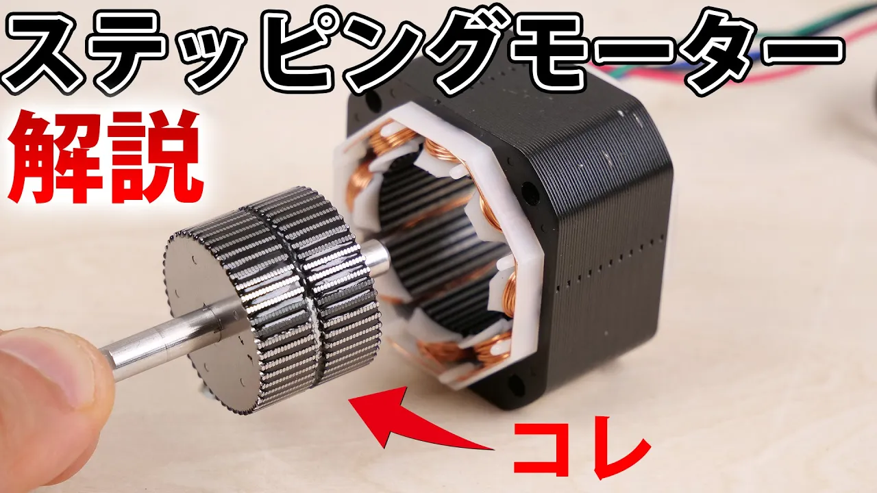
ステッピングモーターの動作原理, 構造について解説 【イチケン電子基礎シリーズ】
598.6K
This comprehensive section covers the complete working principles of stepper motors. It begins with the fundamental structure: rotors containing cylindrical permanent magnets with alternating N/S poles covered by toothed iron cores, creating apparent 100 poles from 50 physical teeth. The stator contains iron cores with coils. Two-phase motors have 8 coils (4 per phase) positioned at 45° angles. Rotation occurs through electromagnetic attraction between stator and rotor teeth, with phase sequence determining rotation direction. Three motor types are explained: PM (permanent magnet), VR (variable reluctance), and Hybrid (combining both for higher torque). Motor drivers control operation via pulse signals, with each pulse causing a fixed rotation angle. At low speeds, maximum torque is produced; as speed increases, inductive effects reduce torque. The section concludes with microstepping technology, which divides each full step into smaller sub-steps by proportionally controlling current in multiple phases simultaneously, increasing angular resolution and reducing vibration.
Click to watch →
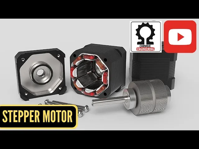
Stepper Motor, How it Works?
1.9K
Stepper motors are polyphase AC synchronous motors ideally driven by sinusoidal currents. There are four main excitation methods affecting running properties and torque. Wave drive energizes only one phase at a time, forcing the electrical system to rotate the motor with each 90-degree turn representing 1.8 degrees of actual rotation. Full step energizes both phases simultaneously, causing the rotor to align directly in the middle between poles, providing higher torque but larger step angles. Half step combines both methods by alternating between one phase and two phases, cutting the step angle in half (0.9 degrees) and reducing vibration. The rotor lines up at specific positions when one phase is energized, then in the middle when both phases are energized, enabling precise control through systematic phase energization sequences.
Click to watch →

moteur pas à pas المحرك خطوة-خطوة
49.3K
Stepper motors convert electrical pulses into rotational motion with steps matching control pulses. Three types exist: permanent magnet (rotor has permanent magnet), variable reluctance (non-magnetized iron rotor), and hybrid (combines both). Working principle involves producing magnetic fields through coils (phases), causing rotor alignment where magnetic flux is maximum. Unipolar coils have center taps with three terminals, always energized in same direction. Bipolar coils have two terminals, alternating polarity. Rotation direction depends on phase polarity. Three control modes: Full step (single-phase), Half step (asymmetric, doubles steps), Full step with maximum torque (two-phase). Step calculation: N = M × P × K1 × K2, where M=phases, P=rotor pole pairs, K1=1 for unipolar/2 for bipolar, K2=1 for full step/2 for half step. Step angle = 360°/N.
Click to watch →

#ApaITU? TB6600 Micro Stepper Driver
680
Stepper motors have 4 coils (A and B) that create magnetic fields. When coil A is activated, it creates a North pole at one end and South at the other. Reversing polarity reverses the magnetic field. The basic step sequence has 4 positions with 90-degree step angles. To achieve finer control, the step angle can be reduced to 45 degrees, creating 8 positions per revolution. This is achieved by activating only one coil at a time in different positions, allowing the motor to stop at intermediate positions.
Click to watch →
Microprocessor & Its Applications | Sensor Interfacing, Serial and Parallel communication | UNIT-3 |
724
A stepper motor is a brushless motor that operates in discrete steps, where each step corresponds to a specific rotation angle. The motor's step size depends on the number of teeth on its rotor—for example, a motor with 50 teeth and 4 poles requires 200 steps for one full rotation. The step angle is calculated by dividing 360 degrees by the total steps (360°/200 = 1.8°). Stepper motors use four phases (A1, A2, A3, A4) that activate sequentially: A1 turns on first, followed by A2, then A3, and finally A4. This sequential activation creates continuous rotation while maintaining precise position control.
Click to watch →
Deep Dive
Fundamentals of the Raspberry Pi Pico (RP2040) microarchitecture and programming basics in MicroPython or C/C++.

Raspberry Pi Pico RP2040 Programming in MicroPython, Complete Course for Beginners with Examples
78.9K
This tutorial introduces the Raspberry Pi Pico RP2040 microcontroller board, demonstrating how to program it using MicroPython with Thonny IDE through ten practical examples including LED control, pushbutton input, OLED display interfacing, analog sensor reading, ultrasonic distance measurement, temperature monitoring, day/night detection with LDR and relay, and motion detection with PIR sensor and buzzer.
Click to watch →

Intro to Raspberry Pi Pico and RP2040 - MicroPython Part 3: PIO | Digi-Key Electronics
32.2K
The RP2040 microcontroller features a dual-core ARM Cortex M0+ processor running up to 133 MHz, with no on-board flash memory requiring external storage. It includes built-in peripherals like UART, SPI, and I2C but lacks advanced features like I2S, SD card, and CAN bus. To compensate, the chip includes two PIO (Programmable Input Output) instances, each containing four state machines. PIO allows users to create tiny programs that emulate advanced peripherals, running independently of the main CPU without consuming processing time. Each state machine has its own program counter, two 32-bit working registers (X and Y), FIFOs for data transfer, and a clock divider enabling speeds from 2 kHz to 133 MHz. PIO uses a specialized assembly language with nine instructions designed for data movement in communication protocols. In MicroPython, PIO programs use the rp2 module with the @rp2.asm_pio decorator. Programs specify pins with direction and initial state, use wrap targets for infinite looping, and support delays up to 31 cycles per instruction. State machines are configured using state_machine() with parameters for state machine number, program name, frequency (minimum 2000 Hz), and base pin. The active() method starts the state machine, enabling concurrent execution where the main program can perform other tasks while PIO handles timing-critical operations.
Click to watch →

Raspberry Pi Pico PIO - 8 Little Processors You Can Program
104.5K
The Raspberry Pi Pico features the RP2040 processor with Programmable I/O (PIO), containing eight dedicated state machines for hardware-controlled GPIO manipulation. Each state machine includes FIFO queues, scratch registers, shift registers, and executes nine core instructions: jump, wait, shift, out/in, push/pull, move, set, and NOOP. This architecture enables deterministic high-speed I/O operations independent of the main CPU, suitable for protocols like UART, SPI, and I²C. Programming uses the StateMachine class with inline assembly syntax, where programs are defined as decorated functions and instantiated with specific pins and frequencies.
Click to watch →
![🍓 Programar Raspberry Pi Pico en 20 Minutos [Español] ⮞ MicroPython 🐍 N° 003](https://i.ytimg.com/vi_webp/-GvmHEzjF84/maxresdefault.webp)
🍓 Programar Raspberry Pi Pico en 20 Minutos [Español] ⮞ MicroPython 🐍 N° 003
42K
This tutorial covers the essential programming concepts for the Raspberry Pi Pico microcontroller using MicroPython, including basic Python syntax (print, comments), importing libraries (machine, utime), configuring input/output pins, implementing hardware timers and interrupts for precise timing, reading analog sensors via ADC conversion, controlling LED brightness with PWM, and utilizing multi-threading for parallel task execution on the dual-core RP2040 processor.
Click to watch →
Raspberry Pi Pico Análisis Instalación de MicroPython Proyectos con LED RGB Potenciómetro PWM
30.6K
The Raspberry Pi Pico is a compact microcontroller board featuring the RP2040 dual-core Cortex M0+ processor at 133 MHz with 264KB RAM and 2MB flash memory, supporting MicroPython programming. This tutorial demonstrates essential embedded programming concepts including GPIO pin configuration for LED control, RGB LED color manipulation, push button input handling with pull-up resistors, and PWM (Pulse Width Modulation) for controlling LED brightness through analog-to-digital conversion using a potentiometer. The board accepts 1.8-5V input and features 40 GPIO pins, making it suitable for various electronic projects.
Click to watch →
Deep Dive
The role and operation of motor driver ICs (e.g., ULN2003, L298N, or A4988) in interfacing logic-level signals with high-current inductive loads.

ULN2003 #shorts #electronic #electroniccomponent #electrical #technology #electronicdevice #motor
1.5K
The ULN2003 is a high-voltage, high-current Darlington transistor array integrated circuit that serves as a motor driver module, capable of driving inductive loads such as relays, solenoids, and motors with voltages up to 50V and currents up to 500mA per channel, featuring built-in flyback diodes for protection against inductive kickback.
Click to watch →

Palang pintu otomatis berbasis mikrokontroler ic 89s51
130
The L298N is a dual H-bridge motor driver IC used to control DC motors. It receives control signals from the microcontroller and provides sufficient current amplification to drive motors that require more power than the microcontroller can provide directly. The driver accepts logic-level inputs (high or low) and converts them into higher-current outputs capable of driving motors in both forward and reverse directions.
Click to watch →
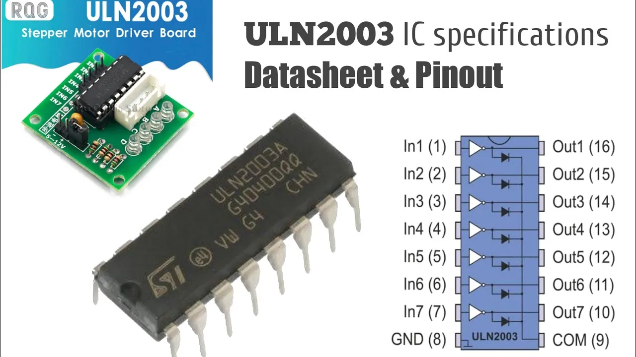
What Is ULN2003 IC? ULN2003A Datasheet & Specifications / ULN2003 Motor Driver
5.2K
The ULN2003 is an integrated circuit containing seven NPN Darlington transistors, each capable of delivering 500mA continuous current (600mA peak) at 50V output, with built-in flyback diodes for protecting inductive loads like relays and motors; it features TTL/CMOS/PMOS compatible inputs, outputs pinned opposite to inputs for simplified wiring, and can be paralleled for higher current applications, making it suitable for motor drivers, relay drivers, lamp drivers, and industrial equipment control.
Click to watch →

O incrível ULN2003 e suas aplicações!
74.8K
The ULN2003 is a 7-channel Darlington driver IC containing 7 Darlington pairs, each capable of 500mA. It simplifies circuits for activating multiple loads simultaneously. Key features include built-in flyback diodes for inductive load protection, TTL/CMOS compatible inputs, and operation up to 50V. Outputs can be paralleled for higher current (up to 2A). The 16-pin configuration includes 7 inputs (pins 1-7), 7 outputs (pins 10-16), common cathode (pin 19), and ground (pin 8). Each Darlington pair functions as an inverter, providing current amplification. Stepper motors require specific sequential signals to operate correctly, as they cannot be powered directly from a voltage source. The CD4017 CMOS counter generates sequencing signals, while a 555 timer provides the clock. PWM controls motor speed by varying the effective voltage applied to the coils.
Click to watch →

High-Side High Voltage IGBT-MOSFET Power Switches
9.7K
The ULN2003 is a Darlington transistor array integrated circuit containing seven high-current Darlington pairs. In motor control applications, it serves as a high-side switch driver that can handle significant current loads while providing built-in flyback protection. When used with an N-channel MOSFET, the ULN2003 can interface with microcontrollers by converting logic-level signals to sufficient gate drive voltages, enabling simple and reliable motor control implementations.
Click to watch →
Deep Dive
An introductory concept of Programmable Input/Output (PIO) state machines and how they offload timing-critical tasks from the main CPU.

Raspberry Pi Pico W LESSON 87: Introduction to Raspberry Pi Pico PIO and State Machines
5.9K
The Raspberry Pi Pico W features eight PIO state machines that act as mini-processors, each capable of running 32-line assembly programs at speeds up to 10 MHz; these state machines communicate with the main Python program through FIFO buffers (TX/RX) and four core registers (OSR, ISR, X, Y), enabling offloading of timing-critical tasks like GPIO pin manipulation, data shifting, and interrupt generation while maintaining efficient bidirectional data exchange via Python's put() and get() commands.
Click to watch →

LIVE RUMBLE IN THE JUNGLE: Raspberry Pi Pico PIO State Machines and Why They are SO Important
3.1K
The Raspberry Pi Pico's PIO (Programmable Input Output) state machines are dedicated hardware cores that provide precise timing control for tasks requiring exact timing, such as generating 10-microsecond pulses for ultrasonic sensors or controlling Neopixels, which cannot be achieved with Python on the main core due to interpretation overhead and background processes.
Click to watch →
The Factory | Device drivers with Raspberry Pi Pico PIO
6.2K
MicroPython lacks deterministic timing due to interpreter overhead and garbage collection, making it unsuitable for hardware protocols. The RP2040's PIO state machine solves this by executing PIO assembly code as Python functions with special decorators. Every PIO instruction executes in exactly one cycle, providing deterministic timing. PIO requires two pins: side set base (output control) and input base (data reading). The syntax includes input operations, output operations, and delay values, enabling precise hardware control for timing-critical applications.
Click to watch →

Raspberry Pi Pico Lecture 12 (2025): Introduction PIO
1.3K
The Raspberry Pi Pico's PIO (Programmable Input/Output) coprocessors are specialized hardware units that can execute custom assembly programs to control timing-critical peripherals like VGA displays, freeing the main CPU for other tasks; each PIO block contains up to four state machines with only 32 total instructions of shared memory, making them ideal for implementing custom digital interfaces such as SPI, UART, CAN, or VGA drivers with guaranteed single-cycle instruction execution.
Click to watch →
Raspberry Pi Pico PIO - 8 Little Processors You Can Program
104.5K
The Raspberry Pi Pico's RP2040 microcontroller features eight programmable state machines (PIO) that can be programmed in assembly language to control GPIO pins deterministically, enabling high-speed hardware-level I/O operations for tasks like blinking LEDs, data echoing, and bit manipulation without burdening the main CPU.
Click to watch →
Prerequisite Knowledge
- Concept 01Basic working principles of stepper motors, including phases, step angles, and coil excitation sequences.
- Concept 02Fundamentals of the Raspberry Pi Pico (RP2040) microarchitecture and programming basics in MicroPython or C/C++.
- Concept 03The role and operation of motor driver ICs (e.g., ULN2003, L298N, or A4988) in interfacing logic-level signals with high-current inductive loads.
- Concept 04An introductory concept of Programmable Input/Output (PIO) state machines and how they offload timing-critical tasks from the main CPU.
Subsequent Learning
- Step 01Implementing precise acceleration and deceleration algorithms (such as trapezoidal or S-curve profiles) to prevent stepper motor stalling.
- Step 02Developing multi-axis coordinated motion control systems for CNC machines or 3D printers using synchronized parallel PIO state machines.
- Step 03Designing closed-loop stepper motor systems by integrating rotary encoders to detect and correct missed steps.
- Step 04Utilizing PIO for other high-speed or deterministic hardware interfaces, such as custom display protocols, WS2812B LED strips, or high-speed sensor data acquisition.
Setup and purpose
Test execution
Speed adjustment
Setup and purpose
0:03Playing Section
- 1
Presenting stepper driver code and PIO hardware test on Raspberry Pi Pico.
- 2
Two Toshiba stepper drivers connected to linear rails for movement testing.
Dedicated Motor Driver ICs vs. Custom PIO Control
While using the Raspberry Pi Pico’s PIO (Programmable I/O) is an excellent educational exercise for learning digital logic and pulse generation, it is often impractical for real-world motion control compared to dedicated stepper driver ICs (like the TMC2209 or A4988). Stepper motors require precise analog current regulation, microstepping, stall detection, and thermal protection to operate quietly and efficiently without overheating. Implementing these features using PIO requires complex external discrete circuitry and significant development overhead. In contrast, dedicated driver chips handle these critical power-management and microstepping tasks entirely in hardware, requiring only simple Step/Direction signals from the microcontroller. For practical applications, relying on dedicated silicon is safer, more efficient, and vastly less complex than custom PIO implementations.
Deep Dive
Implementing precise acceleration and deceleration algorithms (such as trapezoidal or S-curve profiles) to prevent stepper motor stalling.
Controlling Stepper Motors with Arduino: A Guide
1.6M
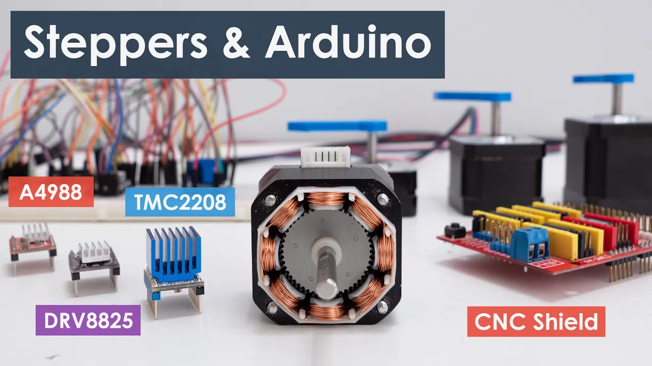
The AccelStepper library enables smooth acceleration and deceleration using setAcceleration() to define acceleration rate. moveTo() sets the target position, and runToPosition() moves the motor to that position while implementing acceleration and deceleration. This is a blocking function that pauses code execution until the motor reaches the target. For non-blocking operation, use run() within a while loop that continues until the motor reaches position. This allows the microcontroller to perform other tasks while the motor moves.
Click to watch →

Trinamic GUI stepper motor usage (position trapezoidal acceleration) with an TMC5160
271
The TMC5160 stepper motor controller uses a trapezoidal acceleration profile that controls motor movement through three phases: acceleration to maximum velocity, constant velocity, and deceleration to stop, with parameters like run current, standstill current, acceleration rate, and maximum velocity adjustable through the Trinamic GUI IDE to achieve precise position control.
Click to watch →
Aula 18 - Motion Delta: Configurando Rampas de Aceleração e Desaceleração
6.9K
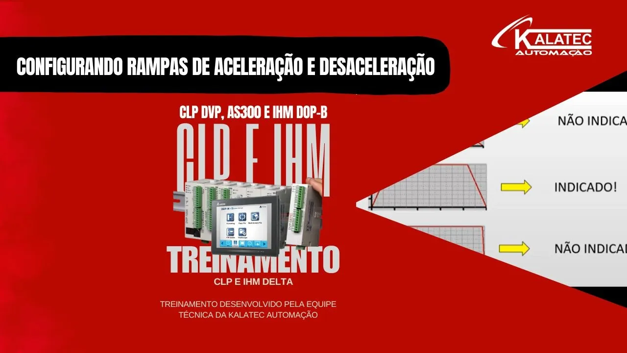
Proper configuration of acceleration and deceleration ramps is essential for stepper motor performance, with three ramp types available: triangular (no cruising speed, immediate acceleration and deceleration), trapezoidal (ideal for most applications, allows reaching cruising speed before decelerating), and square (not recommended for high speeds as it causes sudden starts/stops, vibrations, and reduced motor lifespan). The recommended practice is to reserve 20% of the total process time for acceleration and deceleration, with the remaining 80% for cruising at nominal speed. For example, in a 5-second process, 500ms should be allocated to each ramp phase. Configuration requires identifying the correct register addresses for each channel (e.g., 1343 for acceleration, 1381 for deceleration of channel 10) and setting values in milliseconds.
Click to watch →
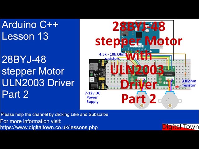
#104 Arduino C++ - Lesson 13 - 28BYJ-48 Stepper motor with ULN2003 driver. Part 2
418
To implement acceleration and deceleration in stepper motor control, track the current speed and adjust it incrementally based on user input. Each time the motor completes a step, compare the current speed to a target speed. If the target speed is higher (meaning slower movement since larger delay values result in slower stepping), increase the delay by a fixed amount. If the target speed is lower (faster movement), decrease the delay. This creates smooth acceleration or deceleration effects. The adjustment occurs per step, creating gradual changes in speed rather than instantaneous jumps.
Click to watch →
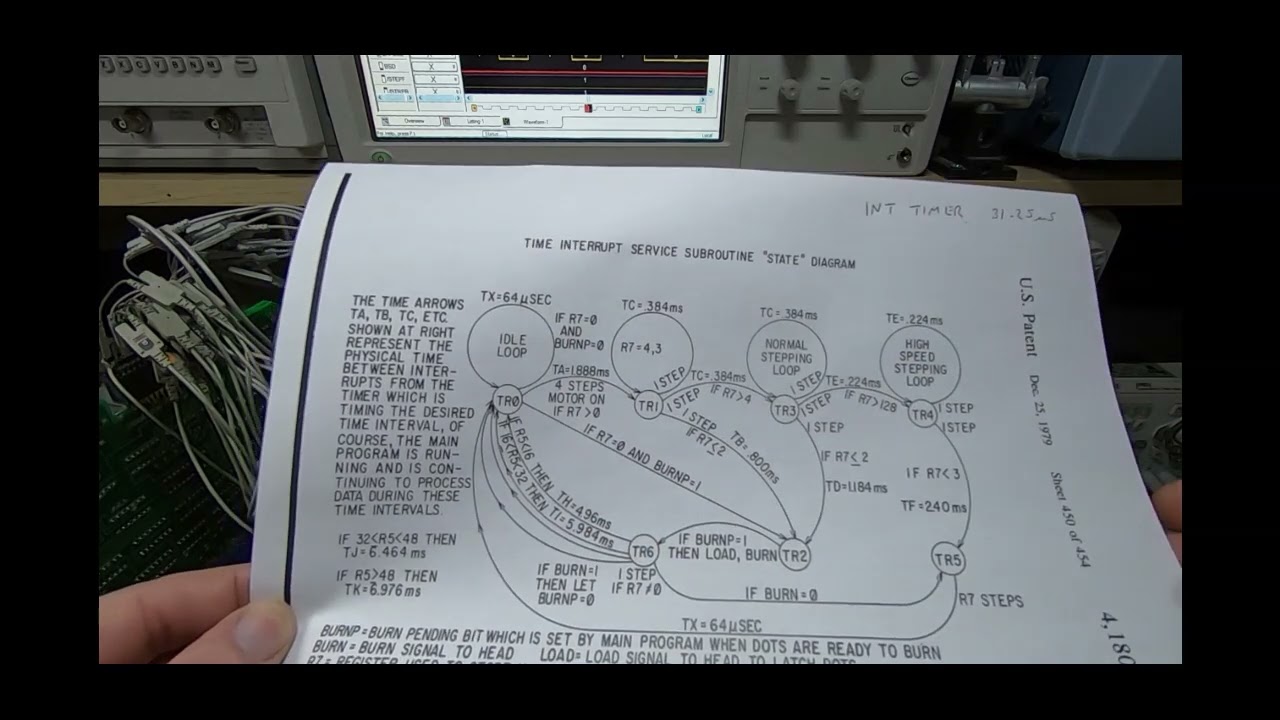
HP NANO Processor Part1
1.3K
Proper stepper motor control requires acceleration and deceleration profiles to prevent mechanical issues. Starting at full speed causes vibration and potential slippage, while stopping abruptly causes overshoot. The Nano printer code implements longer interrupt intervals initially to accelerate the motor gradually, shorter intervals at full speed, then longer intervals again toward the end to decelerate smoothly. This profile ensures precise positioning without mechanical stress, demonstrating how embedded systems implement sophisticated motion control algorithms within tight timing constraints.
Click to watch →
Deep Dive
Developing multi-axis coordinated motion control systems for CNC machines or 3D printers using synchronized parallel PIO state machines.

114 aula 23 CURSO PROGRAMAÇÃO CNC FANUC/ SIEMENS PARTE 6 ROTAÇÃO E AVANÇO. COMO DEFINIR E PROGRAMAR.
188
CNC machines can synchronize multiple axes to move simultaneously. When programming synchronized movement, the machine coordinates the motion of different axes (such as X, Y, and Z) to reach a target position together. This synchronization is important for operations where the tool must maintain a specific orientation or relationship between axes during movement.
Click to watch →
Raspberry Pi Pico PIO - Ep. 1 - Overview with Pull, Out, and Parallel Port
48.6K
Each PIO block contains four state machines, which are tiny processors that all run the same program. However, each state machine can access different input and output pins and can be sent different data. For example, if you needed four different UARTs, you could use the four state machines in one PIO block and assign different I/O pins to each. This allows multiple independent communication channels to run simultaneously.
Click to watch →

Raspberry Pi Pico W LESSON 100: Using Multiple PIO State Machines at the Same Time
2.8K
The Raspberry Pi Pico W has two PIO blocks, each containing four state machines that share a 32-line code limit. To control multiple servos independently, you can use different state machines on different PIO blocks (e.g., state machine 0 and 1 on PIO block 0, state machine 4 on PIO block 1), allowing you to utilize the full 64-line code capacity across all state machines. Each state machine has its own FIFO TX, FIFO RX, OSR, ISR, X register, and Y register, enabling independent operation while sharing the same code function.
Click to watch →

In-depth: Raspberry Pi Pico's PIO - programmable I/O!
163.2K
Each PIO state machine contains three main registers: a program counter pointing to the current instruction in memory, and two 32-bit scratch registers called X and Y. Additionally, there are two shift registers—the input shift register (ISR) and output shift register (OSR)—both connected to the FIFOs. The clock divider adjusts the state machine execution speed by dividing the system clock (up to 133 MHz) by values from 1 to 65536 with fractional precision of 1/256. The state machine connects to the IOQ system for synchronization and CPU alerting, and accesses GPIOs through the IO mapping system.
Click to watch →

Raspberry Pi Pico PIO - PIO Interrupts using C - Ep. 19
9.9K
Advanced PIO interrupt techniques extend beyond basic NVIC integration. For state machine interrupts 4-7 that lack NVIC routing, periodic polling of the IRQ register provides detection capability. Relative mode enables identification of which specific state machine triggered an interrupt when multiple machines share the same interrupt type by modifying the interrupt index based on state machine number. Multi-state machine synchronization can be achieved by having all machines wait on a common interrupt, allowing coordinated resumption when the shared interrupt is cleared. These techniques enable sophisticated parallel processing and timing coordination in PIO applications.
Click to watch →
Deep Dive
Designing closed-loop stepper motor systems by integrating rotary encoders to detect and correct missed steps.
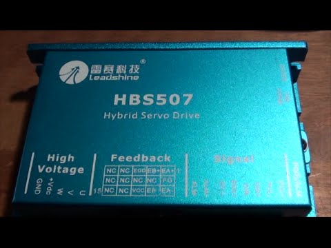
Setup of Leadshine HBS507 Closed Loop or Hybrid Servo Step Driver
79.2K
Closed-loop stepper motors (also called hybrid servo drives) solve the fundamental problem of ordinary stepper motors losing steps by incorporating an encoder at the motor output that continuously monitors actual position and sends feedback to the controller; this allows the system to detect and compensate for lost steps in real-time, ensuring precise positioning even under varying loads or obstacles, unlike open-loop systems where lost steps cannot be recovered.
Click to watch →
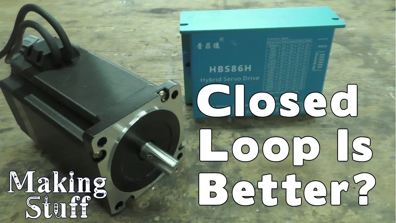
Closed Loop Stepper Motors for CNC machines
198.8K
Closed-loop stepper motors integrate encoders for bidirectional communication between motor and controller, unlike open-loop motors that lack feedback. The hybrid servo controller processes encoder signals to verify step completion, correcting missed steps and triggering alarms when limits are reached. This architecture provides automatic error detection, position correction, and enhanced safety features not available in standard open-loop systems used in 3D printing and hobby CNC applications.
Click to watch →

Closed loop stepper motors -- very impressive
177.2K
Closed loop stepper motors integrate optical encoders and drive electronics directly into the motor housing, eliminating the need for external drivers. Unlike conventional steppers that lose all position tracking when overloaded, closed loop motors can detect and correct synchronization errors. They automatically catch up when falling behind due to high speed or load disturbances, making them more forgiving in dynamic applications. This architecture enables direct connection to microcontrollers like Raspberry Pi without real-time constraints.
Click to watch →

#23 LinuxCNC & 5i25 - Closed-loop Stepper (PID , ENCODER , HALSCOPE)
23.2K
Closed loop stepper motor systems address the fundamental limitation of open loop steppers: step loss at high speeds due to reduced torque. These systems use encoders to continuously monitor actual motor position and compare it against commanded position. When discrepancies are detected, the controller compensates by adding corrective steps or adjusting drive parameters. This enables reliable operation at higher speeds and under heavier loads than open loop systems allow. The core principle applies regardless of whether the encoder is mounted on the motor or directly on the machine axis.
Click to watch →
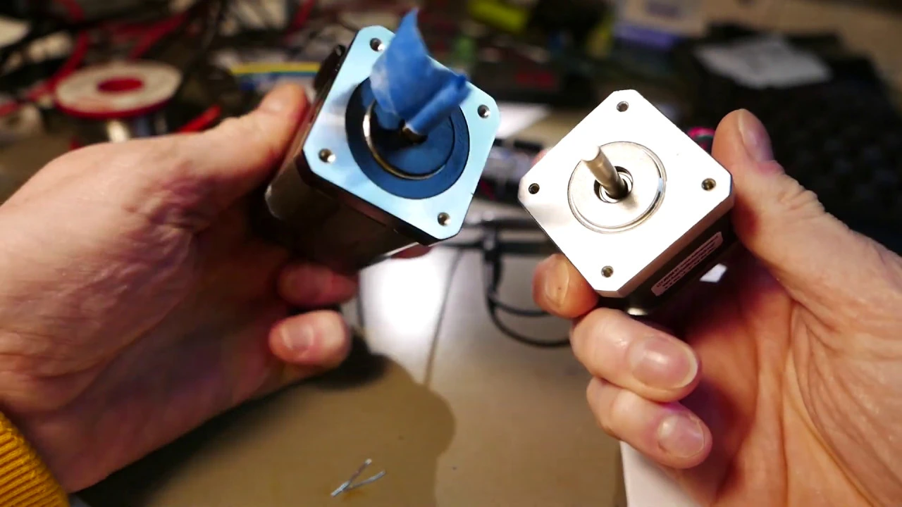
Leadshine Integrated Stepper test (Closed Loop Stepper)
2.1K
Integrated stepper motors combine traditional stepper motor characteristics with built-in optical encoders, providing closed-loop position feedback through in-position and alarm signals that detect step loss, enabling reliable operation at maximum speed without fear of losing steps.
Click to watch →
Deep Dive
Utilizing PIO for other high-speed or deterministic hardware interfaces, such as custom display protocols, WS2812B LED strips, or high-speed sensor data acquisition.

Raspberry Pi Pico - PIO explained
43.7K
The WS2812 LED chip requires precise timing for reliable operation: each bit uses PWM encoding with specific HIGH/LOW duration ratios, and the bus reset requires holding LOW for 50μs. Traditional software approaches struggle with these timing requirements due to interrupt overhead and CPU scheduling delays. The PIO solution addresses this by offloading the timing-critical I/O operations to dedicated hardware state machines, allowing precise 8ns-level timing independent of the main CPU. The main CPU handles only data preparation and DMA configuration, while the PIO manages the actual bit-level timing and data transmission.
Click to watch →
Raspberry Pi Pico PIO - 8 Little Processors You Can Program
104.5K
PIO enables diverse applications including blinking LEDs using delayed NOOP instructions, echo programs for bidirectional FIFO communication, and binary arithmetic via shift operations. The wrap_target mechanism creates infinite loops with optional initialization phases. Inline execution allows individual instruction testing. Common pitfalls include confusing set (direct pin control) with out (shift register output). These techniques form the foundation for implementing serial communication protocols, demonstrating how PIO transforms abstract data streams into precise physical outputs through deterministic hardware control.
Click to watch →
What is PIO | Programmable I/O on Raspberry Pi Pico
90K
Programmable I/O (PIO) is a unique hardware feature in the RP2040 microcontroller used in Raspberry Pi Pico that provides dedicated processing cores (state machines) to handle bit-banging operations for controlling non-standard hardware protocols, thereby freeing up the main processor to perform other tasks efficiently.
Click to watch →

What’s Behind the Light? – How WS2812B LED Strips Work
70.6K
WS2812B pixels contain three RGB LEDs controlled by onboard controllers. They require VCC (3.5-5.3V), GND, and DIN connections. Signal regeneration occurs at each pixel for cascading. Raspberry Pi's 3.3V conflicts with pixel requirements, necessitating level converters. Each pixel draws ~60mA at full brightness. The data protocol uses binary signals with 1.25μs intervals: logic 0 has 0.35μs high + 0.9μs low; logic 1 has 0.9μs high + 0.35μs low. Data must be sent continuously without delays >50μs, as pauses reset communication.
Click to watch →
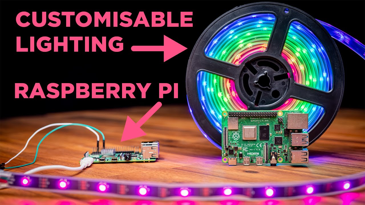
How To Use Addressable RGB WS2812B LED Strips With a Raspberry Pi Single Board Computer
210K
This tutorial demonstrates how to control fully addressable WS2812B RGB LED strips using a Raspberry Pi single-board computer, covering hardware connections (power, ground, and data wires), software setup (installing necessary Python libraries), and programming techniques (using Python scripts to control individual LED colors and animations), with guidance on power requirements for different strip lengths and multiple strip configurations.
Click to watch →
Setup and purpose
Test execution
Speed adjustment
Setup and purpose
0:03- 1
Presenting stepper driver code and PIO hardware test on Raspberry Pi Pico.
- 2
Two Toshiba stepper drivers connected to linear rails for movement testing.
Dedicated Motor Driver ICs vs. Custom PIO Control
While using the Raspberry Pi Pico’s PIO (Programmable I/O) is an excellent educational exercise for learning digital logic and pulse generation, it is often impractical for real-world motion control compared to dedicated stepper driver ICs (like the TMC2209 or A4988). Stepper motors require precise analog current regulation, microstepping, stall detection, and thermal protection to operate quietly and efficiently without overheating. Implementing these features using PIO requires complex external discrete circuitry and significant development overhead. In contrast, dedicated driver chips handle these critical power-management and microstepping tasks entirely in hardware, requiring only simple Step/Direction signals from the microcontroller. For practical applications, relying on dedicated silicon is safer, more efficient, and vastly less complex than custom PIO implementations.
Basic working principles of stepper motors, including phases, step angles, and coil excitation sequences.
Fundamentals of the Raspberry Pi Pico (RP2040) microarchitecture and programming basics in MicroPython or C/C++.
The role and operation of motor driver ICs (e.g., ULN2003, L298N, or A4988) in interfacing logic-level signals with high-current inductive loads.
An introductory concept of Programmable Input/Output (PIO) state machines and how they offload timing-critical tasks from the main CPU.
Implementing precise acceleration and deceleration algorithms (such as trapezoidal or S-curve profiles) to prevent stepper motor stalling.
Developing multi-axis coordinated motion control systems for CNC machines or 3D printers using synchronized parallel PIO state machines.
Designing closed-loop stepper motor systems by integrating rotary encoders to detect and correct missed steps.
Utilizing PIO for other high-speed or deterministic hardware interfaces, such as custom display protocols, WS2812B LED strips, or high-speed sensor data acquisition.
187 views2likes1:19@shabaz_Original Release: 2025-04-23
Hi, this is a quick test of some stepper driver code written by Jan Comps. He's written it to run on the PIO hardware uh on the um PI Pico board here. And this stepper board was actually created a while back, but I've never got around to testing it. Um, so there's a pie here and there's two Toshiba stepper motor drivers there and they're connected to these two linear rails. And after a few seconds, it should just run some test [Music] [Music] code.
[Music] Actually, the two motors were running at different speeds. Uh, but the the threads per inch is is different on the on the two linear rails. So, I sped one up just so that the the two platforms would move at the same speed.
Thanks for watching.
Up Next

20:00
S-Curve Motion Profile: Optimizing Jerk-Limited Motion Control
@codewithnima
647 views•2024-12-22

30:32
Ultrasonic Transducers: Resonant Frequency Measurement and Horn Design
@imajeenyus42
229.9K views•2017-02-22

54:16
Polymer Environmental Degradation: Mechanisms & Stabilization
@iit
1.8K views•2012-07-10

33:39
How a Student's Question Saved a NYC Skyscraper from Collapse
@veritasium
22.8M views•2025-04-26
Related Study Plans & Knowledge Roadmaps
Structured learning paths in Engineering
engineering
Building Acoustic Levitators: Physics & Arduino
01The Physics of Sound and Standing Waves
02Piezoelectric Transducers and H-Bridge Drivers
03Arduino Programming: Generating 40 kHz Signals
+ 2 more learning modules
14h5 modules
Explore Roadmap
engineering
Building Peltier Cloud Chambers: Particle Tracks
01Cosmic Rays & Cloud Chamber Physics
02Thermoelectric Cooling (TEC) Fundamentals
03Custom Liquid-Cooling Loop Design
+ 2 more learning modules
18h5 modules
Explore Roadmap
engineering
Yagi-Uda Antennas: Modeling, Build & VNA Test
01Introduction to RF and Antenna Fundamentals
02Yagi-Uda Antenna Design Principles
03Antenna Modeling and Simulation in 4NEC2
+ 2 more learning modules
18h5 modules
Explore Roadmap
engineering
ECG Monitor Design: Op-Amps, Filters & Noise
01Electronics & Breadboard Basics
02Op-Amps and Instrumentation Amplifiers
03Bioelectricity and ECG Fundamentals
+ 2 more learning modules
18h5 modules
Explore Roadmap