








![Serwomechanizmy | #74 [Podstawy]](https://i.ytimg.com/vi/MLhWv51sAk8/maxresdefault.jpg)










![New Building Game Lets You Build Transforming Robot Armies [Age of Warbots First Look]](https://i.ytimg.com/vi/8xaukGSIGp0/maxresdefault.jpg)













A 4-legged walking robot can be constructed using 3D printed parts (top plate, bottom plate, arm connectors, legs, and servo holders) with 8 hobby servo motors (4 for arms, 4 for legs), controlled by an ESP32 board with Bluetooth wireless communication and a simple mobile app for movement commands like walking, turning, and jumping.
DIY 4-Legged Walking Robot with ESP32: Build & Control Guide
Added:Basic Electronics and Power Management: Understanding microcontroller pins, PWM (Pulse Width Modulation) for servo control, and the necessity of external power supplies for high-draw motors.
C++ Programming and Arduino IDE: Familiarity with writing, uploading, and debugging code, utilizing libraries, and managing control loops.
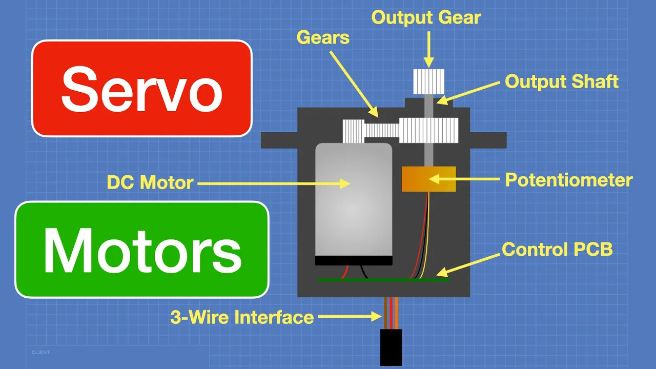
Hobby Servo Motor Fundamentals: Knowing how RC servos function, including angular rotation limits, torque requirements, and signal timing.
Basic Mechanical Assemblies: Comfort with interpreting physical assembly diagrams, utilizing fasteners, and understanding how rotational joints translate to walking linkages.
Inverse Kinematics (IK): Transitioning from hardcoded servo angles to mathematical coordinate systems to calculate precise joint angles for smooth foot placement.
Active Stabilization and IMU Integration: Implementing an Inertial Measurement Unit (like the MPU6050) to allow the robot to sense tilt and dynamically adjust its balance on uneven terrain.
Advanced Gait Planning: Exploring complex walking, trotting, and turning gaits to optimize speed, stability, and energy efficiency.
Wireless Control Protocols: Leveraging the ESP32's Wi-Fi and Bluetooth capabilities to implement WebSockets, ESP-NOW, or Bluetooth BLE for real-time remote control.
Autonomous Obstacle Avoidance: Integrating ultrasonic sensors, LiDAR, or an ESP32-CAM module to enable autonomous navigation and computer vision capabilities.
75.4K views1.4Klikes8:34Original Release: 2025-01-06
In this video I will show you how to make a simple four-legged walking robot using 3D printed Parts the design consists of only five main parts including the top and bottom plates arm connectors legs and Servo holders the four legs of the robot consist of four arm parts and four leg Parts a total of eight hobby Servo Motors are used for the robot movement four in the arms and four in the legs on the circuit side an esp32 board was preferred but the project can be easily controlled with Arduino boards the Bluetooth feature of the ESP board was preferred for wireless communication and a simple application was created for control the app allows you to control the robot's movements such as walking turning and jumping with simple commands this project is easy to assemble and use making it a great choice for students teachers or anyone interested in robotics let's get started first of all before assembling the servo Motors the arm servos to be placed on the base must be adjusted to the 90° starting position I have shared a basic code for the initial positions as you can see I have fixed three Servo Motors let's Mount the fourth and last servo motor together the holders on the servo base May remain slack according to the type of Servo motor in this case you can keep it fixed with the help of some hot glue in this section fix the arm and leg connectors which consist of two separate parts together with a bolt and nut attach the fixed connector to the base Servo then with the connector at a diagonal angle place the servo horn and fix it to the servo motor by tightening the screw finally fix the end of the servo horn to the connector using a screw it is not necessary to do this but fixing it prevents looseness now that the arm is complete let's move on to leg assembly before fixing the servo Motors to be used in the leg you need to bring them to a starting angle of 60° then place the holder and leg part fix the leg part to the servo motor with the appropriate screw insert the leg into the connector and attach the servo horn so that the leg is in the right angle position then fix the servo horn with the screws now prepare the other three legs and complete the assembly [Music] now that the Assembly of the arms and legs is complete we can move on to the power part of the circuit 7.4v battery will be enough for the circuit the base part was designed for the size of a 3s LiPo battery but the battery in my workshop was damag and I had to use an 11.1v battery if you were going to use a 7.4v battery you can skip this part I placed the battery under the base and fixed it with a cable tie due to the battery change I included a voltage step down module in the power circuit I set the voltage output to 7 volts with the help of the adjust screw on the module and connected the battery inputs after placing the module on the base let's continue by assembling the upper base where the circuit board will be fixed all the parts of the robot are assembled let's move on to the circuit board I designed a circuit board that controls 16 Servo Motors and can be attached to an es 32 board as always I chose PCB way for high quality circuit board prints also PCB way offering great gifts and incredible discounts for the new year last seven days for New Year deals visit the link in the description to check both this project details and New Year discounts you can also find the list of required components in the video descriptions easy solderable components are preferred basic soldering knowledge will be enough now it's time for soldering [Music] now that the board is ready let's place it on the robot and then make the servo motor connections the source code section shows which pins the servo Motors are connected to the robot is almost ready remove the ESB board and connect it to your computer then open the shared source code first let's install esp32 from the file go to preferences and add the shared esp32 board manager URL this step ensures that we can install the necessary esp32 tools now go to board manager search for esp32 and click install this adds the esp32 board support to the Arduino editor now we can take a closer look at the code the code contains two libraries Bluetooth serial is used to handle Bluetooth communication esp32 Servo is a library specifically designed to control Servo motors with esp32 boards the application sends designated numbers via Bluetooth to activate generated commands such as up down walk and others these numbers are defined in the app and the commands are interpreted in the code to triggered different robot movements in this section we specify the gpio pins to which the servo Motors are connected each arm and leg of the robot is controlled by separate Servo Motors the robot's movements are defined with specific limits for the arms and legs the speed of these movements is controlled by the speed variable in the loop section the code checks if any data is received from the Bluetooth app if data is available it is read and stored in the data variable based on this data specific robot functions are triggered when a command is received the robot performs actions like walk rotate or reset to a stable position that's the working principle and requirements of the code now upload the code to the board and then let's move to the application side we will be using MIT App Inventor a free and drag and drop tool for developing Android apps after logging into App Inventor by email upload the shared AIA file of the app I cre created this way you can examine the blocks and build your own Android installation file without any trust issues then all you need to do is install the app on your phone or tablet now let's talk a little bit about the interface of the app there is a button to list Bluetooth devices just below it I added a text label showing the connection status finally I added six buttons to trigger the robot's motion functions in the block section there are a few conditions that initiate Bluetooth communication at the very beginning then the data type and data functions to be sent for each movement button were created it's that simple now we have an application now it's time to control the robot you can find all the details of the project from the link in the video description thank you for watching [Music]
Up Next
43:06
Arduino Servo Motor Control: PWM, PCA9685, and I2C Tutorial
@Dronebotworkshop
1.5M views•2018-05-20

12:54
Triumph of Orthodoxy Icon: Byzantine Art & History Explained
@BenCallan
2.1K views•2024-08-06

9:49
FastAPI vs Flask vs Django: Choosing the Right Python Web Framework
@TechWithTim
302.5K views•2024-05-26

1:42
Game of Thrones Opening Credits: A Cinematic Analysis
@gameofthrones
46.3M views•2011-04-18
Related Study Plans & Knowledge Roadmaps
Structured learning paths in General & Interdisciplinary Studies
general-studies
Elevator Engineering: History, Physics & Cities
01From Hoists to Safety Brakes: The Dawn of Vertical Lift
02Hydraulic vs. Traction: The Engineering Physics of Elevators
03Modern Speed, Safety, and Algorithms
+ 2 more learning modules
12h5 modules
Explore Roadmap
general-studies
Rubber: Material Science, History & Geopolitics
01Origins of Natural Rubber & Mesoamerican History
02The Chemistry of Natural Rubber & Vulcanization
03The Geopolitics of the Rubber Boom & Colonization
+ 2 more learning modules
12h5 modules
Explore Roadmap
general-studies
Containerization: Evolution, Logistics & Trade
01Ancient Trade & Bulk Cargo: Amphorae to Barrels
02The Industrial Revolution & Cardboard Packaging
03The Containerization Revolution: Malcom McLean
+ 2 more learning modules
12h5 modules
Explore Roadmap
general-studies
Textile Tech: Evolution, Labor & Global Impact
01Pre-Industrial Textiles: Handloom & Cottage Industry
02Mechanization: The Spinning Jenny to the Power Loom
03The Factory System & Global Labor Transformation
+ 2 more learning modules
10h5 modules
Explore Roadmap