























](https://i.ytimg.com/vi/A4pb1xv8olk/maxresdefault.jpg)

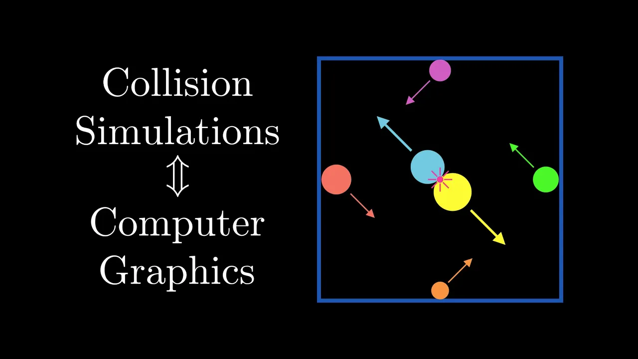
The Separated Axis Theorem (SAT) is a fundamental algorithm for detecting collisions between convex polygons by projecting all points of each polygon onto axes perpendicular to each edge of both polygons; if the projections overlap on all axes, the polygons are colliding, otherwise they are separated. An alternative approach involves testing intersections between diagonals of one polygon and edges of another polygon, which can also detect collisions and provide additional information for static collision resolution.
Convex Polygon Collisions: AABB and Separating Axis Theorem Explained
Added:Vector Mathematics: A solid understanding of 2D vectors, dot products, vector projection, and finding normal vectors.
Geometric Properties of Polygons: Knowing the difference between convex and concave polygons and why certain mathematical theorems only apply to the former.
Foundational Collision Concepts: Familiarity with basic bounding volumes (like circles and AABBs) and the distinction between broad-phase and narrow-phase collision detection.
Coordinate Systems: Understanding how 2D screen/world coordinates function in programming environments and game engines.
Dynamic Collision Resolution: Implementing impulse-based physics to calculate realistic post-collision velocities, forces, and angular momentum.
Continuous Collision Detection (CCD): Addressing the 'tunneling' artifact where fast-moving objects pass through boundaries by utilizing sweep tests or time-of-impact (TOI) algorithms.
Spatial Partitioning Techniques: Learning broad-phase optimization structures like Quadtrees, Octrees, or Spatial Hashing to handle collisions efficiently among hundreds of objects.
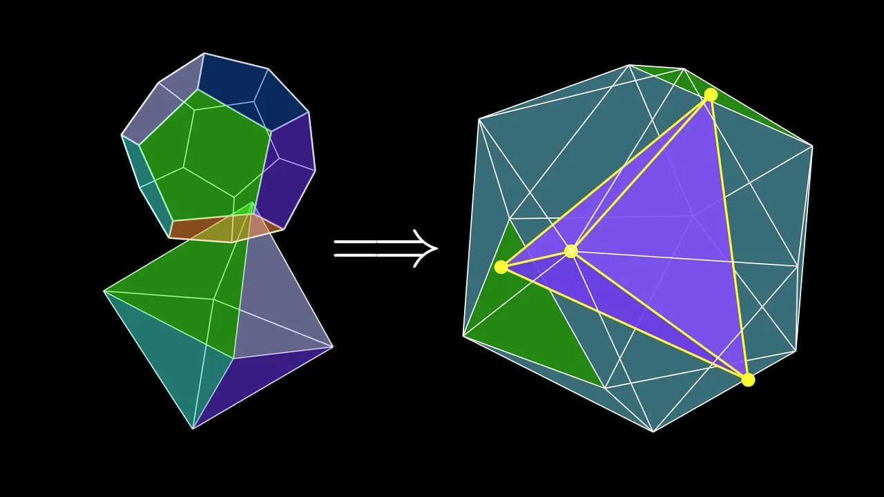
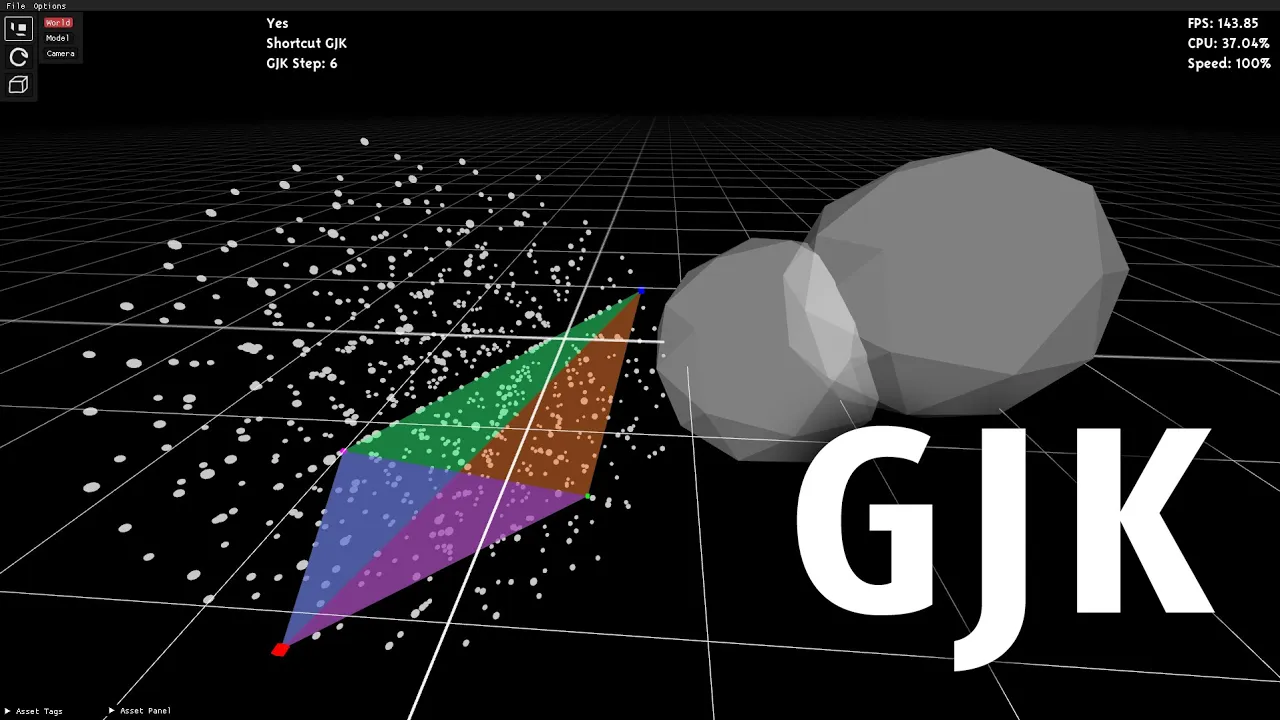
GJK (Gilbert-Johnson-Keerthi) Algorithm: Exploring advanced, faster mathematical frameworks for narrow-phase distance and collision detection of convex shapes in both 2D and 3D.
Concave Polygon Decomposition: Implementing triangulation or convex decomposition algorithms to handle complex, non-convex shapes using the Separating Axis Theorem.
136.4K views4.1Klikes36:40Original Release: 2019-02-02
hello in this video I'm going to be introducing several techniques to handle collisions between convex polygons and I'll even look at handling collisions in a static fashion too but I've got two things to mention just before we get started firstly anything you can do to a convex polygon you can also do to a quadrilateral so those of you with tile based systems using rectangles and squares all of this material should be very relevant to secondly it may seem like a horribly complicated thing convex polygon collision detection but it isn't I want to focus on the algorithms rather than the code for this video and so the coding sections may go a bit quicker than usual however I encourage you to download the source file from the github and study it for yourselves let's get some of the very basics out of the way first as my regular viewers will know by now I draw everything by hand so technically nothing you'll see on the screen is a polygon a polygon is defined by points connected by straight edges and as you can see I'm no good at drawing straight things on my screen and what I have here is called a concave polygon and concave polygons present all sorts of problems I'm not going to discuss in the video simply because they have something like this and a concave polygon can be identified because it has at least one internal angle that is greater than 180 degrees and so for this video we're not interested in concave polygons are interested in convex polygons which means all of the internal angles are less than 180 degrees now I know that a large part of my audience builds simple 2d games and so we mustn't forget that rectangles and squares are also convex polygons and the algorithms I'm going to show today there are some explicit optimizations you can make if your system only contains quadrilaterals such as this but the code I'm going to show is for arbitrary sided convex polygons however I just want to get out of the way one little thing which deals with just rectangles only and you may have heard of it it's called AABB which stands for axis aligned bounding box and this is an incredibly simple collision detection routine just four squares and rectangles and specifically four squares and rectangles that haven't been rotated and this means given an axis of a world in our x and y directions the sides of the quadrilateral are parallel to those axes checking to see if two axis aligned quadrilaterals overlap is very trivial if I label this one P and this one Q we can intuitively see that in the x axis if this side of P is less than this side of Q and this is just for x axis then there is potential for overlap because if this highlighted side of P was greater than the right-hand side of Q clearly they wouldn't be overlapping we can confirm this with another check that if this side of P is greater than this side of Q then in the x axis these two quadrilaterals are overlapping and so if I label this as X and this point is X plus width of that rectangle and the same applies for Q we know that there's overlap in the x axis if P X is less than Q X plus W and P X plus W is greater than Q X and because our quadrilaterals axis aligned whatever applies in the x axis also applies in the y axis so we can simply duplicate the formula replacing X's and w's for wise and H's H being height of course I'm not even going to code this up because it's so simple and quite obvious but I felt it needed a place somewhere in this presentation as usual before we get stuck into the algorithms I'd like to just demonstrate the kind of thing I'm going to be building today and this is just a little program that demonstrates to alternative methods for detecting overlap between convex polygons and Quincy we've got a selection of convex polygons on the screen I've got a Pentagon which I can move around the line from the middle of the Pentagon to the outside just helps with the direction so I know how to steer it and with the arrow keys I can move the Pentagon around with the WASD Keys I can move the triangle around I can't move the square around in the bottom corner and with the function keys I can choose between four different options of the algorithms the first is called separated axis theorem and as you'll see as I move the Pentagon into the square it's changed red that indicates that overlap has occurred in fact I can go over the triangle and the same thing happens and it's very very precise for now the alternative algorithm at where I look at diagonals versus edges gives exactly the same result I can move the triangle into the quadrilateral as well detecting whether two polygons overlap is very useful but if we wanted to actually constrain them from overlapping we need to apply some sort of static collision resolution and so I can press f2 to select static for the separated axis theorem version and we'll see what happens so I can control the Pentagon we can see it doesn't go between the shapes but each other's a little bit I can't force it into the other shapes now the shapes have a degree of priority so if I push the triangle I can push the other shape around but I can't push the quadrilateral around with the triangle we can see the collision is quite robust there's no dynamic response is implemented here so the feel of what's going on may look a little strange because you'd expect it to rotate and bounce accordingly this is just static resolution it's just a way of stopping the shapes from overlapping the alternative method using the shapes diagonals and we will go into some detail about these methods during this video I feel is a little bit more numerically stable so if I take the Pentagon this time and what we notice is well I set it up there's actually less juddering as part of the resolution the diagonal method approach is a little bit more computationally into but fractionally so but I think the results and the stability are just a little better so let's get started with the rather traditional separated axis theorem here I have a polygon and here I have another firstly we can see they're both convex and secondly we can see they're not axis aligned in any way this approach involves looking at the shadows of the shape along an axis and checking if for that axis the shadows overlap in fact we're going to check against several different axes and if the shadows overlap for all of those axes we know that the two shapes have collided one overlaps the other so what are these mythical axes well I'm going to create an axis relative to each edge of each polygon and I'm going to do that by simply taking the normal of an edge so taking this edge of this triangle I'm going to create an axis relative to that normal now it doesn't matter where that axis actually exists in space as long as we have something this is parallel to it so I'm going to translate that axis down here it just makes the drawing a bit clearer and now I'm interested in the normal to that axis which is of course the original direction of the edge of the polygon to begin with and somewhere in space up here I'm going to turn a light on and this is a special light because it transmits light globally but in a single direction this means that all of our points will cast a shadow onto this axis and we look at all points on both shapes for each shape we then work out the minimum and maximum extent of that shadow so for the quadrilateral here we can see the two big red points on the axis and for our triangle we've got the two big blue points we've got the two shadows of the two shapes and what do we see well the shadows overlap and using a method very similar to the axis aligned bounding box I've just described we can consider that for this particular access we've got overlap and so far our shapes must be overlapping this algorithm requires that we repeat this process for every edge of both shapes in fact it'll be for every edge of all shapes we want to test collisions between so let's consider two shapes that are not overlapping and we'll start with this edge so we'll take the normal of this edge to create our axis and this is called the projected axis I'm not going to translate it this time I don't need to use the light bulb analogy anymore I think you can see how we can crush these points onto this axis when we project the point onto this axis we can see in this instance there is no overlap between the two shapes and if we find one axis that has no overlap then the shapes can't be in collision they are indeed separated along that axis things get a little strange when we try to assign numeric values to what's going on here but ultimately the numeric values of things is quite irrelevant because it's all relative to one particular system so how do we actually do these projections well quite simply it's just the dot product between two vectors one of which is our axis of projection and the other is a vector to the point now these two points naturally at 90 degrees to our normal and when you do the dot product between two vectors you get a scalar value in this case the scalar value is 0 because don't forget our dot product in this case is going to be px times n ex plus py times NY and we've done dot product as projections quite a number of times on this channel and in the past I've referred to this method of dot products as being an indication of how similar two vectors are if I just quickly describe two vectors here this one is going to 1 0 and this one is going to 0 1 and we apply the above formula we've got 0 times 1 plus 1 times 0 which is 0 the vectors are not similar at all and this is quite right because they're at 90 degrees to each other if on the other hand we had a point going to one we end up with one times one plus one times zero clearly a 1 and we can see here if we were to drop a shadow down from that particular point of course the result is 1 this also applies to vectors going in the opposite directions except this time you have minus signs and so for this simple polygon the one outlier is of course this point and if we take the dot product between this point and the normal we end up with the projection along the normal axis our axis of projection and this gives us some value let's call it Q naturally these two other points also were projected in exactly the same way and they gave us 0 in this case but that doesn't mean we should ignore them it just means we've got another pair of values in this case both equal to 0 which I'll call Q Prime we can then test Q and Q prime to work out what's the length of the shadow along the projected vector is and if the shadow for a particular axis of all points tested between both shapes being tested if they overlap then for that axis they're in collision if for any of the axes we test there is no overlap then the shapes are not in collision and we can abort the algorithm and that's really it we're taking all of the points crushing them from two dimensions to one dimension and then comparing the extent of those points per shape to see if they overlap so let's take a look at implementing separated axis theorem in code but before we can start testing whether polygons overlap we need some system of actually representing a polygon manipulating it and drawing it to the screen and of course I'm going to use the pixel game engine for this and as I mentioned at the start of the video I'm already going to use some code I've created but I will just talk you through what's going on here so in the main function I'm creating a pixel game engine of resolution 256 by 240 and each pixel size is going to be 4 by 4 screen pixels in the game engine class I've created a simple struct that represents a point in two dimensions and I've created a simple polygon structure which contains a vector of points because a polygon can have any number of points but I've also included a central position point for that polygon and an angle and I'll use these two variables to transform the shape from the local space of the shape to the world space and that's what these vectors are so here is another vector of 2d points and this is the original model of the shape this vector P will be updated every frame with the translated version of the model of the shape and we did exactly this many times for the console game engine in videos such as code at yourself asteroids and the code at yourself worms series where we had wireframe models so we take an original model use these values to translate that model into world space and the model in world space is represented by this vector of 2d points finally we've got a flag which represents whether it overlaps and I'm using that to color the shapes I only use three shapes for this demonstration but I could have many so I'm going to store those in a vector of polygons called vac shapes in on user create I'm going to define my three shapes the first is a Pentagon so that's got five sides and so I loop through all five points and using cosine and sine I can work out where those points are relative to the origin of the object 0 0 I can do exactly the same for a triangle but this has only got three points of course so the angle I'm passing in is 2 pi divided by 3 finally my third shape is a quadrilateral and just to be a bit different I'm hand crafting the coordinates again it's relative to the origin so this is minus 32 plus 30 around the center point 0 0 and when we translate from model space into world space that origin will be translated to 50 200 and we'll rotate the model as necessary depending on the angle value you'll also notice that I'm pushing these coordinates to the OV actor which represents the original model but I'm also pushing them to the P vector that's just to initialize the P vector to the same number of points and to make sure that the points are the same finally I add the three shapes to my vector of shapes in on user update I've got a little bit of user input code so this is just to handle the keys now I'm using the arrow keys to control shape one and I'm using the W a s and D keys to all shaped - if the user presses left or right or a or D I just want to increment or decrement the angle for that shape and I modulate my F elapsed time to account for variability in the frame rate if they press the up or down keys I create a unit vector based upon the angle using cosine and sine and displace the shapes position by an amount along that unit vector I scale it to 60 here which is the equivalent of setting the speed of movement of course if they press up it goes one way and if they pressed down it goes in the opposite direction I do exactly the same for shape two once I've got the user input sorted out and I've updated the shapes position I then need to transform the shapes model into world space and that's done through this little Auto for loop so I iterate through all of the shapes and then for each point in the shapes model I calculate it transformed position and this is just a combined 2d matrix transform so we can see here with the cosines and the sines I'm handling the rotation based on the angle and I'm offsetting the final position by the center coordinate I'm also going to take this opportunity since I'm going through all of the shapes to set the overlap flags to false finally I want to draw the shapes so again I iterate through all of the shapes using little Auto for loop and I draw a line between successive pairs of points and I can access these points through the index I that's why I'm not using an auto loop here because I know that successive points are I and I plus 1 I just need to be careful though because I want my shape to be closed and I don't want to access points that don't exist so when I'm taking on the neighboring point I use the modulus function with the size of the number of points in the point vector this will ensure it wraps background and closes the shape for me finally depending on the overlap flag I choose the color of the shape if it is overlapping I'm going to color it red if not white it's quite convenient to know what direction the shapes are facing in so you can control them sensibly so I draw a single line from the middle of the shape to the first point and that's really it for the startup code I update the shapes position based on user input and I draw them to the screen at the moment I'm not checking for any overlap but let's take a look to make sure that this works so there are my three shapes the arrow keys control shape one which was the Pentagon and the W a s and D keys control shape two which was the triangle I'm going to create a function called shape overlap separated axis theorem and this will return true if the shapes indeed overlap we're going to pass it to polygon arguments and this function will return are they overlapping the algorithm has a lot of repetitive code and I have to test each edge of both shapes but I don't want to have lots of repetitive code in this function I also don't want to do any vector trickery such as merging the two sets of points together so I'm going to create two pointers at poly one and poly two and set those to the address of our shapes and well first of all test one shape against the other then we'll swap these pointers around to test the other shape against the original one it'll become a bit clearer when we start writing some code I know that for this function I'm only going to be testing at two shapes to see if they interact so I'll create a small for loop just to select each shape if the shape is zero I'm happy with poly one equaling r1 but if the shape is one I want to swap them around so a quick little check for that now it doesn't matter which shape poly one represents we know we want to go through each edge of that shape and create a projective axis and in much the same way I drew the shapes I'm going to use the index of the point in that vector and the index plus one of course making sure I wrap around using these two indices I can extract the points at the ends of an edge segment on our polygon so here I've got it for the y-axis and here I've got it for the x-axis subtracting these two points will of course give me a vector along that edge however I want a normal to that edge and so that's why when I'm constructing my axis projection vector I'm passing the Y's into the X location and inverting it and passing the X's into the Y location this will give me a normal to the edge firstly I want to project all of the points of the first polygon onto that axis of projection but I also want to work out where the minimum and maximum extents of the projection lie so I'll create two variables min R 1 and Max R 1 and I've said them to infinity and minus infinity and you'll see why in a minute so with the one axis of projection I'm now going to iterate through all of the points on the first polygon and I simply calculate the dot product between that point and the axis of projection this gives me a scalar value don't forget now instead of storing all of the scalar values for all of the points of the polygon I am only interested in the minimum and the maximum so as I go I'm going to calculate the minimum and the maximum once I have the extents of the projection for shape 1 I do exactly the same but with shape 2 and finally and this is why I wanted to introduce AABB in a very similar way I check to see if those extents overlap if they do overlap I just want the loop to continue if they don't overlap then the shapes are not colliding I can abort now and just return false if however I get overlap for all axes I get to this point and I can return true the shapes must be overlapping if this is the case just a quick little summary of what we're doing we're going to test two shapes against each other for collision but we need to test one against the other and then flip them around and test one against the other this ensures that we create an axis of projection for all edges of both shapes once we've got that axis of projection we take the points for shape one and work out where the shadow lies along that axis then we take the points for shape two and also work out where the shadow lies along that axis and then we check to see do the shadows overlap if there is any axis where the shadows don't overlap we return false because the shapes are not in collision however if on all axes the shape shadows do overlap then they are in collision so we return true all that's left to do now is to call this function so for the particular shape that I'm testing I'm going to call our shape overlap separated axis theorem function and pass in the two shapes one little point about this loop's they set up in such a way that shapes cannot be tested against themselves it's also set up in a way that we only test a pair of shapes once so let's take a look I'm going to drive my Pentagon into the quadrilateral we see the shape turned red and we can get it let's have a look how accurate it is the edges are probably not touching there but let's just back it off a little bit there we go it is quite accurate so that's very nice let's go and test with our triangle and oh dear we see it's not overlapping with the triangle why is this well simply put it's because of the order of tests that were performing we're basically testing is the Pentagon interacting with the triangle and then is it interacting with the quadrilateral and so even though it clearly was overlapping the triangle when it was tested against the quadrilateral it returned false so that resets the overlap flag of our Pentagon so I'm going to just accumulate with the logic all here so if any of the shapes caused an overlap with the Pentagon then it remains set so let's try it now so we can try our triangle there we go it gets set to red and we can try a quadrilateral and that gets set to red let's also move our triangle around there we go very nice depending on your application you may want to structure the order of collisions in a slightly different manner it really is application dependent and so that is separated axis theorem now it's a bit of a bonus too for one video this when I first started thinking about collisions between convex polygons of course I knew separated axis theorem existed and was readily used by a lot of people but as a program I feel it's important to try and think about things from first principle sometimes you know just to keep the brain ticking over and so I wanted to develop an algorithm which would give the same effect a separated axis theorem but approach it from a different perspective now full disclosure this algorithm that I'm about to show could well exist it could be used by lots of people I don't know I've not researched it I don't have a name for it if it does have a formal name please leave a comment below but for now I'm doing it diagonals one of the properties of a convex polygon is nothing can fit inside it ie the boundary of the polygon is equal to its convex hull in contrast a concave polygon isn't the convex hull would require this edge to therefore if I draw a line from the midpoint of the polygon to one of its external points and dubbing these that diagonals I can be sure that the diagonals never leave the boundary of the polygon this is not the same of course for a concave polygon if I take some midpoint that one's fine ooh this one the diagonal has left the boundary of the shape not good and this one and this one then this one by knowing that all of the diagonals lie within the boundary of the shape anything that intersects those diagonals must mean that something has entered the shape knowing this we can test the diagonals of one shape against the edge segments of another this means we can use a very common line segment intersection algorithm to test the two lines the output of a line segment intersection algorithm is usually a parametric value that represents the distance along that line typically normalized to the location where that intersection occurs and this is usually denoted by t2 I'll have t1 for that line and t2 for that line in this instance T would begin at 0 here and end at 1 here and begin at 0 here and end at 1 here and this gives us some incredibly useful information we know that at this intersection point along this diagonal we've intersected with another shape so we'll call that distance t1 but because we know that the length of this diagonal is always going to be 1 we know how far the diagonal has penetrated the shape it's simply 1 minus t1 this means we can displace the shape backwards by 1 minus t1 multiplied by the length of that diagonal very simply we can statically resolve that collision now in much the same way as separated axis theorem once we've tested one shape we have to flip them around and test the other shape because we can see in this situation none of the original triangles diagonals intersect with any of the edges of the second shape but this time one of the second shaped diagonals intersects with an edge of the triangle and depending on how we want the response to work we can either displace the quadrilateral backwards by this distance or we can push the triangle forwards by that distance this will depend on the application so with this diagonals edge intersect approach not only do we get overlap information we also as a by-product get information on how to statically resolve it and I feel it's also a little bit more intuitive than doing vector projections though admittedly not as mathematically clever so let's code this up I'm actually just going to copy the method we've already created because the outline code is pretty much the same I want to check one shape and then the other except this time I'm going to call the function diag I'm going to remove the separated axis theorem component so in principle we're going to have two nested for-loops the first is going to check the diagonals of polygon one against the edges of polygon two now specifically I'm interested in line segments not lines so a line segment is defined by start and an end point and for clarity I'm going to add these in and label them slightly differently so for our diagonal I'm going to take the midpoint of the shape as being the starting point of our line segment and a point on the boundary of the shape as the end point of the line segment in much the same way I'm going to create a line segment that represents the edge of the second shape this time I'm taking a point from the edge and I'm taking its neighboring point remembering to wrap around to close the polygon I've covered line segment intersections in several other videos and you can google it and get it straight away but this is the equation for it and this will give me t1 and t2 values I know that if both my t1 and t2 values lie between 0 and 1 then the line segments are crossing each other if one of these values is outside of 0 and 1 then the lines are crossing each other certainly but not within the boundaries of the line segment start and end points so if the line segments cross I'm going to return true I don't need to do any further tests I know I've got a collision if nothing returns true then I can return false I know that no segments have crossed each other and so that's it it's very simple we take the diagonal of one shape test true intersection against the edge of another and if it returns true we're going to set the overlap flag of our first shape to true so we're testing for overlaps I'm going to copy that line paste it in comment out the first one and change this to diag let's take a look to cut our shapes Pentagon we'll go down to the quadrilateral straight away it behaves in a very similar way to the separated axis theorem and it's a little bit beyond my mathematical abilities but I'm fairly certain you could prove that this is a very accurate method but let's not forget that because we have generated t1 and t2 values we've also got the information to resolve this collision statically instead of modifying this function I'm going to copy it and create a new one and I'm going to call it diag static so this function will test for collision and try to resolve it it doesn't matter which polygon we are testing we will want to create a vector that represents the displacement to set the original polygons of position two to get it out of a collision now the polygons could be overlapping in such a way that there are multiple diagonal and line intersections occurring if I want to displace the polygon accurately I don't want to just abandon it at the first attempt it might detect an intersection and say the shapes are overlapping but it won't displace it accurately to stop that overlap from occur so I'm going to accumulate displacement depending on how many intersections occur so here we can see the 1 minus t1 value and I'm going to displace along the diagonal which we can represent as a vector by subtracting the two points at the end of the diagonals line segment if we make an assumption that shape one is the one we always want to respond to static collisions then during the first rounds of tests the shape pulls itself out of the body it's collided with but during the second round of tests the body pushes the shape out so this displacement vector we need to change the polarity of depending on the order of the pear shapes we're testing and so I'm doing that here using the shape index from our original for loop to determine whether we multiply by minus 1 or plus 1 and I directly change the original shapes location because we have statically resolved the collision there is no chance of overlap occurring so this function now will always return false again let's test the theory creates a copy comment that line out and this time we're going to statically resolve the collision let's take a look I've got my Pentagon I'm going to try and crash it into the quadrilateral and I can't the diagonal of the Pentagon is pushing into the edge segment of the quadrilateral let's try it the other way round and we'll use the diagonal of the quadrilateral to push into the edge segment of the Pentagon and you can see the static resolver pushes the Pentagon out of the way again this comes down to the order of priority in fact there's no way I can make these shapes overlap each other now because of the order of priority successive shapes become more dominant so here instead of the triangle being the shape that gets resolved the Pentagon is but the triangle gets resolved against the quadrilateral nothing can move the quadrilateral let's park the Pentagon down there and we'll try and shove a wedge in between the two very nice and don't forget right now the collisions are purely being statically resolved there's no physics at play here so they might not resolve in in a way that feels quite right but it seems quite accurate against multiple shapes I'm pleased with that I think it's a good idea for programmers to occasionally go back to first principles and try and work out algorithms for themselves they might not be the most efficient or the most optimal but it's a very useful thinking exercise and to be honest part of the fun of programming so is it possible to add static collision response to the separated axis theorem well of course it is let's start by duplicating the separated axis theorem function and I'll call this one static the aim here is to choose the minimum amount of distance that has to be displaced for one of the shapes to get out of collision the information we have at hand is how much the shapes overlap on the projected axes so perhaps it makes sense to store the amount of overlap and use the minimum overlap to influence how we displace the shape so I've created a variable called overlap and set it to a very large number once we've worked out the shadow extents of both shapes along the projected axis we can calculate their overlap which will give us a scale of value I'm always keeping the minimum here so that's why I'm testing against the overlap calculation and the previous value of overlap we know if at any point this returns false there is no overlap so we only need to displace the shape if we get here there's a variety of ways to displace the shape for the one I'm going to choose is to displace it along the vector between the two center points of the shapes and I'm calling that vector D I'm going to need the length of D so I can normalize it and I'm simply going to take our overlap value and multiply it by the unit vector between the two shaped Center points again if we're statically resolving a collision this function should always return false there can't be any collisions let's test this function separate did axis theorem static take a look it's like to try our triangle into the Pentagon the order of priorities is still the same as before so the triangle is the dominant shape can the Pentagon enter the square no it can't what happens if I try to push the triangle into the square well there was no solution it could find so the Pentagon has gone somewhere but I don't know where and so there you have it a work in progress perhaps with a variety of methods to handle collisions between convex polygons and quadrilaterals particularly useful if you're building a top-down city based car crime game anyway if you've enjoyed this video a big thumbs up please have a think about subscribing the source code is available on github come and have a chat on the discord server and I'll see you next time take care
Up Next
16:27
Floating Point Representation and Rounding Error in Computing
@countingonjustice
96K views•2017-08-23

87:26
Introduction to Secure Multiparty Computation with Yehuda Lindell
@fhe_org
7.7K views•2021-02-04
67:12
NES Emulator Part 2: 6502 CPU Implementation in C++
@javidx9
461.1K views•2019-08-24
19:25
Enigma Machine Mechanics: WWII Encryption Explained
@JaredOwen
13.2M views•2021-12-11
Related Study Plans & Knowledge Roadmaps
Structured learning paths in Computer Science
computer-science
Container Runtimes: Namespaces, Cgroups & Go
01Linux Systems & Go Programming Foundations
02The Core of Isolation: Chroot and Filesystems
03Linux Namespaces: Process Isolation
+ 3 more learning modules
32h6 modules
Explore Roadmap
computer-science
Building a CHIP-8 Emulator: Rust & CPU Basics
01Computer Architecture Foundations (Bits & Bytes)
02Rust Programming for Systems Development
03CHIP-8 Virtual Hardware Specifications
+ 2 more learning modules
32h5 modules
Explore Roadmap
computer-science
Building BitTorrent: Go, P2P & Concurrency
01Go Fundamentals & Concurrency
02Networking Foundations & P2P Architecture
03Bencode Parsing & Torrent Metadata
+ 3 more learning modules
26h6 modules
Explore Roadmap
computer-science
Actor Models (C++ Concurrency & Lock-Free)
01C++ Multi-Threading Foundations
02Thread Pools and Task Scheduling
03Atomics and Lock-Free Queue Design
+ 3 more learning modules
45h6 modules
Explore Roadmap