









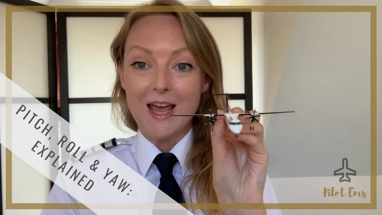
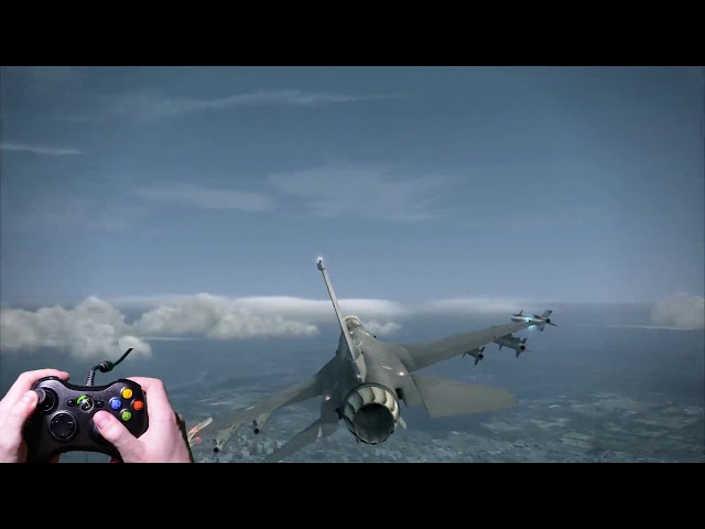
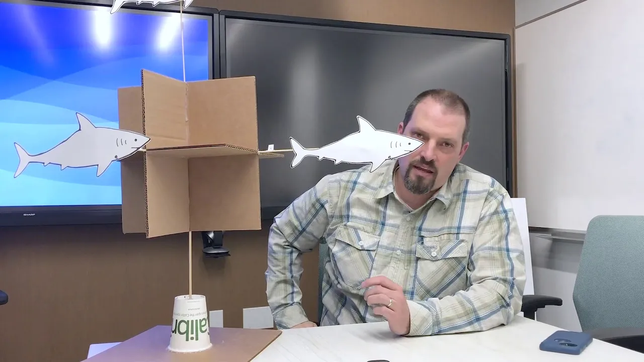











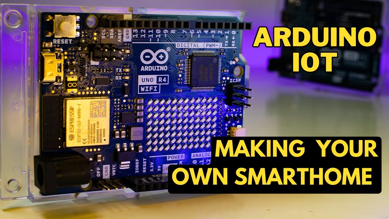
Tilt compensation mathematically projects the magnetometer readings onto a horizontal plane by using trigonometric functions (sine and cosine) of the roll and pitch angles, allowing accurate yaw/heading calculations even when the device is not level. The compensated values are calculated as: X_comp = X_cal × cos(pitch_rad) - Y_cal × sin(roll_rad) × sin(pitch_rad) - Z_cal × cos(roll_rad) × sin(pitch_rad), and Y_comp = Y_cal × cos(roll_rad) - Z_cal × sin(roll_rad), where X_cal, Y_cal, and Z_cal are the calibrated magnetometer readings.
Arduino Uno R4 WiFi: Tilt Compensated Compass Tutorial
Added:Basic Arduino programming proficiency, including code structure (setup/loop), using external libraries, and serial monitoring.
Understanding of the I2C communication protocol, which is essential for interfacing the Arduino Uno R4 with the GY-87 IMU.
Fundamental concepts of Inertial Measurement Units (IMUs), specifically how accelerometers, gyroscopes, and magnetometers function.
Basic trigonometry and 3D coordinate geometry, particularly the concepts of pitch, roll, yaw, and spatial orientation.
Exploring advanced sensor fusion algorithms, such as the Kalman Filter or Madgwick Filter, for more robust noise reduction.
Learning magnetometer calibration techniques to compensate for hard-iron and soft-iron magnetic distortions.
Integrating the tilt-compensated compass with a GPS module for autonomous robotic navigation and waypoint tracking.
Utilizing the Arduino Uno R4's onboard WiFi to transmit real-time telemetry and orientation data to an IoT dashboard or cloud service.
1.7K views65likes32:29Original Release: 2025-11-13
Hello guys, this is Paul McCarter with topteboy.com and we're here today with episode number 95 and our incredible new tutorial series where you're learning how to think like an engineer using the Arduino Uno R4 Wi-Fi. What I will need you to do is pour yourself a nice tall glass of ice cold coffee.
That would be straight up black coffee poured over ice. No sugar, no sweeteners, none needed. And as you're pouring your coffee, as always, I want to give a shout out to our friends over at Sunfounder.
Sunfounder is actually sponsoring this most excellent series of video lessons.
And in this class, we will be using the Sunfounder Elite Explorer Kit. Now, hopefully most of you guys already have your gear, but if you don't, take a look down below in the description. There is a link over to Amazon and you can hop on over there and pick your kit up. And believe me, your life and my life are going to be a whole lot easier if we are working on identical hardware. But enough of this shameless self-promotion.
Let's jump in and talk about what I am going to teach you today. And what I'm going to do is I'm going to teach you how to do tilt compensation on your digital compass that we've been working on in the last five or six lessons. What does tilt compensation means? It means that we want to be able to get an accurate reading from our compass independent of what pitch or roll we're at. So that is going to be what I am going to show you today. So, let me get out of your way and let me come over here and I'm going to ask you guys to go to the most excellent www.toptechboy.com.
We want to start off today, the same place that we ended up with last week.
And so, what I need you to do is use this happy little search icon and search on something like high-performance roll, pitch, and yaw values from the GY87 IMU.
You'll come to this page and you can see here we've got the schematic of our GY87 IMU module hooked up to our Arduino R4 Wi-Fi and this is the code that we ended up with last week and it calculates roll pitch and yaw using complimementaryary filters. So we end up with a result that is not subject to noise and vibration, has very low drift, responds very quickly, and maintains very accurate readings. And so we've gone through a number of lessons to get to that point.
There is uh one yet thing that we need to do, and we need to get it to work when we are not sitting perfectly flat.
That's what I'm going to show you how to do today. Now, as you get this code, you can come up here and click on this double little uh page icon and copy it.
But I need to remind you that these numbers are my calibration numbers. You don't use my calibration numbers. You use your calibration numbers for your GY87 module. Now, if you've been taking this class, you've already calibrated your sensor because we did that last week. If you if you're just a driveby shooter jumping into this lesson, you need to go back to lesson number 93 and you can get there on the website. You'll search on ultimate 9-axis program for easily and accurately calibrating your 9-axis IMU. you watch this video and I'll show you how to calibrate your device and I've got code here that takes the raw measurements and then I've got code here that will go in and help you do the calibration. So, if you haven't done this, you really do need to do lesson number 93 which you find here before you jump into to today's lesson.
But for the rest of you guys, you've already done that and you have your calibration parameters here. And so what we can do is just start with the rest of the code here. And now we're going to go to a fresh new Arduino IDE. I'm going to paste into that IDE. And now let's download that code. And what we should end up with is we should end up with something that is showing a very precise calculation for roll, pitch, and yaw.
Okay, looks good. Looks good.
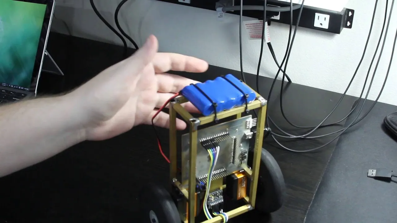
So, let's see if this thing works. What I'll do is I'll come here where you can see my little project here. I'm pointing roughly north, not perfectly north, but roughly north. And then I just remind you that for our orientation we call this the front. We call this the front of our device. And so X the positive X is the front. And then this is the left and this is the right. And so X forward is the front of our imaginary airplane or SUV or or whatever we have this thing on. [snorts] Okay. So now let's see if things are still working. So we're going to come up here. You can't see that. We're going to come up here to turn on the serial plotter and hopefully that will pop up.
Yep, we got that. And then I'll come back over here where you can see what I'm doing. And let's get that a little bit better to north. Okay, that's a little bit more perfect. North. And then what I want you to see is uh the blue curve is the roll. And right this is roll. Okay, this is roll. And left side up, right side down, that is positive roll. And nose up is positive pitch.
Nose down is negative pitch. And we are sitting there with no roll, no pitch.
That makes sense because the thing is sitting flat. And we're pointing roughly north, which is reading a yaw of 0 degrees. If we come over and point east, you can see that we'll come up to about 90°.
If we come and we point south, it'll pop down to about - 180°. Let's see. Yep, there it is. About - 180°. And then I think if we point west over here, we will see something like about 90°. And so we can see that that yaw is working very nicely and very smoothly. If I pitch the nose up, right, this is the nose positive X. I pitch the nose up and you can see that I'm measuring pitch.
Nose down, negative pitch. I've got the right wing up, which is negative roll.
I've got the left wing up, which is positive roll. And we can see this thing is working very good, very smooth, very stable, no drift. And so that's where we left off. So why are we doing something else? Because there is still a problem.
And what I want you to see is let's see, maybe I can show it like this. Okay. So, here we are up at about 100°. Uh we're pointing a little bit more uh than east.
We're pointing a little bit past east.
Okay. You're looking at the green curve.
Now, watch my hands. I am not changing the yaw, but I'm going to roll. Okay. I am going to roll in the negative direction. Okay. I'm going to roll in the negative direction. And what is happening to the yaw? My yaw in real life is not changing, but that green curve is changing. The yaw is reporting incorrectly when I tilt. Let's see what happens if I go roll the other way. And in that case, it's kind of stable. But if I'm pointing north and I go pitch down. Okay, look at that. I'm going pitch down.
And then what happens? Look at that yaw.
I'm getting huge errors in the yaw. So what is this thing? It works perfectly as long as you are perfectly flat. But if you are not perfectly flat, then you start having errors. And it kind of the error it's always hard to know where it's going to show up because there's some places that you can tilt. Like I think that if I tilt this way, okay, I tilt this way and there's not so much error in the yaw. Okay, so it's kind of there's certain quadrants where the error gets really bad. So you got to kind of kind of pay attention to that.
But you can [clears throat] see that we're not getting accurate readings when we pitch or roll this thing. And so why is that? Well, let's look at this. I've got X X P facing forward. Okay. And let's say that I am going to put a pitch on this. Okay. Now, when I put a pitch on this, is that X magnetometer still seeing the full magnetic vector?
Well, the full magnetic vector, let's say that it's coming in horizontally. We know that we all have different inclinations. But just to understand the problem, if this is the magnetic vector and then I rotate my project, this X magnetometer is no longer seeing that full magnetic vector. And so let let me put it this way like we come over here.
How do we calculate the yaw? Okay, how do we calculate the yaw? The yaw is the y mag the arc tan of the y magnetometer divided by the x magnetometer.
So if the y or the x value changes the reported yaw changes. Well here let's say I'm lined up with the magnetic vector. Now I'm not lined up. So I'm going to read a different x value. And as I read a different x value, this term changes and therefore this term changes. Okay. So do you see what the problem is? So how are we going to solve this problem? The way we are going to solve this problem is to mathematically trigonometrically we are going to untilt the sensor. So if I am reading an X value on the magnetometer as I'm tilted, I need to mathematically calculate what X value would I be reading if I was not tilted.
I have to through calculation until the sensor. And similarly, if I'm pitched, I have to unpitch it mathematically.
So what do I need to do? I need to come up with kind of a compensated value of the magnetometer in the Y and the magnetometer in the X where I mathematically until that make sense. I hope it does. Okay, so let's come in here and let's [clears throat] jump in and let's see if we can do some of this coding. Now, you're probably wondering, why do I not just go over to the sketch pad and show you the triangles and show you that it's going to be, you know, x values times a cosine of something, y values times a sign of something, how we're going to project that tilted reading onto a theoretical flat plane. Well, the problem is it's very hard to draw in three dimensions. And you can see the trigonometry gets a little tricky if I have a pitch and a roll at the same time. It becomes kind of three-dimensional trigonometry and it's not just a simple triangle that I can draw. Now, if you guys want to dive dig deeper into this, there's some uh there's some data sheets that come with some of these uh uh IMU modules that'll go into this in great depth. But what I want to do is I want to kind of just move on and show you what the right equations are. And then if you guys want to dig in deeper, you can. Okay. Does that make sense? All right. I hope it does. So, what we're going to do is I'm going to need to come up with a new my cal my ycal and mxal. Okay. And I'm going to do this here. All right. Now before I do that though you I'm going to be doing signs and cosiness on the rolls and pitches. Okay that we've already calculated. We already have the rolls and pitches. And I think the other thing that I'm going to do is uh yeah I'll I'll do that in a minute. But I'm going to I'm going to have to uh right now our rolls and pitches are in degrees. And what does Arduino want? If it's going to do a sign or a cosine, it is going to want to have things in radians. So I need to get a roll radians and I need to get a pitch radians. So what I'm going to do is I'm going to say the roll compens uh uh with the complimentary filter. I'm taking the roll with the complimentary filter applied and I'm going to convert it to radians. And that is going to be the roll with the compensation filter that we have. Okay. And then I'm going to multiply by pi and divide by 180. And now I have the compensated roll in radians. Hopefully that makes sense.
We've done a lot of this before. And similarly the pitch with the complimentary filter in radians is going to be equal to the pitch with the complimentary filter times pi divided [clears throat] by 180. Okay. So now we have our roll and our pitch comp uh complimentary filtered in radians.
That's what we needed. Now what [clears throat] I need to do is I need to get the horizontal value of the magnetometer Y calibrated and the horizontal value of the magnetometer X calibrated. And let's do the Y first because it's a little bit easier. So I'm going to do the MX calH is going to be equal to something. But we're going to start with the Y. So my [clears throat] cal h for horizontal. So I'm creating that calculated flat. I am what I am until mathematically untilting the sensor. So I'm going to take my existing y value my cal. Okay. And I'm going to multiply it by the coine of the ro [clears throat] c rad. Okay. So I'm taking if I'm tilted in roll by roll rad I'm going to take the coine of that and then that's going to give me the magnitude of that component in the horizontal and hopefully [clears throat] that kind of makes sense. Now I've got to correct it because [clears throat] if you look at this right now where when I'm sitting flat really you would not have a Z component to the uh to the measurement if the magnetic vector is coming in horizontally. The Z is not going to be reading anything. But if all the sudden I come in and I roll this thing now Z is going to start seeing part of that magnetic vector. And so we have to put that into the process. We have to fold that into the process of dilting. Okay.
And so how do we do that? Well, we need to subtract off that value. And that value is M Z the new reading in the Z uh on the Z magnetometer and it is the calibrated reading and then we're going to multiply that not by the coine but by the sign of the roll complimentary filter in radians like that. Okay. So [snorts] now I have a magnetometer in the Yaxis calibrated that has now been flattened or unttilted and that is the one that I should use here h and also we're going to use the x value horizontal or until now [cough and clears throat] the first axis is easy whichever one you do first is easy but then the second one. You see the first one is easy because it's just a two-dimensional triangle. But if I roll and pitch, the second one is going to be more complicated because it becomes threedimensional trigonometry. And that's what happens on the X. And so this is going to be the m the measured in the x calibrated times cosine of the pitch compensated in radian. So this looks kind of the same, right? It's just the x is associated with pitch and the y is associated with with roll. And so this really you can see is very analogous to this. But now we have to fold in the three dimensions in the next two terms.
So what I'm going to do next is the next I've taken care of x. Now I've got to project the y onto the flat plane. And so I do that with uh the magnetometer y calibrated times the sign of what the roll with the complimentary filter in radians like that. And I better turn that thing off so you can see what I'm doing. Okay, so it's the y times the sign of the roll and also I have to put in the pitch sign pitch complimentary filter sign pitch complimentary filter in radians.
Okay, so that looks good. Roll sign roll sign pitch. That looks good.
And now [clears throat] I've got to unfold the Z. I've got to project that Z onto the flat plane. And that is going to be minus [clears throat] the magnetometer Z calibrated times the coine of the roll C in radians times the sign of the pitch C in radians like that.
Okay. So you take a look at it. This last term, make sure you get the last term right. The last [clears throat] term is minus mz * cosine roll c rad time sine pitch c rad. Let's look at the second term. Make sure that you got that. Notice that we're subtracting that term as well. Subtracting that term as well. [clears throat] minus the magnetometer and the Y uh calibrated times the sign of ROC CAD times the sign of pitch C rad. That looks good. And then take a careful look at this first term. First term is pretty easy because there's just one uh cosine function in there. Okay, that looks good. Now, what do I need to do? I need to take these four variables and I got to declare them. So I'm going to copy that just to make it a little easier. I'm going to come up to the top of the program and I'm going to declare those variables. So I'll say v and then why do I copy and paste? Just because it's easier than try to remember exactly what I called them. Okay, so here we go.
Here we go.
Okay. So, this is going to be a float.
This is going to be a float.
And these are going to be floats.
[clears throat] Okay. So what does this do? It takes the tilted reading for X and until it projects it on the XY plane. What does this do?
This takes the Y and untilts it and projects it on the XY plane. Okay.
Now, this jaw magnetometer is still the variable we're going to use. We're just going to calculate it with these flattened values. Okay. So, [snorts] now let's run this thing and see how many mistakes we made. All right.
Pitch C rad. What did I misspell [clears throat] pitch without a t? pit p I TC P I TC and also I copied and pasted it up here. So I'll have to put it up here. P IT TCH. All right. So you guys need to look at these two lines very carefully. Make sure that you got those in there right. You also want to make sure that you're using the same definitions I am. What are the definitions that I am? Nose up is a positive roll. X is the forward direction of the sensor. Uh nose up is a positive pitch. Nose down is a negative pitch. Uh left wing up is a positive roll. Left wing down is a negative roll.
Okay, so that's how I've defined things.
And for this equation to work, you've got to kind of be oriented in the same way. Now, there's one other little thing that we need to see. We can see here that uh the uh flattened uh magnetometer values depend on this uh pitch complimentary filter and the roll complimentary filter converted to rads which depends on roll C and pitch C, but we haven't calculated those yet. We calculate those down here. [snorts] And so what we want to do is we want to move them up so that we're using the values from the present loop and not from the last loop. And so we're going to cut these.
I hope that makes sense what I just said. You don't want to use an old and steel value. And so we're going to come up here and we're going to put them here. Okay.
So now this is calculated based on the fresh value of the complimentary filter on the roll and then therefore these are all fresh and then therefore this will be fresh. Okay, hope that makes sense.
[clears throat] I think maybe we're ready to try to run this thing now. So let's run it.
Kind of encouraging here, right? It's kind of encouraging. Here it comes.
And boom. Okay. So now let's call up our little graphic. Bring it over here. And let's see how we're doing. I want to resize this window a little bit so you'll see the whole thing. Okay. Now [clears throat] you see I am uh I am pointed north. Okay. I am pointed north and I am reading a yaw of zero degrees.
And so that's good. Now, where did we end up with our first big problem where we pitched nose down? So, I need you to watch that green curve as I'm pitching down. You see pitch changing as you would expect. But what is yaw doing?
Rock solid, right? Look at that. Rock solid on yaw.
[clears throat] Almost all the way to 90°. And now I'm going to pitch nose up.
up. You see the nose going up. What is green doing? Rock solid. Rock solid all the way up to 90. Okay, look at that.
So, we have that thing compensated, but we really need to check the other axises because you can make a mistake on those equations and they will actually they will actually almost work. They will actually almost work. Well, let's point north and let me just I'm going to Okay, look at that. Beautiful. So, what am I doing? I'm pointing north and I'm putting a negative roll. And that yaw is staying rock solid. Now, let me put a positive roll and the green isn't changing. So, I've checked the four things there. Now, let me turn it orthogonally.
And [snorts] now I am going to pitch nose up. You're watching green pitching nose up.
No changes. I'm going to pitch nose down. No changes. Now I'm going to roll like this. Green is staying rock solid.
I'm going to roll. And green is staying rock solid.
You see the thing is I'm not holding it perfectly still, but these things are really working rock solid. Let me try one more time to put that roll on there. Do you see how far I'm going? And that green is not moving at all. Okay. So, what have we done? We [clears throat] have compensated this compass to where now I get an accurate heading in the presence of roll of pitch and of roll. Okay. And even if I roll, okay, I've rolled and I pitch. Okay. And I'm still getting it there. I can roll and pitch and the thing is still working. Okay guys, this has been kind of a interesting and fun lesson. And I hope you guys see the importance of this because you want to be able to keep an accurate reading. Even if your off-wheel your your four-wheel drive, off-road vehicle is going up an incline or going down, you want the heading to remain uh remain accurate. And I think we've done a good job. I think we have that working and we're going to call it a success.
Okay. Now, there's one other thing. So, this is what your homework assignment is going to be. Okay. So, we've got tilt compensation. But there's a couple of things that I want to show you here. And one is that if I come this way, okay, I am going from north to east. And that is all wonderful. When I get over here to east, I'm at about 90°. That's right.
Okay. But I want you to see that if I come here and I'm pointing north and if I start pointing back to the west, I start getting a negative yaw. And so that's saying it's going from posit uh from 0 to 180 and from 0 to minus 180 to where traditionally a compass goes from 0 to 360. And so you want to correct that so that you are reporting 0 to 360 instead of plus and minus uh 180. Okay, so that's the first thing. Now, let me show you if let me see if I can show you the second thing. There's always going to be a place that you jump. Okay, there's always going to be a place that you jump.
Okay. So, do you see this is when I went from minus 180 to + 180 and it takes that long path. But what I want you to see is the problem is that it's applying the complimentary filter. So, it just doesn't go from minus 180 to + 180. It thinks, "Oh, that's a big change. I don't trust that." And if you have this connected to a display, what that's going to mean is is you're going around 0 to 360, 360 to 0ero. When you go over this point, the needle is going to take the long way around the compass. It's going to take the long way around the compass and it's going to do it slowly because it's looking at that complimentary filter. So what I want is I want you to go instead of from positive 180 to minus 180 I want you to go from 0 to 360.
Okay? And then when you go from and it's really probably 359. So you go from 0 to 359. When you go from 359 to 0ero, I want it to snap. Or from 0 to 359, I want it to snap because you don't want to sit on your graphic and watch that needle go the long way around. So at that one transition, you want to turn off the complimentary filter and you want to instantly make the transition from a few degrees positive to a few degrees negative. You don't want to go the long way around the compass. Okay, I hope that homework makes sense. Never fear. Next week I will show you that solution. I will show you my solution to that problem. You guys should be able to figure that out. And then the other thing that I should say is you can see that I have my little SSD306 on here. And so we're going to be adding that very soon. But you guys need to get this last thing taken care of where you don't have that going around slowly when you make the 0 to 360 transition. you to get that done. And then after we do that, then we're going to turn the SSD306 on. And then we're going to have a little portable device that we can go mobile on. We could print roll pitch and yaw. We'll do that to start with. But then what we want to do is we want to have some cool graphics on here where we get something that looks more like that graphic that I had a few weeks ago, lesson number 96, where we have kind of like that aircraft heads up display. So, we're going to do the best we can to get that on this itty bitty little tiny screen. Okay? And I hope you're having as much fun taking the class as I am making it. It's at this point in the lesson that I always give a big shout out to you guys who are standing with me on Patreon. Without your support, I would not be able to continue to produce fresh new content, in-depth content every single week. So, big thank you to you guys. And uh as always, you know, share this video with other people because the world needs more people thinking like an engineer and fewer people sitting around watching silly cat videos. Paul McCarter with toptechboy.com. I will see you guys next week.
Up Next

63:11
Outdoor Robot Navigation with GPS Using ROS: Jackal Simulation
@TheConstruct
15.8K views•2018-04-07

58:25
MathWorks Virtual RoboSub Simulation Environment | Webinar 2026
@RoboNationInc
209 views•2026-03-10

48:53
Raspberry Pi Servo Control with Python: Step-by-Step PWM Tutorial
@paulmcwhorter
165.8K views•2015-06-02

25:22
Micromouse: The Fastest Maze-Solving Robots on Earth
@veritasium
23.5M views•2023-05-24
Related Study Plans & Knowledge Roadmaps
Structured learning paths in Robotics
robotics
Building Delta Robots: Kinematics & Pico
01Foundations of Delta Robots & Mechanical Design
02Electronics and Microcontroller Setup with Pi Pico
03Delta Robot Kinematics and Coordinate Math
+ 3 more learning modules
65h6 modules
Explore Roadmap
robotics
Building Ballbots: Dynamics, Kalman & LQR
01Embedded Electronics & Omniwheel Actuation
02Ballbot Kinematics & Rigid Body Dynamics
03IMU Sensors & Kalman Filter State Estimation
+ 2 more learning modules
42h5 modules
Explore Roadmap
robotics
Micromouse: Hardware, PID Control & Flood-Fill
01Electronics & Teensy Microcontroller Basics
02Sensors and Actuators: Motors, Encoders & IR
03Precision Movement: Implementing PID Control
+ 2 more learning modules
35h5 modules
Explore Roadmap
robotics
CDPR: Kinematics, Arduino & Winch Control
01Foundations of Arduino & Basic Electronics
02Stepper Motors and Winch Mechanics
03Kinematics of 2D Cable-Driven Robots
+ 2 more learning modules
28h5 modules
Explore Roadmap