







![[Introduction to Computer Vision] 2. Image Formation (1)](https://i.ytimg.com/vi_webp/wj-LdU92Wv8/maxresdefault.webp)














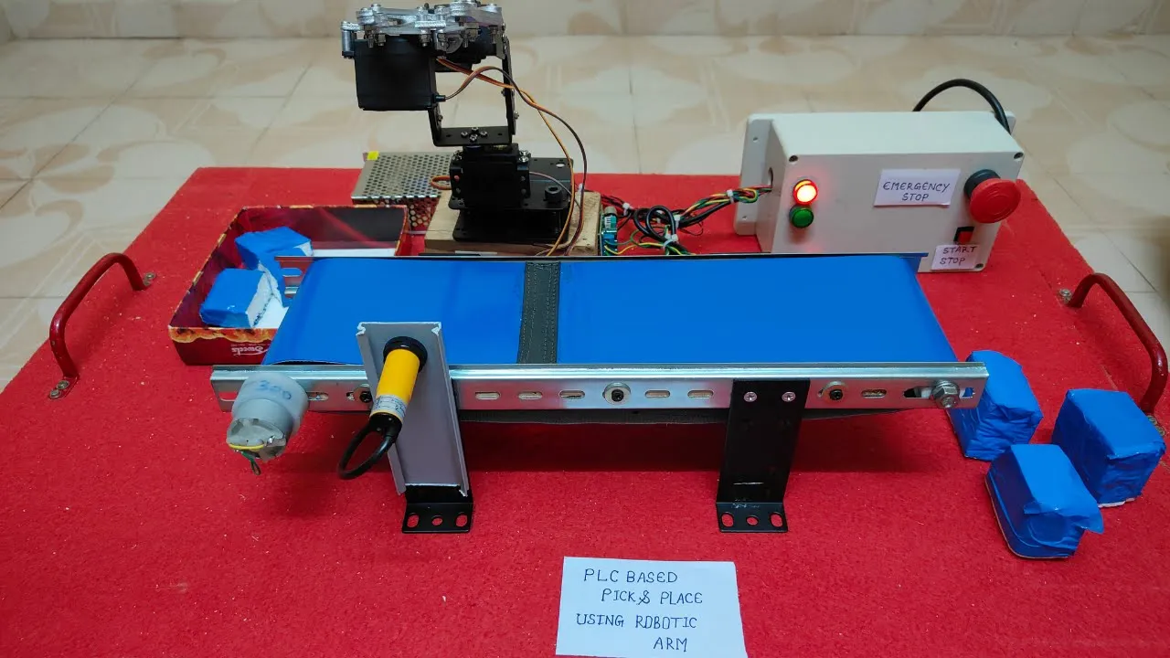

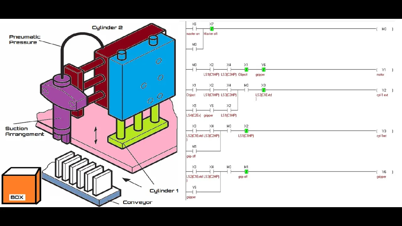
A vision-guided pick-and-place robot can be constructed by integrating a Pixy2 camera (which uses blob detection to identify objects of uniform color) with a Dobot Magician robotic arm, where the Arduino Mega serves as the central controller that processes camera data, performs coordinate transformation through a calibration routine, and executes pick-and-place operations using either a gripper or vacuum cup; the calibration process involves establishing a mathematical relationship between the camera's coordinate system and the robot's coordinate system by finding three reference points and calculating scaling, rotation, and translation parameters.
Machine Vision Pick-and-Place Robot with Pixy2 and Dobot Magician
Added:Basic Arduino programming, including familiarity with C/C++ syntax, installing libraries, and utilizing the Arduino IDE.
Fundamental concepts of robotics, specifically Cartesian coordinate systems (X,Y,Z axes) and basic robotic arm kinematics.
Basic computer vision concepts, such as color signature detection, thresholding, and mapping image sensor coordinates to real-world coordinates.
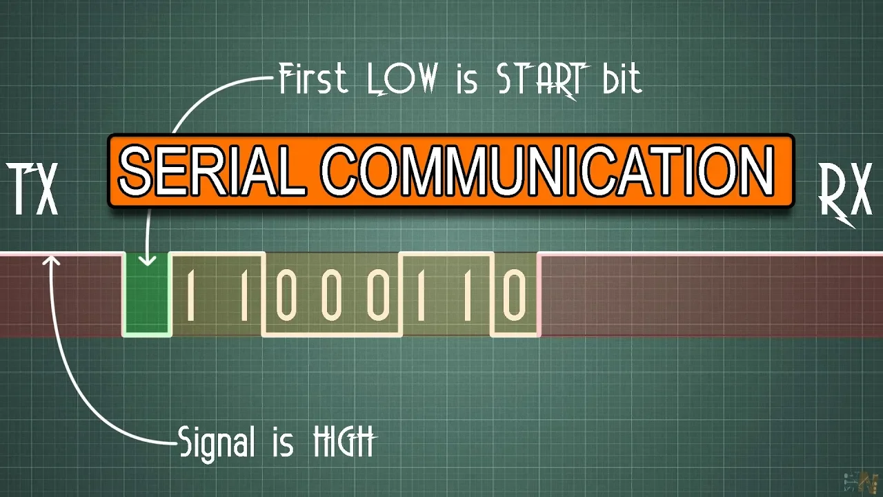
Hardware communication protocols such as I2C, SPI, or Serial (UART) for interfacing microcontrollers with external sensors and controllers.
Advanced Computer Vision utilizing OpenCV and deep learning framework models (such as YOLO) for complex feature-based object recognition instead of simple color tracking.
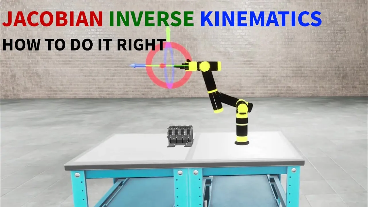
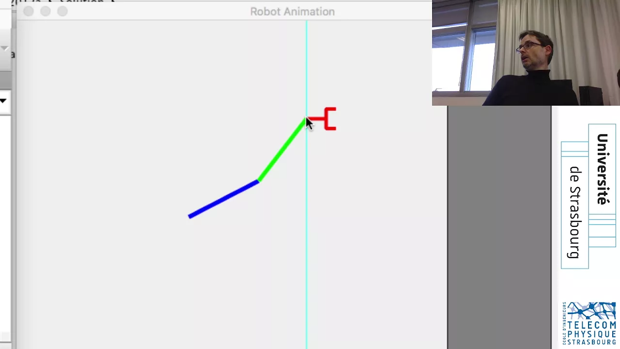
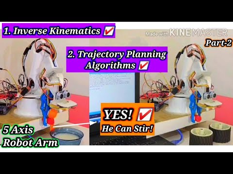
Inverse kinematics and trajectory planning algorithms to achieve smoother, more efficient, and collision-free robotic arm paths.
Integration with the Robot Operating System (ROS / ROS2) to manage complex hardware-software abstraction and coordinate multiple sensors.
Industrial automation protocols and PLC (Programmable Logic Controller) integration to scale pick-and-place systems for real-world manufacturing lines and conveyor systems.
77.8K views1.3Klikes20:12Original Release: 2019-10-02
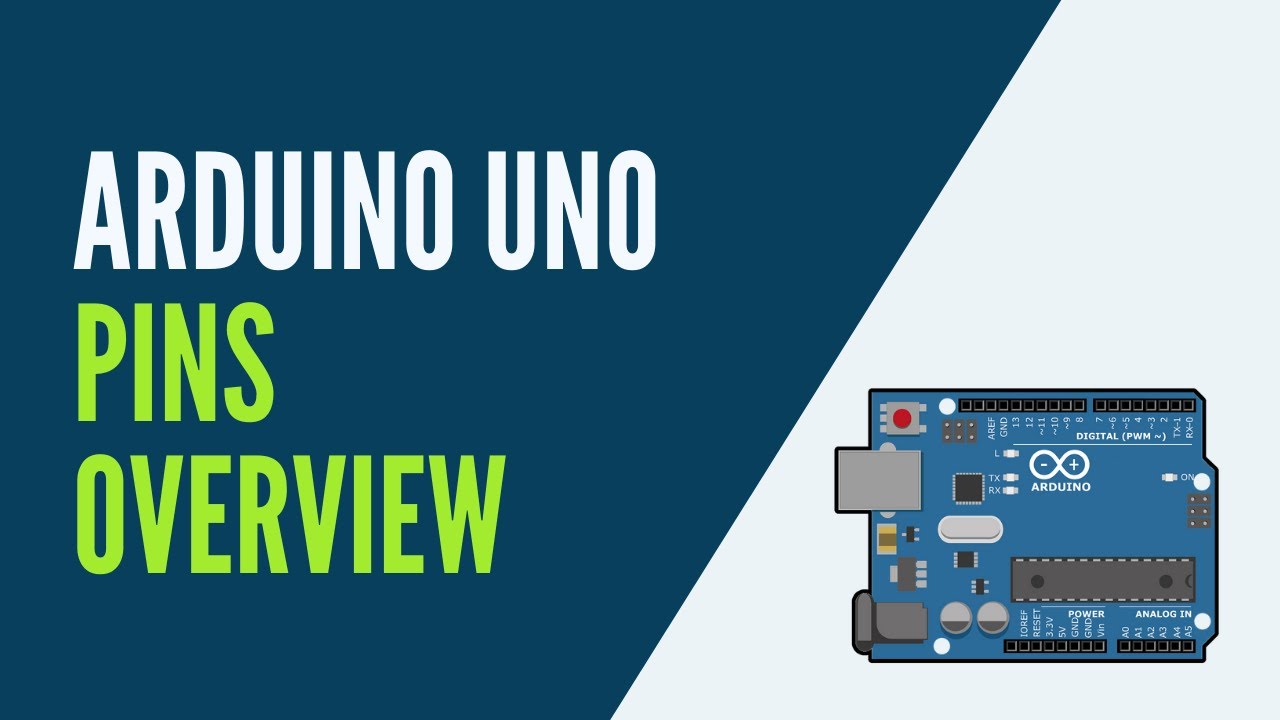
robotic arms and vision systems are used in many modern production lines in this video I will show you how to make your own pick-and-place robot which can identify parts automatically and place them in the right location since I am NOT a robotics specialist I learned a lot of new things while working on this project I hope there's some useful information for you in there as well I will show you how I use the pixie 2 module for pick-and-place tasks on simple cylinder shaped parts using the do bot magician robotic arm when Arduino mega is used to tie everything together and to make the arm perform tasks based on the input from the pixie 2 camera I will go through the entire projects in different sections starting with how to connect the pixie 2 and the do bot to the Arduino the camera position and the mounting brackets the camera settings and lighting the calibration routine the Arduino programming followed by a pick-and-place demo with the gripper and a pick a place demo with a vacuum cup recently I found an article on the pixie 2 vision module the 2018 upgrades to the original pixie camera launched on Kickstarter in 2013 pixie 2 is a nifty camera module with built in part detection which can track objects at 60 frames per second it does not have the resolution feature recognition or any of the other fancy features of professional vision systems but with the features that it does have it's perfectly capable of handling less demanding object detection tasks the object detection on the pixie 2 is based on blob detection where something is recognized as an object when enough pixels of a similar predefined color are found any image objects need to have a more or less uniform color across a part which differs significantly from its surroundings the pixie 2 does not recognize the shape of an object so part identification based on geometry or finding the angle at which a part is rotated is not possible okay so let's start with how to connect the pixie to and do bot to the Arduino in this project the pixie - and a do pod magician are connected to an Arduino mega which contains a program for controlling the pick-and-place routines the pixie 2 is connected to the I squared C bus on the center of their doing aboard the pixie can be connected using the supplied flat cable however since it's too short for this application I made a new cable at the desired length flat cable connectors and the cable itself were purchased from a local electronics store since I do not have a crimping tool I used a pair of pipe wrench pliers to crimp the connector which is not advisable but it works just a quick check with the multimeter to see if all connections are made properly and we're ready for the next step and now see these shields is placed onto the Arduino board with some female circuit heifers in between to clear serial connector below the board the ground pin on the do board is connected to one of the ground pins on the Arduino the RX and th pins from the do bot are connected to the TX and rx pins on the Arduino in this case wins 18 and 19 o years I've considered two options for where to position the camera either in a stationary setup where the camera is mounted on a separate stand or with the camera fixed near the end effector on the arm itself both options have their pros and cons the benefits of a stationary setup is that the camera can register parts at the same time the robust performing pick-and-place operations this option leads to the quickest cycle times and may therefore be the best option for industrial use in a fixed production line setup the drawback however is that the camera is separated from the robot arm and therefore needs to be recalibrated if either of the two are moved to a different position this is the reason why I chose to mount the camera directly onto the robot arm the position of the camera now only needs to be calibrated once and still valid when the arm is picked up and moved to a different location I've designed the camera mounting feature which is used to fix the pixi to the front of the robot arm the part was designed in fusion 360 there are a couple of requirements that lead to the current design the camera should be close to the end effector while making sure that it's at a position where the gripper or restriction cup did not block the view of the camera in order to align the field of view of the camera as well as possible with the movement range of the arm I decided to place the camera on the side of the end effector instead of mounting it directly in front the camera is also slightly rotated since the arm is also rotated at a certain angle when the camera is directly above the area where the parts are located this angle does not have to be exact it's only intended to get as much as possible of the picking area into the image which would not be possible if the image was tilted any residual angle of the image will be taken care of automatically in a calibration routine procedure a picture of the pixi 2 module was imported into the fusion 360 module for visualization purposes and more importantly to transfer the location of the mounting holes to the picture since the module is very light it's sufficient to use only two of the available mounting holes standard m3 screws are used to fix the module and/or screw directly into the non-threaded undersized dolls [Music] [Music] [Music] with the camera in place is time to have a look at the calibration routine the calibration routine basically makes it possible to transform XY locations in the coordinate system of the pixie camera to the coordinate system of the dubas so each time a part is found by the camera its location is transformed to the coordinate system of the robot arm so it's able to pick up a part several factors need to be taken into account when trying to transform the coordinates the routine I'm about to describe takes care of scaling in x and y direction rotation and translation to keep things simple I did not take into account skewed coordinates or lens distortions I used some basic trigonometry to perform the transformations first the camera is moved to a position at a height where the entire work area is in view a routine is performed where the camera searches for three calibration dots one representing the origin of the coordinate system and the other two points at a random location at the x and y axis the distance between the points is not relevant only that they describe two intersecting lines which are perpendicular to each other the location of the calibration dots are stored in the EEPROM of the Arduino controller so they can be used later even after turning the system off let's call a coordinate system of the pixie system one second part of the calibration routine is to move the robot on physically to each of the calibration points as accurately as possible [Music] these locations are also recorded in the EEPROM we will call this coordinate system system 2 we now have all the data we need to transform coordinates from the first coordinate system to a corresponding location in the second coordinate system this is performed as follows first the angle of each system is calculated as well as the scale of the x and y axis and the distance between the origins of both systems the coordinate is moved in x and y by the same distance as the origin location of system 1 coordinate system one is then rotated to make X horizontal and Y vertical the x and y taxis are skilled to match the x and y axis of system to another rotation is made matching the angle of system to the coordinate system is then translated in x and y by the same distance as the origin location of system two when all of this is done we should have found the location of the part in the coordinate system of the dubov which is required to send the robot arm to the right location now let's have a look at the Arduino programming for the pixie to a library has been made available for the other we know allowing it to be integrated easily into Arduino projects the library for the pixie can be downloaded from the pixie websites I'll put a link in the description below and can be installed in the arduino ide by selecting the sketch menu then include library and add ship library doing this also makes pixie demo sketch is available under the file menu for the do bot no library needs to be installed the Arduino program for this project consists of three main sections which are also covered under 3 menu items on the arduino LCD shield i will go quickly through each menu item if you would like to have more details on the underlying arduino code you can download to the program from our website obtain fab.com link in the description below i left a lot of comments in the Arduino program but if you still have some questions please leave them in the comment section the three menu items bar code menu for manually operating the robot on a run menu in which the automatic cycle can be activated in the settings menu for calibrating the camera setting positions for drop locations etc I have to admit the menu system is a bit primitive but I focused more on getting the assistant to work then improving the user interface let's go through menu after starting the system come screen appears during startup also all previously stored data is read from the EEPROM after pressing any key you end up in the first menu item which is the joke menu this allows the user to set a job increment from point 1 millimeter to 20 millimeters the robot arm is moved with the selected increment anytime the up or down keys are pressed the current access is displayed on the bottom right including its position pressing the right arrow button changes the axis all four axis can be controlled x y and z for the movement of the arm and are for the rotation of the gripper the vac option allows the user to manually open or close the gripper or activate the vacuum for suction-cup depending on which one is selected menu 2 is for starting the automatic cycle which will be demonstrated later in the video in menu 3 the user can set the following parameters set the calibration position or move to the currently stored calibration position set or go to the sea down position which is the Z position which the parts were picked from the table set or go to the positions of calibration dots a B and C this is used in the calibration procedure set or go to the start position which is the initial pose of the arm after startup set or go to any of the drop-off locations start the calibration routine and selected the enter factor is a gripper or vacuum Cup for the gripper both vacuum and compressed air are used to operate it and for the vacuum Cup only vacuum is required now let's have a quick look at the camera settings and lighting the way parts are lit has a huge effect on how well the camera is able to find parts the parts may become overexposed when using too much light or the opposite the camera may not be able to recognize a color when the lighting conditions are too dim I found that there's not a lot of leeway for the lighting setup and I have to regularly change the camera settings if the amount of ambient light is changing for example at a different time today in order to get a correct exposure and visibility of the part you can play around with the background color of the table the type of light source the position and angle of the light source and probably a lot of other factors the picture itself also has a built-in LED to illuminate the scene which could be another option I've gotten the best results during daytime when just using incoming sunlight as a light source but your mileage may vary I will put a link in the description below to a very helpful article on lighting for machine vision systems there are a couple of settings in the pixie monitor software that can also greatly help to improve part detection one is camera brightness this sets the overall brightness level and can help better identify different colored parts for each signature there's also a setting called signature range set this for each color signature individually to prevent false positives while still picking up as much surface area of the part as possible go to settings camera on this tab you can choose whether the camera applies auto exposure and auto white balance on the same tab there's a setting called flicker avoidance enable this when using inner lighting this should eliminate the flickering effects however this makes the picture much brighter and could cause overexposure to counteract this turn down the light source until a good exposure is achieved now that we have everything set up let's look at a pick and place demo with the gripper followed by a demo with the vacuum Cup [Music] you may notice that the arm sometimes pauses between moves I've implemented delays in the automatic cycle since I was not able to read back the current position from the do both therefore I'm just waiting until a certain amount of time has passed to make sure the two bot has finished the previous move this is a pretty ugly solution of course there is a gap boss function available from do bot for reading back to precision but it wasn't able to make it work with the Arduino so if anyone knows how to do this please let me know in the comments thanks [Music] [Music] [Music] [Music] [Music] [Applause] [Music] [Music] [Applause] [Music]
Up Next

8:20
Color Sorting Robotic Arm with Servo Motors and Arduino
@roboticsandmechatronicsres2625
1.7K views•2020-08-25

58:25
MathWorks Virtual RoboSub Simulation Environment | Webinar 2026
@RoboNationInc
209 views•2026-03-10

11:04
How to Build a Self-Balancing Robot: Arduino Nano & MPU6050
@easytechzones
16.8K views•2022-03-09

25:22
Micromouse: The Fastest Maze-Solving Robots on Earth
@veritasium
23.5M views•2023-05-24
Related Study Plans & Knowledge Roadmaps
Structured learning paths in Robotics
robotics
Building Delta Robots: Kinematics & Pico
01Foundations of Delta Robots & Mechanical Design
02Electronics and Microcontroller Setup with Pi Pico
03Delta Robot Kinematics and Coordinate Math
+ 3 more learning modules
65h6 modules
Explore Roadmap
robotics
Building Ballbots: Dynamics, Kalman & LQR
01Embedded Electronics & Omniwheel Actuation
02Ballbot Kinematics & Rigid Body Dynamics
03IMU Sensors & Kalman Filter State Estimation
+ 2 more learning modules
42h5 modules
Explore Roadmap
robotics
Micromouse: Hardware, PID Control & Flood-Fill
01Electronics & Teensy Microcontroller Basics
02Sensors and Actuators: Motors, Encoders & IR
03Precision Movement: Implementing PID Control
+ 2 more learning modules
35h5 modules
Explore Roadmap
robotics
CDPR: Kinematics, Arduino & Winch Control
01Foundations of Arduino & Basic Electronics
02Stepper Motors and Winch Mechanics
03Kinematics of 2D Cable-Driven Robots
+ 2 more learning modules
28h5 modules
Explore Roadmap