The vapour compression refrigeration cycle consists of four main components: compressor, condenser, expansion device, and evaporator, which work together to transfer heat from a low-temperature source to a higher-temperature sink through the continuous circulation of refrigerant.
Refrigeration Cycle Explained | Vapour Compression Refrigeration Cycle
Added:Deep Dive
Basic principles of thermodynamics, specifically the concept of heat transfer and the Second Law of Thermodynamics.
|L16| 2nd Law of thermodynamics | Thermal Physics & Semiconductor Devices | bsc 2nd sem physics |
30.9K
The Second Law of Thermodynamics establishes fundamental principles about heat transfer and energy conversion. Heat naturally flows from hot to cold objects, and this direction cannot be reversed without external work. The Kelvin-Planck statement states that no heat engine can convert all absorbed heat into work without any external agency or other effect. This means some heat must always be rejected to a cold reservoir, making 100% efficient engines impossible. Refrigerators demonstrate the reverse principle, requiring external electrical work to transfer heat from cold to hot. These principles explain why perpetual motion machines are impossible and form the foundation for understanding thermal systems and energy conversion efficiency.
Click to watch →

Physics principles that shape our everyday lives| RAS Mains 2023 |Science & Technology
1.3K
The Second Law states: (1) Kelvin-Planck: No device can convert all heat from a single reservoir into work. (2) Clausius: Heat cannot spontaneously flow from cold to hot body. Heat transfer occurs by: (1) Conduction - through stationary material (solids), (2) Convection - through fluid movement, (3) Radiation - through electromagnetic waves (can occur in vacuum).
Click to watch →

Numerical 2 on Second Law of Thermodynamics - Second Law of Thermodynamics - Thermodynamics
1K
The Second Law of Thermodynamics states that heat naturally flows from a higher temperature body to a lower temperature body, and this process is irreversible; for example, when a hot object at 122°C is placed in contact with a cooler object at 20°C, heat will transfer from the hotter to the cooler object until thermal equilibrium is reached.
Click to watch →

3º Simulado Especial Petrobras - Técnico de Operação - Pré-Edital - Correção
1.1K
Heat transfer mechanisms: conduction transfers heat through molecular vibration in solids. Convection transfers heat through fluid motion. Radiation transfers heat through electromagnetic waves and does not require a medium. Dark surfaces have higher emissivity and absorb more radiation. Second Law of Thermodynamics: heat spontaneously flows from hot to cold bodies, not vice versa. Natural processes increase the total entropy of the universe. Processes that would decrease entropy are not spontaneous without external work input.
Click to watch →

2/محور الديناميك الحرارية: الفهم الصحيح لكمية الحرارة Q المكتسبة والمفقودة (الجزء الثاني)
4.7K
Thermodynamics is based on four fundamental points: change in internal energy, work, heat quantity, and change in enthalpy. The first law states that internal energy change includes both work and heat. Heat transfer occurs when a system exchanges energy with its surroundings. When a system absorbs heat, its temperature increases (positive ΔT), and the calculated heat value is positive. When a system releases heat, its temperature decreases (negative ΔT), and the calculated heat value is negative. When temperature remains constant, no heat transfer occurs (adiabatic or isolated systems). Heat always transfers from hotter to colder systems, with the cold object absorbing heat and the hot object releasing it.
Click to watch →
Deep Dive
The concept of phase change (latent heat), including how substances absorb heat during evaporation and release it during condensation.

IAS 2021 | Gurukul 2.0 | Geography by Sumit Rathi | Temperature| Part 2
32.9K
Latent heat is energy absorbed or released during phase changes without temperature change. Latent heat of vaporization is energy absorbed when liquid changes to gas, causing cooling. Latent heat of condensation is energy released when gas changes to liquid, causing warming. During evaporation, substances absorb energy from surroundings, which is why evaporation causes cooling. During condensation, substances release energy to surroundings, which is why condensation causes warming.
Click to watch →

MATTER IN OUR SURROUNDINGS in 1 Shot | FULL Chapter Coverage (Concepts + PYQs) | Class-9th Science
1.9M
State changes occur through heating/cooling: Melting (solid to liquid), Boiling (liquid to gas), Sublimation (solid to gas), Condensation (gas to liquid), Solidification (liquid to solid), Deposition (gas to solid). During heating, particles gain kinetic energy, move faster, overcome forces, spaces increase. During cooling, particles lose kinetic energy, move slower, forces increase, spaces decrease. Melting point (ice at 0°C), boiling point (water at 100°C). Latent heat of fusion (solid to liquid) and vaporization (liquid to gas) are absorbed during phase changes. Temperature remains constant during phase changes because heat is used for state change, not increasing kinetic energy. Gases liquefy under high pressure and low temperature. Sublimation examples: camphor, ammonium chloride, naphthalene, iodine. Evaporation is liquid changing to gas below boiling point. Factors: Surface area (more = faster), Temperature (higher = faster), Humidity (higher = slower), Wind speed (higher = faster). Evaporation causes cooling because liquid absorbs heat from surroundings. Desert coolers work better on hot, dry days. Evaporation is surface phenomenon, boiling is bulk phenomenon occurring only at boiling point.
Click to watch →

【2027共通テスト完全対応】4時間で極める地学基礎 無料テキスト付き!!
39.4K
Phase changes involve the absorption or release of latent heat: (1) Melting (solid to liquid) absorbs heat; (2) Freezing (liquid to solid) releases heat; (3) Vaporization (liquid to gas) absorbs heat; (4) Condensation (gas to liquid) releases heat; (5) Sublimation (solid to gas) absorbs heat; (6) Deposition (gas to solid) releases heat. Latent heat is the energy absorbed or released during phase changes without a change in temperature. This concept is important for understanding weather patterns, as phase changes of water release or absorb large amounts of energy that drive atmospheric circulation.
Click to watch →
Sustancias puras - Clase 5 Termodinámica
123.5K
Latent heat is the amount of energy absorbed or released during a phase change without temperature change. When a substance absorbs latent heat, it undergoes transformation: solid to liquid (melting/fusion) or liquid to gas (vaporization/evaporation). Conversely, when releasing latent heat, the substance changes from gas to liquid (condensation) or liquid to solid (freezing). For example, ice absorbs heat to melt into water, and boiling water absorbs heat to become steam.
Click to watch →

فيزياء الاول متوسط | الفصل الخامس ( التبخير والغليان ) محاضرة 3
93.5K
Phase changes include evaporation (liquid to gas), condensation (gas to liquid), and melting (solid to liquid). These are physical changes without chemical property alteration. Latent heat of vaporization is the heat required to convert 1 kg of liquid to gas at boiling point. Latent heat of fusion is the heat required to convert 1 kg of solid to liquid at melting point. During phase changes, temperature remains constant despite heat transfer.
Click to watch →
Deep Dive
The relationship between pressure and temperature, particularly how changing the pressure of a fluid alters its boiling point.

#03 Reversible & Irreversible Process | Engg.Thermodynamics | Crash Course (English) | Varun Sir
3.6K
The boiling point temperature is a function of pressure. Even a slight change in pressure causes changes in the boiling point temperature. When pressure increases, more energy must be provided to separate molecules, resulting in an increase in boiling point temperature. This relationship is fundamental to understanding phase transitions and thermodynamic systems.
Click to watch →

Complete Physics Rapid Revision | Complete Physics | 71st BPSC Prelims 2025 | @YouTube
43.9K
The boiling point of a liquid increases with increasing pressure and decreases with decreasing pressure. At standard atmospheric pressure (1 atm), water boils at 100°C. In a pressure cooker, higher pressure raises the boiling point above 100°C, allowing food to cook faster. At high altitudes, lower pressure lowers the boiling point.
Click to watch →

Properties of real fluids
256
Boiling point is directly dependent on pressure: increasing pressure raises boiling point while decreasing pressure lowers it. Volume change during boiling decreases significantly at higher pressures and increases substantially at lower pressures. The enthalpy of vaporization decreases with rising temperature—low-temperature boiling requires more energy than high-temperature boiling. At the critical point and above, no phase change occurs, eliminating the concept of boiling. These principles are essential for chemical engineers designing separation processes and understanding fluid behavior under varying conditions.
Click to watch →
Pump Cavitation & Net Positive Suction Head Basics I NPSH Derivation
78.7K
The boiling point of a liquid is directly related to pressure. Higher absolute pressure results in higher boiling temperatures, while lower pressure causes lower boiling points. For example, water boils at 100°C at 1.013 bar atmospheric pressure, but at 121°C when pressure increases to approximately 2.068 bar. Conversely, reducing pressure to 0.05 bar causes water to boil at only 32.9°C, demonstrating how pressure significantly affects boiling behavior.
Click to watch →

Pressure and its Measurement| Part-3| Fluid Mechanics| SSC JE 2022 |CIVIL ENGINEERING| Sandeep Jyani
27.8K
The boiling point of a liquid decreases when the pressure above it is reduced. When the pressure on the liquid surface is reduced to equal the vapor pressure of the liquid, boiling begins at that temperature. For example, at 20°C, if the vapor pressure is reduced to equal the pressure on the liquid surface, boiling will occur at 20°C. This is why food takes longer to cook at high altitudes where atmospheric pressure is lower.
Click to watch →
Deep Dive
Fundamental heat transfer mechanisms, such as conduction and convection, and how fluids absorb and reject thermal energy.
Conduction, Convection & Radiation
15.6K
Heat transfer occurs through three primary mechanisms: conduction, convection, and radiation. Conduction is the transfer of heat through direct molecular contact between solid surfaces, where faster-moving molecules in hotter objects transfer kinetic energy to slower molecules in cooler objects. This is why touching a hot stove causes burns. Convection differs because it occurs within fluids (liquids and vapors) where molecules are free to move, carrying heat energy with them as they circulate. Opening a refrigerator door demonstrates convection as warm air rushes in while cooler air escapes. Both mechanisms require physical contact or fluid movement to transfer heat energy.
Click to watch →
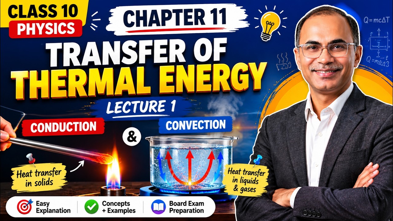
10th Physics Chapter 11 Lecture 1 | Conduction and Convection | Transfer of Thermal Energy
176
Heat transfer is the process by which thermal energy moves from hot to cold objects until equilibrium is reached. Conduction transfers heat through solids via vibrating molecules colliding without material movement. Metals conduct faster than non-metals due to free electrons acting as 'thermal superhighways.' Convection transfers heat through fluids via actual fluid movement: warm fluid rises (lower density) while cool fluid sinks (higher density). This creates continuous circular currents. Practical applications include placing heaters at room bottoms and air conditioners at tops.
Click to watch →

Física2-Aula15-Condução térmica (Prof.Wellington)
456
Heat transfer occurs through three fundamental mechanisms: (1) Conduction - heat transfer through stationary materials via molecular vibration, predominant in solids especially metals; (2) Convection - heat transfer through fluid movement driven by density differences, occurring in liquids and gases; (3) Radiation - heat transfer through electromagnetic waves (infrared) without requiring a medium, traveling at the speed of light. These mechanisms can occur simultaneously in the same situation.
Click to watch →

Modes of Heat Transfer in telugu l conduction , convection,radiation l Holistic telugu channel l HT
22.8K
Conduction occurs through two mechanisms: lattice vibration (where atoms/molecules vibrate and transfer energy to adjacent particles) and free electron transport (where free electrons move and carry thermal energy). Convection, occurring only in fluids, involves heat transfer through fluid mixing and depends on fluid properties rather than surface material properties. Convection is classified into natural convection (driven by temperature-induced density changes) and forced convection (driven by external sources like fans or pumps). Both modes require physical medium for heat transfer, with conduction working in solids and convection working in fluids.
Click to watch →

TRANSMISSÃO DE CALOR: condução, convecção e irradiação | Cortes dos Aulões do Enem | Física
5.6K
Heat is thermal energy in transit that flows from higher to lower temperature bodies until thermal equilibrium is reached. Temperature measures molecular agitation. Heat transfers through three mechanisms: conduction (particle-to-particle energy transfer without matter movement, predominant in solids), and convection (fluid movement driven by density changes from heating/cooling). When heated, fluids expand and become less dense, rising; when cooled, they contract and become denser, sinking. This creates convection currents. Practical applications include air conditioner placement (top of rooms) and refrigerator design (freezer at top).
Click to watch →
Prerequisite Knowledge
- Concept 01Basic principles of thermodynamics, specifically the concept of heat transfer and the Second Law of Thermodynamics.
- Concept 02The concept of phase change (latent heat), including how substances absorb heat during evaporation and release it during condensation.
- Concept 03The relationship between pressure and temperature, particularly how changing the pressure of a fluid alters its boiling point.
- Concept 04Fundamental heat transfer mechanisms, such as conduction and convection, and how fluids absorb and reject thermal energy.
Subsequent Learning
- Step 01Analyzing the vapor compression cycle on a Pressure-Enthalpy (p-h) diagram to calculate the Coefficient of Performance (COP).
- Step 02Understanding the properties and environmental impacts of different refrigerants (e.g., HCFCs, HFCs, and natural refrigerants like CO2 and Ammonia).
- Step 03Exploring advanced refrigeration cycles, including multi-stage compression, cascade systems, and vapor absorption refrigeration.
- Step 04Practical HVAC troubleshooting and component selection, such as sizing expansion valves, compressors, and heat exchangers for specific thermal loads.
Core parts
Cycle flow
Pressure state
Heat transfer
Refrigerant role
Low temp state
Cycle repeat
Core parts
0:04Playing Section
- 1
Identifies compressor, condenser, and expansion valve.
- 2
Lists evaporator as the fourth main component.
Thermally-Driven and Solid-State Cooling Alternatives
While the Vapor Compression Refrigeration Cycle (VCRC) is the dominant cooling technology, it faces criticism for its high electricity consumption and reliance on environmentally harmful chemical refrigerants (like HFCs). To broaden their perspective, students should explore alternative thermodynamic systems that bypass mechanical compression. The Vapor Absorption Refrigeration Cycle replaces the electric compressor with a heat-driven process, utilizing waste heat or solar energy to drive cooling. Additionally, emerging technologies like Thermoelectric and Magnetocaloric (Solid-State) Refrigeration eliminate chemical refrigerants and moving parts entirely, using electrical currents or magnetic fields to transfer heat. Exploring these alternatives highlights that refrigeration can be achieved without the high mechanical work and ecological drawbacks inherent to the standard compression cycle.
Deep Dive
Analyzing the vapor compression cycle on a Pressure-Enthalpy (p-h) diagram to calculate the Coefficient of Performance (COP).
SSC JE 2025 Mechanical Last 20 Days Crash Course | RAC | SSCJE Mechanical classes
16.4K
This section explains the VCRS processes on the P-H diagram and the COP calculation. On the P-H diagram: 1-2 is Isentropic Compression (vertical line upward), 2-3 is Constant Pressure Heat Rejection (horizontal line leftward), 3-4 is Isenthalpic Expansion (vertical line downward), and 4-1 is Constant Pressure Heat Addition (horizontal line rightward). The COP for VCRS is calculated as: COP = Refrigeration Effect / Compressor Work Input = (h1 - h4) / (h2 - h1). The refrigeration effect is the heat extracted from the evaporator, and compressor work is the work input to the compressor.
Click to watch →
Actual Vapour Compression Cycle-1
98.6K
The pressure-enthalpy (PH) diagram provides an alternative visualization of vapor compression cycles compared to temperature-entropy diagrams. On PH diagrams, constant pressure lines are horizontal, constant entropy lines are curved, and constant enthalpy lines are vertical. The complete cycle (compression, condensation, expansion, evaporation) can be plotted by following these lines. Superheating shifts the compression start point rightward, while subcooling shifts the expansion endpoint leftward. PH diagrams allow easier calculation of COP through direct enthalpy value reading.
Click to watch →

Fundamentals And Calculation Of Vapour Compression Cycle For Msbte & Mumbai University students #DG
139
The refrigerating effect (Q) is the heat absorbed in the evaporator, calculated as Q = h1 - h4, where h1 is enthalpy at evaporator exit and h4 is enthalpy at evaporator inlet. The Coefficient of Performance (COP) measures system efficiency: COP = (h1 - h4) / (h2 - h1), representing cooling effect per unit work input. For an ideal vapour compression cycle problem: draw the P-H diagram with saturation lines, mark the four key points (dry saturated vapour at evaporator exit, superheated vapour at compressor exit, saturated liquid at condenser exit, mixture at evaporator inlet), and use given enthalpy values to calculate COP. Example: with h1 = 268 kJ/kg, h2 = 312 kJ/kg, h3 = 124 kJ/kg, and h4 = h3 = 124 kJ/kg, COP = (268 - 124) / (312 - 268) = 3.27.
Click to watch →

Lec-18 Refrigeration Vapour Compression Cycle
33.9K
The pressure-enthalpy (p-h) diagram is the conventional representation for refrigeration cycle analysis. Key quantities are directly visualized: work input (H2-H1), refrigeration effect (H1-H4), and heating effect (H2-H4). For refrigeration: COP_R = (H1-H4)/(H2-H1); for heat pumps: COP_HP = (H2-H4)/(H2-H1). Since H2-H4 > H2-H1, heat pump COP always exceeds 1. This represents conversion of high-quality work to lower-quality thermal energy at moderate temperatures, consistent with second law principles. The diagram enables quick performance assessment and optimization.
Click to watch →

Vapour Compression Refrigeration Cycle in Hindi, Diagram, Processes, TS, Ph Diagram, COP VCRS Cycle
73.3K
The P-H (Pressure-Enthalpy) diagram for the vapour compression cycle shows: (1) Process 1-2 (Compression): Isentropic compression where enthalpy increases as work is added to the compressor, moving from saturated vapor to superheated vapor. (2) Process 2-3 (Condensation): Constant pressure heat rejection where enthalpy decreases as heat is rejected, moving from superheated vapor to saturated liquid. (3) Process 3-4 (Throttling): Irreversible expansion where enthalpy remains constant but entropy increases, causing temperature to drop. (4) Process 4-1 (Evaporation): Constant pressure heat absorption where enthalpy increases as heat is absorbed, moving from saturated liquid to saturated vapor.
Click to watch →
Deep Dive
Understanding the properties and environmental impacts of different refrigerants (e.g., HCFCs, HFCs, and natural refrigerants like CO2 and Ammonia).

Attestation d'aptitude à la manipulation fluides frigorigènes CAT 1 : QCM n°1 la réglementation.
46.1K
GWP measures climate impact relative to CO2. R134a has GWP=1430, CO2 has GWP=1, ammonia has GWP=0. Ultraviolet radiation dissociates ozone, but chlorine prevents recombination. CO2 systems operate at higher pressures. Hydrocarbons are flammable but environmentally friendly. HFCs replaced CFCs/HCFCs with zero ODP but high GWP.
Click to watch →
![Refrigeration & Air Conditioning UNIT-03 [Refrigerants] Part-02 by Gaurav P. Singh](https://i.ytimg.com/vi/8NRP0S91yfY/hqdefault.jpg?v=60c6be34)
Refrigeration & Air Conditioning UNIT-03 [Refrigerants] Part-02 by Gaurav P. Singh
143
This section covers three important refrigerants with distinct characteristics. Ammonia (NH3) is the oldest industrial refrigerant with excellent thermodynamic properties but is toxic and flammable. CO2 (R-744) is environmentally friendly with zero ODP but requires high operating pressures. HCFCs like R-12 and R-22 were widely used but are being phased out due to environmental concerns. Each refrigerant has specific applications based on its properties and safety requirements.
Click to watch →
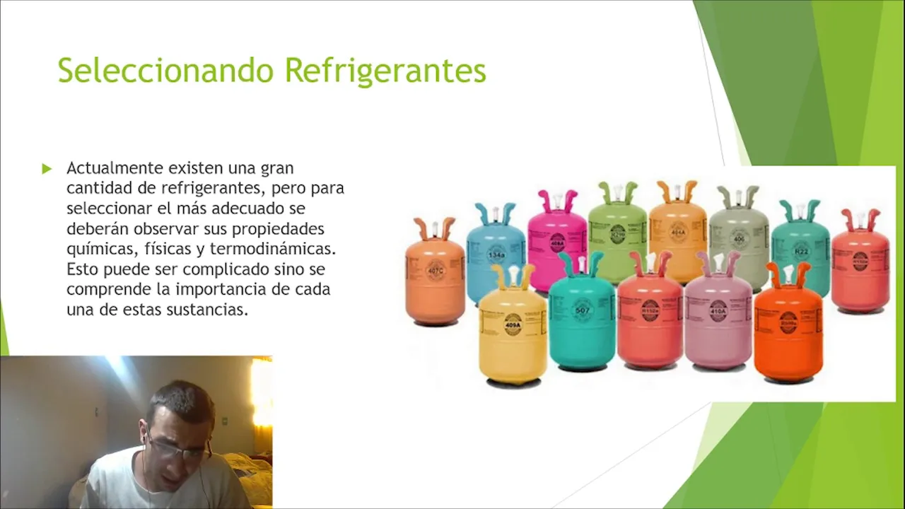
Clasificación y selección de refrigerantes
1.1K
Refrigerants are classified into pure substances and mixtures (natural, CFCs, HCFCs, HFCs). The ASHRAE Standard 34 provides a numerical classification system: series 0-100 for inorganic compounds, 100-200 for CFCs (including R134a), 200-400 for HCFCs, 400-500 for HFCs, and 700+ for inorganic compounds. The nomenclature uses uppercase letters for mixtures and numerical coding indicating fluorine, hydrogen, carbon atoms, and double bonds. Safety classification includes toxicity (Class A ≤400 ppm, Class B >400 ppm) and flammability (Class 1-3). CFCs have high ozone-depleting potential and are being phased out globally. HCFCs are also harmful to the ozone layer with production ending around 2010. HFCs contribute to global warming. CO2 is a natural refrigerant that is non-toxic and non-flammable but has reduced efficiency in warm climates. Ammonia is highly efficient and ozone-safe but toxic and flammable, requiring specialized handling.
Click to watch →
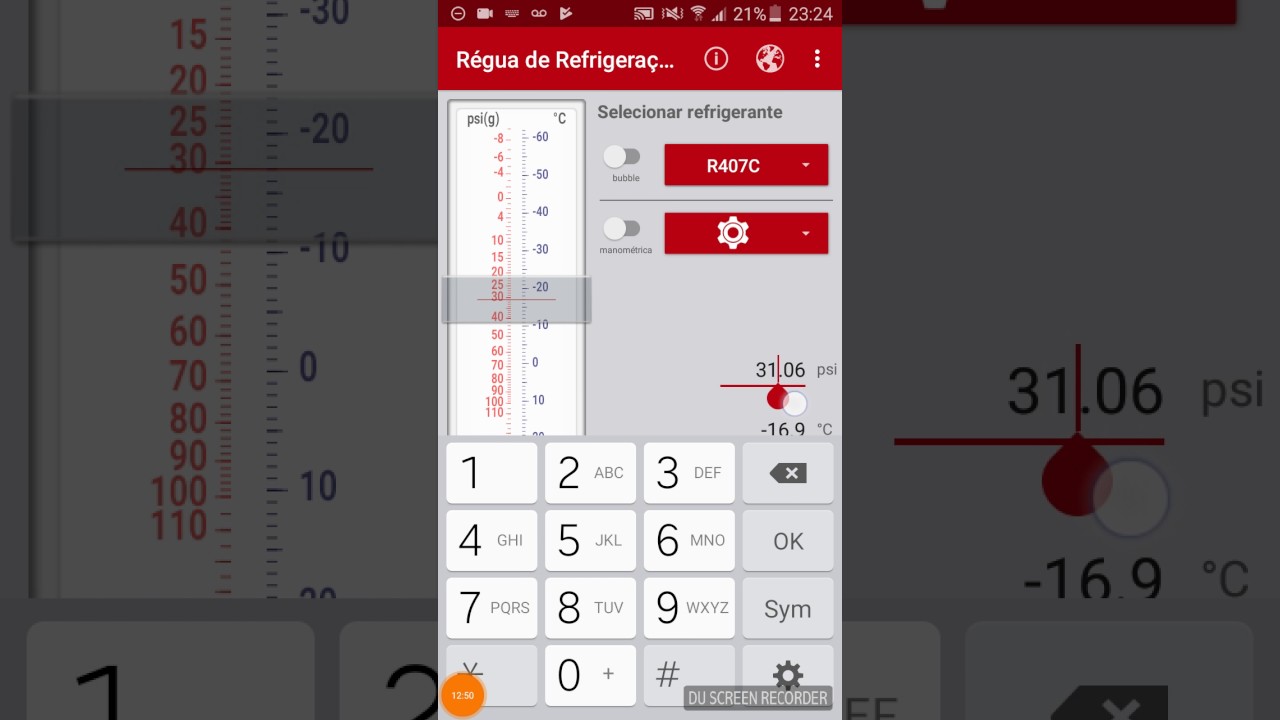
Conversão de pressão x temperatura de fluídos refrigerantes(aplicativo danfoss)
137.5K
This segment provides comprehensive information about refrigerant properties and environmental considerations. The app displays detailed specifications including GWP (Global Warming Potential), ODP (Ozone Depletion Potential), critical temperature, boiling point, chemical class (HCFC, HFC), and composition. The instructor explains that R410A has high GWP (1924) but zero ODP, while R32 has lower GWP (677) making it more environmentally friendly. The segment covers oil compatibility: R12/R22 use mineral oil, while R134a/R407C use polyolester oil, meaning direct retrofitting requires oil changes. The instructor recommends R422D and R438A as best R22 substitutes.
Click to watch →
Eco-friendly Refrigerants and its full description
2.4K
Eco-friendly refrigerants are alternatives to chlorofluorocarbons (CFCs) that have been eliminated due to ozone layer depletion and global warming potential. These alternatives are classified into four main categories: HFCs (like R134a with ODP 0.05 and GWP 1430, and R152a with ODP 0 and GWP 140), HCFCs (like R22 with ODP 0.05 and GWP 1810), natural refrigerants (like CO2 with ODP 0 and GWP 1, and water with ODP 0 and GWP 0), and hydrocarbons (like R290 propane with ODP 0 and GWP 3, and R600a isobutane with ODP 0 and GWP 3). Each category offers different trade-offs between environmental impact, energy efficiency, safety, and application suitability, with HFCs being synthetic alternatives, natural refrigerants being environmentally ideal but requiring high operating pressures, and hydrocarbons offering excellent thermodynamic properties but being flammable.
Click to watch →
Deep Dive
Exploring advanced refrigeration cycles, including multi-stage compression, cascade systems, and vapor absorption refrigeration.

VCRS (Part 2) | Complete Course on RAC | Yogesh Tyagi
10.3K
Heat exchangers are used in vapor compression refrigeration cycles to improve efficiency by pre-cooling liquid refrigerant before expansion. Cascade refrigeration systems are used when very low temperatures need to be maintained, such as cryogenic storage requiring -196°C. A single refrigeration cycle cannot achieve such temperatures efficiently. Cascade systems use multiple refrigeration cycles connected in series, with each cycle operating at different temperature ranges. The primary refrigerant circulates in the main cycle absorbing heat from the space to be cooled, while the secondary refrigerant circulates in a separate cycle absorbing heat from the primary refrigerant. Cascade systems use multi-stage compression to achieve very low temperatures, with refrigerant compressed in multiple stages with intercooling between stages, reducing work input compared to single-stage compression. The overall COP of a cascade system is calculated as: Overall COP = (Q1 + Q2) / (W1 + W2), where Q represents refrigeration effect and W represents work input for each cycle.
Click to watch →

Mechanical Engineering Thermodynamics - Lec 24, pt 3 of 4: Multistage Refrigeration Cycle
33.1K
The multi-stage vapor compression refrigeration cycle achieves performance comparable to the Cascade cycle using a single working fluid instead of two different fluids. This approach is analogous to multi-stage gas compression with intercooling. Since compressed refrigerant temperature drops below atmospheric temperature, cooling is accomplished by mixing it with refrigerant from another cycle section—a regenerative process similar to those in Rankine and Stirling cycles. The schematic includes a flash chamber that separates multiphase fluid after the condenser into saturated vapor and liquid, with vapor fraction determined by the quality after throttling.
Click to watch →

Aula 10.2 - Ciclos re refrigeração
252
Advanced refrigeration systems improve efficiency through multiple evaporation stages and multi-stage compression. A dual evaporation system uses two separate evaporation stages to achieve different temperatures in different compartments. The refrigerant first expands to an intermediate pressure corresponding to a higher temperature (e.g., 5°C), absorbs heat in the first evaporator, then expands again to a lower pressure corresponding to a lower temperature (e.g., -15°C), and absorbs additional heat in the second evaporator. This provides better temperature control but requires more complex design. A two-stage compression system uses two compressors to achieve higher efficiency. The first compressor compresses vapor from the low-temperature evaporator to an intermediate pressure, then mixes with vapor from the second compressor stage. The second compressor compresses the mixture to high pressure. A flash tank separates liquid and vapor at intermediate pressure, with vapor being recompressed and liquid going to the second expansion valve. This system improves COP by reducing compression work and increasing refrigerant available for heat absorption. Screw compressors use rotating lobes to compress refrigerant continuously, with pressure increasing linearly along the compressor's length, allowing intermediate pressure extraction for dual evaporation systems. Absorption refrigeration uses a heat source (like solar energy or waste heat) instead of mechanical work to drive the refrigeration cycle. It typically uses ammonia-water as the working pair. When heated, the solubility of ammonia in water decreases, causing ammonia to evaporate. The ammonia vapor is then condensed, expanded, and evaporated to produce cooling. The water is regenerated by absorbing the ammonia back into it. This system has no moving parts and can use low-grade heat sources. Historically used in domestic refrigerators powered by gas flames, it is now primarily used in large industrial applications and solar-powered refrigeration.
Click to watch →
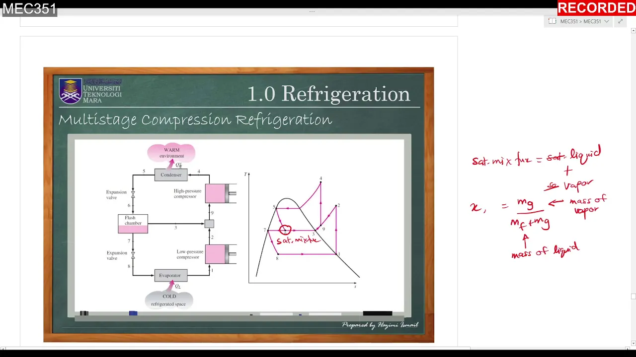
6th Lecture MEC351 Multistage Refrigeration tutorial
2.5K
The multi-stage compression refrigeration cycle differs from cascade systems by using the same refrigerant for both upper and lower stages. The system includes a high-pressure compressor at the upper stage, a low-pressure compressor at the lower stage, and a flash chamber that separates vapor and liquid refrigerant. Vapor from the flash chamber mixes with superheated refrigerant from the low-pressure compressor, then both are compressed by the high-pressure compressor. After condensation, refrigerant passes through an expansion valve to become a saturated mixture, which then separates in the flash chamber. The liquid portion goes to the lower stage expansion valve while vapor goes to the mixing chamber. A two-stage system operates between 0.8 MPa (condenser) and 0.14 MPa (evaporator) using R134a refrigerant. The refrigerant leaves the condenser as saturated liquid and is throttled to a flash chamber at 0.32 MPa, where partial evaporation occurs. Both compressors are isentropic (constant entropy).
Click to watch →
Quick Revision of Refrigeration | Complete Course on #RAC | GATE 2022 | Yogesh Tyagi
9.7K
A cascade refrigeration system uses two separate cycles operating at different pressure levels to achieve very low temperatures, consisting of two compressors, two condensers, two evaporators, and two expansion devices. The lower temperature cycle operates at lower pressures with its condenser connected to the evaporator of the higher temperature cycle. The ideal gas refrigeration cycle uses an ideal gas as working fluid with compression, heat rejection, expansion, and heat absorption processes. The COP formula is: COP = (T2 - T1) / (T3 - T2). The absorption refrigeration system uses a working pair (ammonia-water or lithium bromide-water) instead of a compressor, operating on low-grade heat energy suitable for applications with high electricity costs or limited electricity availability.
Click to watch →
Deep Dive
Practical HVAC troubleshooting and component selection, such as sizing expansion valves, compressors, and heat exchangers for specific thermal loads.
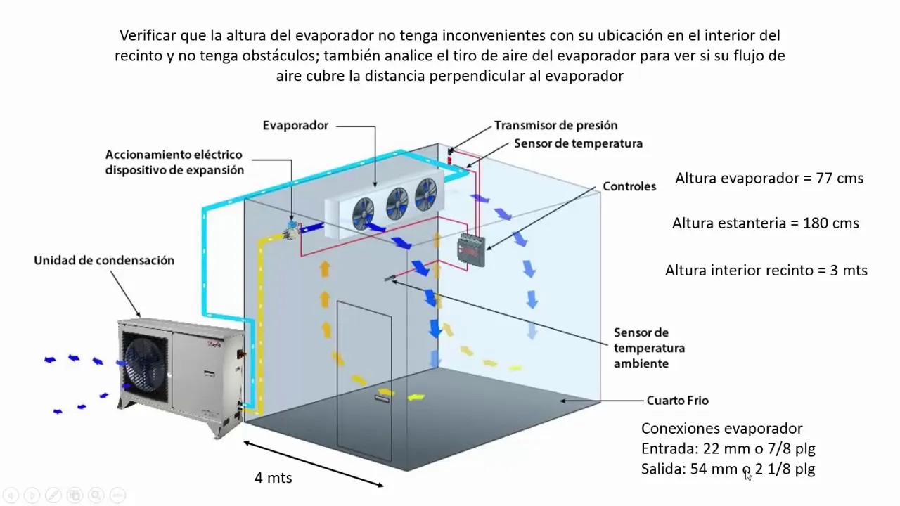
SEGUNDO VIDEO SELECCION EQUIPOS EN CUARTOS FRIOS:EVAPORADOR, UNIDAD CONDENSADORA, VALVULAS EXPANSION
20.7K
This section details the systematic approach to selecting condensers and expansion valves: (1) Condenser selection requires applying a 5% safety factor to evaporator capacity (15.7 kW becomes 16.4 kW) to account for heat absorbed in suction lines and compression heat, (2) Software-based condenser selection involves inputting capacity, temperatures, and mass flow rate, with verification that rated capacity and flow rate exceed requirements, (3) Thermostatic expansion valve selection requires inputting system parameters and verifying the valve operates within its capacity range with adequate safety margin, (4) Proper valve sizing includes selecting appropriate orifice size (TEJ 10 with orifice 11) and confirming inlet/outlet connections match system requirements.
Click to watch →

Webinar: Buenas prácticas para el mantenimiento de equipos de refrigeración
3.7K
Correct compressor selection requires considering: (1) Refrigerant type - each compressor is approved for specific refrigerants with particular pressure levels, (2) Voltage and frequency - must match the electrical system, (3) Application temperature range - defined by evaporation temperature: High Pressure Return (HP) for water coolers (0°C to +15°C), Medium/Low Pressure Return (MLVP) for beverage coolers (above 15°C), and Low Pressure Return (LVP) for freezers (-35°C). Expansion devices (capillary tubes and TXV valves) reduce pressure opposite to the compressor's function. Capillary tubes allow pressure equalization between compressor sides when stopped, while TXV valves restrict flow and prevent equalization. Low starting torque compressors cannot work with TXV valves because they cannot overcome the pressure difference during startup.
Click to watch →

HVAC Thermal Expansion Valves
201.2K
Thermal expansion valves (TXVs) are critical HVAC components that regulate refrigerant flow to the evaporator based on system demand, with valve size directly corresponding to system capacity (e.g., 4-ton, 11-ton, 30-ton systems); these valves feature a power head containing refrigerant that responds to suction line temperature via a bulb, and an externally equalized design with a copper tube connecting to the suction line, while proper installation requires brazing the valve body and adjusting the pin mechanism to control refrigerant flow according to superheat requirements.
Click to watch →

Seleção de Componentes Câmara Frigorifica!! @VideoAula1 @refrigeração
1.9K
This section provides a comprehensive methodology for selecting the three major refrigeration components. For condensers, the presenter demonstrates using external temperature (35°C) and evaporation temperature (-15°C) to find matching capacity in manufacturer tables, emphasizing the importance of operating range - condensers should ideally operate in the middle of their specified range to avoid superheat or subcooling issues. For expansion devices, he explains converting thermal load from BTU/h to kW by dividing by 860, then selecting the closest matching capacity. The presenter discusses the relationship between selected device capacity and actual system load, explaining how to determine whether to open or close the valve during installation. He also covers auxiliary components including oil separator (selecting based on thermal load, refrigerant type, and evaporation temperature 20°C below actual), liquid tank (calculating mass flow rate by dividing thermal load by refrigerant's volumetric cooling capacity, then converting to volume using refrigerant density), filter drier (converting thermal load to tons of refrigeration and selecting minimum size), liquid sight glass (matching connection size to liquid line), and solenoid valve (converting thermal load to TR and selecting closest matching capacity).
Click to watch →

251206-1 Kalkulasi cooling capasity & seleksi CDU serta bandingkan comp full ~ semi hermetic
170
This segment covers the detailed process of sizing expansion valves and condensers for refrigeration systems. The expansion valve calculation involves taking the cooling capacity requirement and subtracting a delta T value (typically 5°C) to determine appropriate capacity. The speaker demonstrates this with examples: 10,300W minus 5°C equals 2.9 ton capacity, and 10,670W minus 5°C equals 3 ton capacity. For condenser sizing, the speaker uses the Bitzer application, selecting appropriate compressor models (2 chest 3Y or 2 chest 4Y), setting inlet temperatures (e.g., 7.5°C), and reading condenser capacity outputs (e.g., 20.7 KW). The segment emphasizes that for medium temperature applications, the 2 chest 4Y model is preferred over 2 chest 3Y.
Click to watch →
Core parts
Cycle flow
Pressure state
Heat transfer
Refrigerant role
Low temp state
Cycle repeat
Core parts
0:04- 1
Identifies compressor, condenser, and expansion valve.
- 2
Lists evaporator as the fourth main component.
Thermally-Driven and Solid-State Cooling Alternatives
While the Vapor Compression Refrigeration Cycle (VCRC) is the dominant cooling technology, it faces criticism for its high electricity consumption and reliance on environmentally harmful chemical refrigerants (like HFCs). To broaden their perspective, students should explore alternative thermodynamic systems that bypass mechanical compression. The Vapor Absorption Refrigeration Cycle replaces the electric compressor with a heat-driven process, utilizing waste heat or solar energy to drive cooling. Additionally, emerging technologies like Thermoelectric and Magnetocaloric (Solid-State) Refrigeration eliminate chemical refrigerants and moving parts entirely, using electrical currents or magnetic fields to transfer heat. Exploring these alternatives highlights that refrigeration can be achieved without the high mechanical work and ecological drawbacks inherent to the standard compression cycle.
Basic principles of thermodynamics, specifically the concept of heat transfer and the Second Law of Thermodynamics.
The concept of phase change (latent heat), including how substances absorb heat during evaporation and release it during condensation.
The relationship between pressure and temperature, particularly how changing the pressure of a fluid alters its boiling point.
Fundamental heat transfer mechanisms, such as conduction and convection, and how fluids absorb and reject thermal energy.
Analyzing the vapor compression cycle on a Pressure-Enthalpy (p-h) diagram to calculate the Coefficient of Performance (COP).
Understanding the properties and environmental impacts of different refrigerants (e.g., HCFCs, HFCs, and natural refrigerants like CO2 and Ammonia).
Exploring advanced refrigeration cycles, including multi-stage compression, cascade systems, and vapor absorption refrigeration.
Practical HVAC troubleshooting and component selection, such as sizing expansion valves, compressors, and heat exchangers for specific thermal loads.
1.8M views42.2Klikes5:57@girishshindeOriginal Release: 2016-04-05
compressor condenser expansion device or evaporator um foreign foreign foreign [Applause] foreign foreign foreign foreign liquid refrigerant refrigerant low pressure low temperature liquid reference surrounding temperatures cycle foreign [Laughter] [Laughter]
Up Next

28:41
1902 Air Conditioning Invention: How AC Transformed American Design and Demographics
@99percentinvisiblepodcast
226 views•2023-01-06

30:32
Ultrasonic Transducers: Resonant Frequency Measurement and Horn Design
@imajeenyus42
229.9K views•2017-02-22

54:16
Polymer Environmental Degradation: Mechanisms & Stabilization
@iit
1.8K views•2012-07-10

33:39
How a Student's Question Saved a NYC Skyscraper from Collapse
@veritasium
22.8M views•2025-04-26
Related Study Plans & Knowledge Roadmaps
Structured learning paths in Engineering
engineering
Building Acoustic Levitators: Physics & Arduino
01The Physics of Sound and Standing Waves
02Piezoelectric Transducers and H-Bridge Drivers
03Arduino Programming: Generating 40 kHz Signals
+ 2 more learning modules
14h5 modules
Explore Roadmap
engineering
Building Peltier Cloud Chambers: Particle Tracks
01Cosmic Rays & Cloud Chamber Physics
02Thermoelectric Cooling (TEC) Fundamentals
03Custom Liquid-Cooling Loop Design
+ 2 more learning modules
18h5 modules
Explore Roadmap
engineering
Yagi-Uda Antennas: Modeling, Build & VNA Test
01Introduction to RF and Antenna Fundamentals
02Yagi-Uda Antenna Design Principles
03Antenna Modeling and Simulation in 4NEC2
+ 2 more learning modules
18h5 modules
Explore Roadmap
engineering
ECG Monitor Design: Op-Amps, Filters & Noise
01Electronics & Breadboard Basics
02Op-Amps and Instrumentation Amplifiers
03Bioelectricity and ECG Fundamentals
+ 2 more learning modules
18h5 modules
Explore Roadmap