









![Type of Gearbox in Automobile Vehicles [Explained in Detail] 2021](https://i.ytimg.com/vi_webp/1xLpuCooSf8/maxresdefault.webp)



![[ VẬT LÍ 12 - ÔN TẬP KIỂM TRA GIỮA KÌ 2] Chữa đề GK02 - số 05 | IPCLASS](https://i.ytimg.com/vi/7xSStfAW47s/maxresdefault.jpg)



![[Webinar] Magnetic-Geared Permanent Magnet Synchronous Motor for E-Mobility](https://i.ytimg.com/vi/8Ycf3XjXvvw/maxresdefault.jpg)



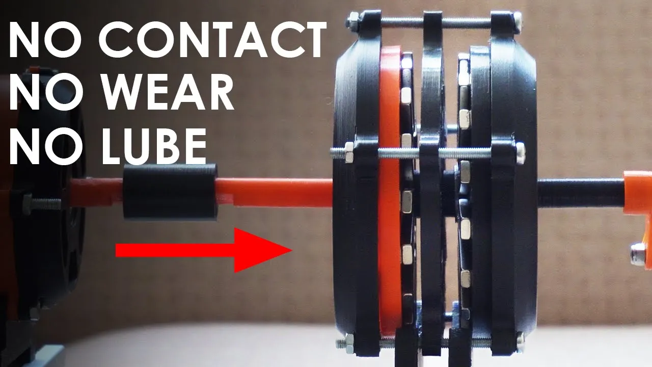










This video demonstrates how to measure the efficiency of magnetic gearboxes by using an electromagnetic brake system that applies variable frictional loads to the output shaft while simultaneously measuring input and output speeds and torques; the experiment reveals that while properly aligned mechanical gears achieve over 95% efficiency, a single-stage magnetic gearbox with a 4:1 reduction ratio only achieves approximately 55% efficiency, demonstrating that magnetic gears suffer significantly higher power losses due to magnetic hysteresis and eddy current effects compared to traditional mechanical gears.
Measuring Magnetic Gearbox Efficiency: Test Rig & Electromagnetic Brake Build
Added:Principles of Electromagnetism: Understanding magnetic flux, magnetic coupling, and how permanent magnets interact to transfer torque without physical contact.
Mechanical Power and Efficiency: Familiarity with the mathematical relationship between torque, rotational speed (RPM), input/output power, and the definition of mechanical efficiency.
Conventional Gearbox Mechanics: Basic understanding of how traditional mechanical gears operate, including gear ratios and standard sources of friction and wear.
Electromagnetic Braking and Eddy Currents: Knowledge of how relative motion between a magnet and a conductor induces currents (Lenz's Law) to create a controllable braking load.
Loss Analysis in Magnetic Systems: Investigating the specific sources of the 45% energy loss, such as eddy current losses in modulating steel poles and hysteresis losses in magnetic materials.
Optimization of Magnetic Gear Topologies: Exploring advanced magnetic arrangements, such as Halbach arrays, to minimize flux leakage and improve torque transfer efficiency.
Thermal Management in Electromagnetic Devices: Studying how heat generated by magnetic and electric losses affects magnetic coercivity, remanence, and system longevity.
Industrial Applications and Trade-offs: Assessing real-world scenarios (e.g., wind energy, subsea propulsion, or aerospace) where the benefits of contact-free operation and overload protection outweigh the efficiency deficit.
48K views1.1Klikes16:39Original Release: 2023-06-26
this gearbox runs purely using magnetic forces you might be wondering where the gearbox is right now in fact if you look a little bit closer you can see the screw heads in the middle as if they are being pushed by invisible arms anyway here it is super quiet there's no wear and tear and so no lubrication seriously impressive but here's the thing I honestly don't know how efficient they are I believe they are inefficient and mechanical gears but I have nothing to prove it yet because trust me it's not easy to find efficiency for this we gotta figure out the mechanical Power which means measuring the shaft speed and Torque simultaneously which is the tricky part because let's say you want to find that mechanical Power on the output I can measure the speed using a magnetic sensor inside the bearing block but when I try to measure the torque as you can see this time the motor starts I can't measure the speed it's kinda ironic but we can actually use these magnetic gear works as a solution even though the torque arm tries to stop the output shaft the magnetic connection between the modulator and the sun gear allows the rotors to slip over each other just as the output shaft is about to stop so the shaft can keep moving and that way we can measure the torque without stopping the system it's a decent solution but the issue here is since these are permanent magnets the slipping point of the rotors is always the same so no matter how much load I applied on the shaft the applied load stays the same I can't change the load on the shaft so how about using tiny electromagnets instead of every single permanent magnet here to change the load I mean that would be nice but there are so many magnets here fortunately I have another solution so this method relies mainly on the friction between the electromagnet and the brake disc rather than the interaction of the magnets in the previous magnetic gear and this has two significant advantages that solve the previous issues first of all the connection between the magnet and the disc is magnetic so the output shaft can keep going secondly we can now change the load on the shaft by changing the frictional force between them through the electromagnet okay before doing a quick test this steel core was machined by PCB way I just did the design they did the rest there is also this brake disc just perfect they were machined in PCB with CNC Services they offer all sorts of materials from plexiglass to Titanium and these two parts are made of 1018 Steel this will also provide sheet metal fabrication 3D printing and other services you see here and they are really good at that they could be a great solution like this one here so big thanks to PCV for sponsoring this video okay let's see if this works start tomorrow okay the sound is good oh wait so basically it works but there's a slight issue check this out the reading when the magnet is off is around 60 grams I'm giving power to the magnet as you can see almost 200 grams now I'm cutting off the current and it's at just 115 grams so why didn't it throw back to 60 grams again and even though I cut current the brake disc is still not separated from the magnet yet the reason for this is the residual magnetization remaining in the core and the reason for the residual magnetization in the core is actually similar to the situation in this green film so this green film is a magnetic field viewer and basically there are a bunch of tiny nickel particles in it that can freely rotate and when we turn on the magnet these nickel particles try to align themselves with the magnetic field lines in the area that currently appears bright the field lines are kind of straight and the nickel particles also become straight which reflects the light and makes it look shiny but once one sides don't reflect the light and so they stay dark so we can literally see what's going on here it's really great now back to the problem similarly this metal core also contains very small magnetic domains and when we give current to the coil and create an external magnetic field in a certain direction these domains align themselves like the external magnetic field and that's how this metal core becomes magnetized the thing is when I remove the magnet from the film The nickel particles can't fully return to their initial form the center is still a bit dark just like that the Aligned domains within this steel color when the current is cut off cannot follow this magnetization curve exactly and return to their initial form drops to such a retentivity value and as a result that remains a residual magnetization within this material and this as you can see keeps the disk from separating to give an idea of this residual magnetization I first gave power to the magnet then cut the power off and tried to pull to this straight and repeated this for different current values and yes I use the pulley system here because the residual magnetization is not a little thing at all and at the maximum current we can apply to this coil wire There is almost 40 kilo of residual Force left in the magnet I want to point out again that this is the force required to pull the disc after the magnet is turned off and this is quite High so how do we pull this back the main reason for this is the resistance of the domain walls which we initially forced to move by applying current to the coil to move again after the current is removed which it is quite normal for them not to move on their own when the current is removed because the force acting on them is removed so in this case if we apply current in the opposite direction domain walls will start to move in the opposite direction and demagnetizing the core and the only thing to do for this just reversing the polarity as you can see it really is that simple I can separate the disk from the magnet in this way but I can only pull the disk run residual magnetization drops to zero and to get it to zero I have to apply exactly this much opposite field How to know that precisely mind slider for this was to make a few custom springs on the lathe I was going to put them on a fixed Hub so that without the need to know the exact opposite field required when the residual magnetization drops zero the Springs would sense it and directly pull the disc back but you hear that sound coming from the late right I think I pushed this mini too much and burned out something in the control board I gave some 3D printed flat Springs a try though it didn't work too well either then I thought why not use magnetic forces as a spring I'll Place permanent magnets on the disc and the Hub with opposite poles facing each other in this way just like a mechanical spring continuesly trying to pull the disc back here the interaction between the opposite poles will continuously try to pull the disc back and this could definitely work so the electromagnetic brake is ready it turned out a bit heavy though considering it's made of steel I made some changes to the gearbox the previous one was falling apart the last move is to include it in the test rig as the output shaft so let's see if our invisible Springs work okay the magnet has attracted the disc I'll cut the power now it didn't come back as expected again now I will apply opposite field and the magnets will attract the disk just as residual field drops to zero oh okay residual magnetization dropped to Zero by reverse field that this came back but since I didn't cut the power right at this point it attracted disk Again by opposite magnetization I need to quickly turn off the power supply right at this point yeah so maybe it's not exactly a mechanical spring but there's basically an invisible spring here right now okay let's give it a little try all right let's slow down dude no way seriously it was clear though okay first of all these are not even warm consider it cold but there has definitely been a lot of friction here the core is in better condition compared to the disc with not as much wear however the disc will definitely thin out over time by the way I got all the data while the system was running now getting back the main point of the video as you can see we are now able to measure both speed and 4 simultaneously this allows us to calculate the mechanical Power at the output shaft however when it comes to gearbox efficiency we also need to find the mechanical Power at the input shaft and make a comparison and the good news is there is no need one more bridge for the input power I'm sure many of you have seen this before when the rotor starts to rotate the stator and therefore the motor body also starts rotating the opposite direction with an equal but oppository and if the sport is smaller freely we can measure the torque on the other I am in the torque on input shaft using a torque arm attached to motor body okay don't mind how crowded looks I've just got the model freely mounted and the brake is in place as before and in between we have this herringbone gearbox whose performance I'm curious about so let's start the motor and here comes first data so first of all I'm measuring the input and output speed throughout the process there's a difference all about 12 times between them that matches the gear ratio and I'm getting the forces measured from these load cells multiply them by a token distances to calculate the breaking tokens output and the reaction talk at the input currently the braking force and torque are zero because the brake disc is not contacted with the magnet yet but since the motor is spinning there's a reaction force although it's not affected the reaction talk ideally this should be zero because when calculating efficiency it's crucial to compare the applied load with the corresponding reaction in the current script with no load applied that should also not be any reaction force so rather than zeroing this force of about 2.5 grams I'll deduct it from the total Force for now so okay let's just give some load to the shaft as you can understand from the sound the output shaft is now under a certain load the braking torque is around 0.4 Newton meter and in response to this load the model creates a reaction torque of 0.04 Newton meter now let's move on to the mechanical Power on each shaft using this and here are the mechanical Power ratings in Watts according to the calculation there's a power loss of about 2 Watts between the input and output shafts as you can see around 10 watts are entering to the gearbox but only around 8 watts are coming out this loss inevitably due to some reasons such as tooth friction or bearing losses in this case if we compare the input and output Powers this gearbox has an average efficiency of around 82 percent so it's not too bad for now but the performance of these gears actually varies depending on the speed and load as well this was the performance on robot 1800 RPM and 0.5 new to Middle load so I tested it again by keeping the load constant and varying the model speed and I found that the efficiency increased with the increasing speed up to a certain point and again under a load of 0.5 Newton meter this gearbox performed the best around 4200 RPM with an efficiency of around 84 percent so consisting of these two stage hanging one gears with 12 gear ratio notification poorly aligned and supported and most importantly the 3D printing gearbox cause the power loss of about 15 when converting a power from any speed and torque to another speed and torque how about magnetic gear racks okay let's put this onto the output shaft this magnetic gearbox is a single stage design with four reduction ratio so the electromagnet is not connected now because this magnetic gear has an incredibly low torque capacity so even with very little touch I can't stop the shaft and as you can see the rotors just slipping on each other even though it's a very small I applied a load of about 0.03 Newton Middle on the output shaft which is very close to the slipping torque of the others in response there is a reaction torque of 0.01 Newton meter created on the input shafts and as you can see there's roughly a four speed ratio between the input and output so in this case this magnetic gearbox has an average efficiency of only 55 percent 30 lower than mechanical gears which is a huge loss indeed I only get half the power I give I went on increasing the speed as before went up to 5000 RPM I would like to say that the efficiency increased but it dropped to around 20 and surprisingly the magnetic connection did not break but that tiny magnet I was using to measure the speed came of its place and I didn't go longer because the situation is already obvious in the end the efficiency decreased significantly as the speed increased likely due to Magnetic losses Unfortunately they don't appear to be very efficient but since the load is very low I cannot Place much confidence in the test results after this part but either way it's lower than the mechanical gears the ironic part is properly aligned Metal Gears although they have an efficiency over 95 percent so I don't know if I expect it to be 120 or something thanks for watching if you like it make sure subscribe
Up Next
24:43
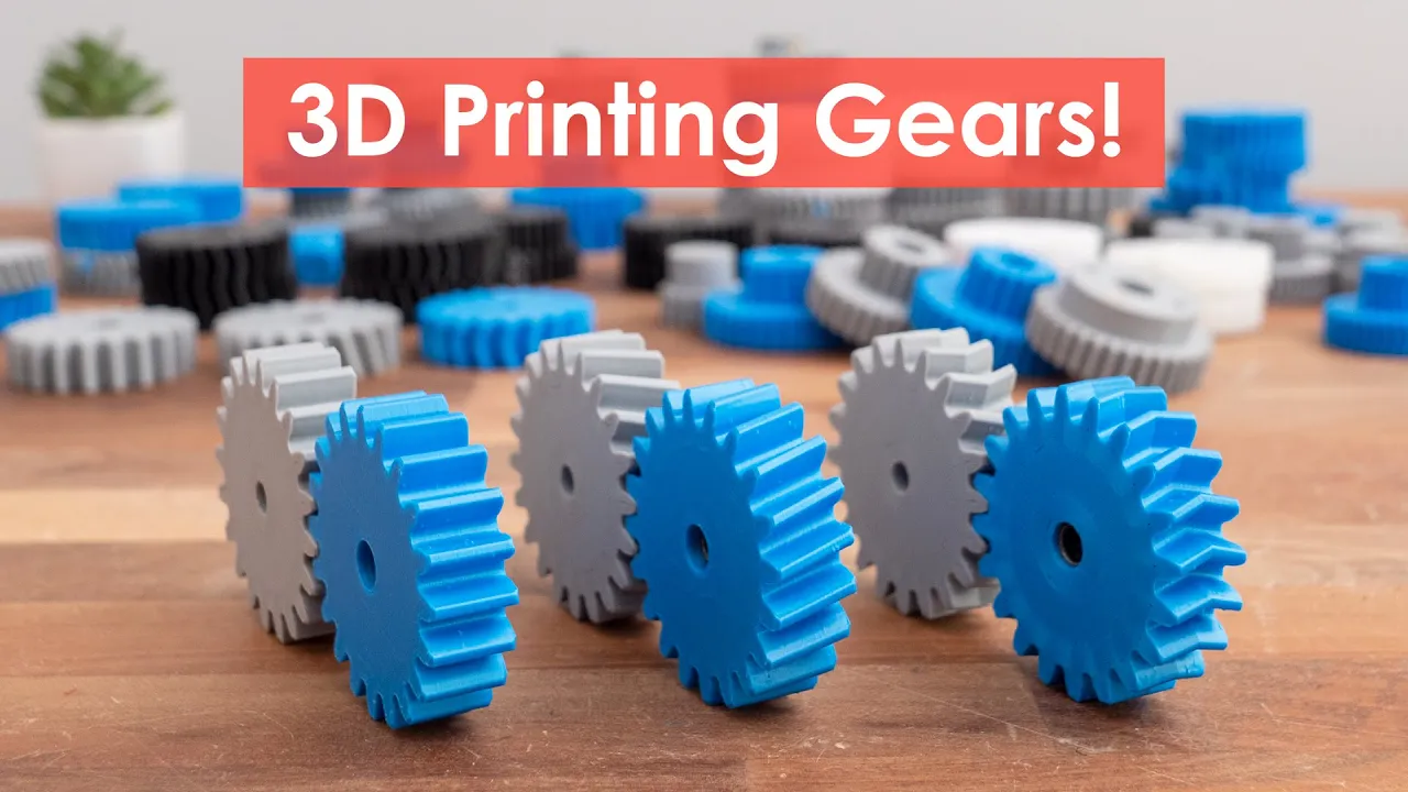
3D Printed Gears: Strength, Efficiency & Materials Guide
@HowToMechatronics
176.8K views•2024-06-09

30:32
Ultrasonic Transducers: Resonant Frequency Measurement and Horn Design
@imajeenyus42
229.9K views•2017-02-22

54:16
Polymer Environmental Degradation: Mechanisms & Stabilization
@iit
1.8K views•2012-07-10

33:39
How a Student's Question Saved a NYC Skyscraper from Collapse
@veritasium
22.8M views•2025-04-26
Related Study Plans & Knowledge Roadmaps
Structured learning paths in Engineering
engineering
Building Acoustic Levitators: Physics & Arduino
01The Physics of Sound and Standing Waves
02Piezoelectric Transducers and H-Bridge Drivers
03Arduino Programming: Generating 40 kHz Signals
+ 2 more learning modules
14h5 modules
Explore Roadmap
engineering
Building Peltier Cloud Chambers: Particle Tracks
01Cosmic Rays & Cloud Chamber Physics
02Thermoelectric Cooling (TEC) Fundamentals
03Custom Liquid-Cooling Loop Design
+ 2 more learning modules
18h5 modules
Explore Roadmap
engineering
Yagi-Uda Antennas: Modeling, Build & VNA Test
01Introduction to RF and Antenna Fundamentals
02Yagi-Uda Antenna Design Principles
03Antenna Modeling and Simulation in 4NEC2
+ 2 more learning modules
18h5 modules
Explore Roadmap
engineering
ECG Monitor Design: Op-Amps, Filters & Noise
01Electronics & Breadboard Basics
02Op-Amps and Instrumentation Amplifiers
03Bioelectricity and ECG Fundamentals
+ 2 more learning modules
18h5 modules
Explore Roadmap