L4 load balancing operates at the transport layer, forwarding packets based on IP and port numbers using simple policies like round robin or least connections, making it fast and secure but unable to inspect request content; it's ideal for performance-critical applications like video streaming. L7 load balancing operates at the application layer, inspecting headers, URLs, cookies, and request bodies to route requests to specific servers based on content, making it essential for microservices and APIs but requiring more processing overhead.
L4 vs L7 Load Balancing: OSI Model Explained
Added:Deep Dive
Basic understanding of the OSI (Open Systems Interconnection) model, specifically the functional differences between the Transport Layer (Layer 4) and the Application Layer (Layer 7).

Computer Network Unit 5 ONE SHOT | Transport Layer | AL602 RGPV Exam | Notes 👍 | By Sant Yadav 🚀
1.4K
The Transport Layer (Layer 4) sits between Network and Application layers, responsible for end-to-end communication. Core responsibilities include multiplexing/demultiplexing via port numbers, reliable delivery, error control, flow control, and connection management. Two main protocols exist: UDP (connectionless, fast, unreliable - no setup, no acknowledgments, ideal for gaming/streaming) and TCP (connection-oriented, reliable, stream-based - uses three-way handshake, sequence numbers, retransmission, sliding window protocol). The Application Layer provides user interfaces for services like HTTP/HTTPS (web browsing), FTP (file transfer), SSH (secure remote access), email protocols (SMTP, IMAP, POP3), and DNS (name resolution). Network management monitors devices like routers, switches, and firewalls to ensure proper operation.
Click to watch →

OSI Model OSI 7 Layer ภาษาไทย
7.3K
The OSI (Open System Interconnection) Model is a 7-layer framework developed by ISO to standardize network communication across different hardware and software systems, solving the problem of proprietary systems where devices from different manufacturers (like IBM and Apple) could not communicate with each other. The 7 layers, from top to bottom, are: Application Layer (Layer 7) handles user interface and application programs; Presentation Layer (Layer 6) manages data encoding/decoding and formatting; Session Layer (Layer 5) establishes and manages communication sessions; Transport Layer (Layer 4) provides reliable data transmission via TCP or UDP; Network Layer (Layer 3) handles logical addressing and routing using IP addresses; Data Link Layer (Layer 2) manages physical addressing and switching using MAC addresses; Physical Layer (Layer 1) deals with hardware and transmission media.
Click to watch →

OSI Model | OSI Model Explained | CCNA/CCNP | OSI Animation | OSI Model in easiest Way | OSI 7 Layer
9.7K
The upper four layers of the OSI model handle network application functionality and data delivery. The Application Layer (Layer 7) provides the interface for network applications like browsers and email clients, using protocols such as HTTP, FTP, SMTP, and Telnet. The Presentation Layer (Layer 6) converts data to binary format, compresses it for efficient transmission, and encrypts it for security using protocols like SSL. The Session Layer (Layer 5) establishes and maintains connections between applications, handles authentication and authorization, and manages session lifecycle. The Transport Layer (Layer 4) manages service-to-service delivery using port numbers (0-65,535) and protocols. TCP provides reliability with error checking and retransmission, while UDP provides efficiency. Each network application uses a specific well-known port, and random source ports allow multiple simultaneous connections to the same server by isolating data streams.
Click to watch →
Episode 1 | Introduction to Networking: Models, Protocols, and the OSI Framework | BCIS 3347
171
Layer 4 (Transport) manages end-to-end reliability with TCP (connection-oriented, reliable) and UDP (connectionless, fast). Layer 5-6 (Session/Presentation) handle dialogue management and data formatting/encryption. Layer 7 (Application) provides user-facing protocols like HTTP, SMTP, FTP, and DNS. This layer makes networks useful for specific tasks by defining application-specific commands and formats.
Click to watch →

מודל שבע השכבות OSI ואסופת פרוטוקולי TCP/IP
147.4K
The Transport Layer (Layer 4) is responsible for segmenting data and managing reliable delivery services. When data arrives from the Application Layer, it is typically divided into smaller chunks called segments. This layer includes two main services: reliable delivery (where all packets must arrive and the sender receives confirmation) and fast, real-time delivery (used for applications like VoIP where speed is more important than perfect accuracy). The Transport Layer ensures that data reaches its destination correctly and in the proper order.
Click to watch →
Deep Dive
Fundamental concepts of TCP/IP networking, including how IP addresses, ports, and protocols (TCP/UDP) facilitate communication.
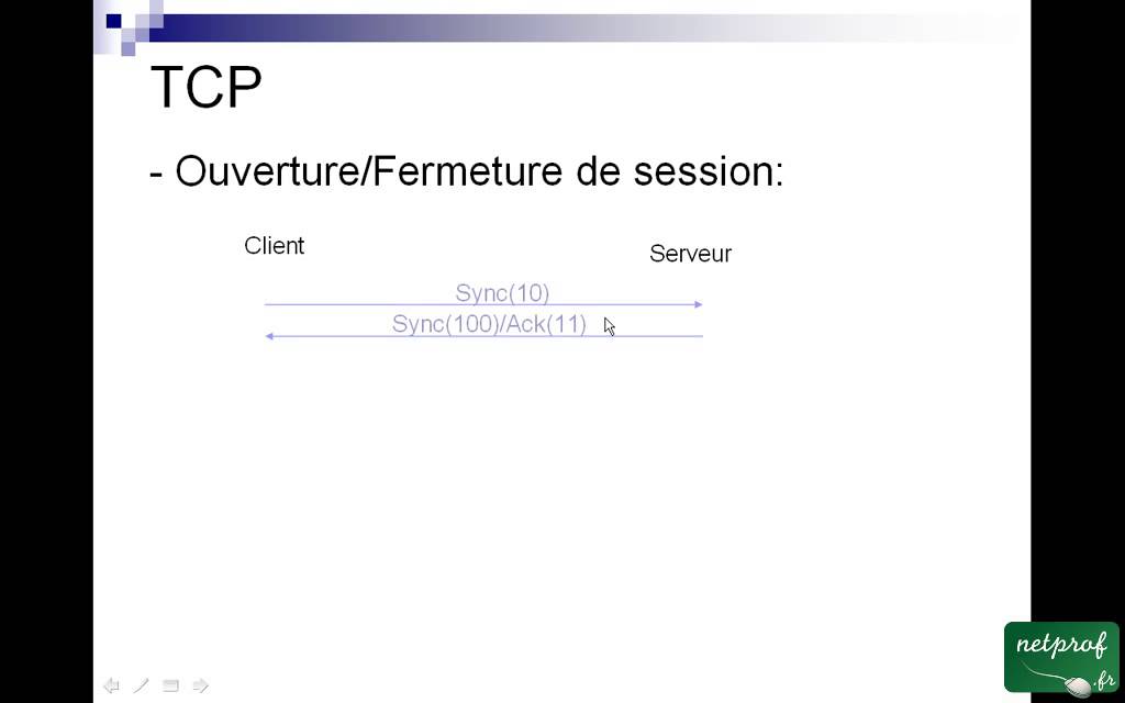
2 TCP/IP (le IP)
171.9K
TCP/IP is an ensemble of protocols including TCP, IP, UDP, ICMP, and others. The four-layer architecture consists of: Application Layer (HTTP, FTP, DNS), Transport Layer (TCP, UDP), Internet Layer (IP), and Network Access Layer (Ethernet, WiFi, DSL). Communication follows client-server architecture where clients initiate connections and servers provide data. Port numbers (0-65535) identify applications: destination port identifies server application (e.g., port 80 for web), source port identifies client process. Standard ports include 80 (HTTP), 25 (SMTP), 21 (FTP). TCP provides reliable transport with acknowledgments and retransmission, using three-way handshake (SYN, SYN-ACK, ACK) for connection establishment. UDP is connectionless and unreliable, used for DNS and streaming. IP addresses consist of 4 octets (0-255 each), written in decimal notation. They have hierarchical structure: network identifier and machine identifier. Special addresses: .0 identifies the network, .255 is broadcast address. Subnet masks indicate network vs machine portions. IP classes: Class A (1-126, /8 mask, 16 million hosts), Class B (128-191, /16 mask, 65,534 hosts), Class C (192-223, /24 mask, 254 hosts). Two machines share a network if they have the same network identifier with the same subnet mask.
Click to watch →

Lecture -3 TCP/IP - Part-1
323.9K
The three fundamental TCP/IP protocols serve distinct purposes: (1) IP (Internet Protocol) at the network layer provides connectionless, unreliable packet delivery with routing and fragmentation/reassembly capabilities; (2) TCP (Transmission Control Protocol) at the transport layer provides reliable, connection-oriented service ensuring data arrives correctly and in order through error checking and retransmission; (3) UDP (User Datagram Protocol) provides fast, connectionless service without reliability guarantees, suitable for small messages like DNS queries. Together, these protocols form the foundation of internet communication, with TCP providing reliable streams and UDP offering lightweight, fast delivery for specific applications.
Click to watch →

O que são portas TCP e UDP?
46.8K
TCP/IP networking uses IP addresses and port numbers to identify devices and services. The IP address consists of a network portion (like a street name) and a host portion (like a house number), with the subnet mask acting as a separator. Port numbers function as additional identifiers, similar to apartment numbers in a building, specifying which service on a device should receive data. When a client sends a request to a server, the port number indicates what type of service is being requested, such as web browsing or email.
Click to watch →

Controla tu Casa desde Internet - Primera Mirada Modulo Ethernet Shield W5100 - Parte1
75.2K
TCP/IP (Transmission Control Protocol/Internet Protocol) is the fundamental communication protocol for LAN and internet. The stack includes TCP (reliable transmission), IP (addressing and routing), UDP (faster but less reliable), and ICMP (diagnostics). Each network device requires a unique IP address divided into classes: Class A (10.x.x.x), Class B (172.16-31.x.x), and Class C (192.168.1-254.x.x). For home networks, Class C addresses are standard, with the first three numbers defining the subnet and the last number identifying the device. Addresses 0 and 255 are reserved for network and broadcast purposes.
Click to watch →

Introduction to IP - N10-008 CompTIA Network+ : 1.5
132.8K
Network communication uses a layered protocol stack where IP (Internet Protocol) functions as the 'moving truck' transporting data across electronic roads (Ethernet, cable, DSL). Inside IP, TCP or UDP protocols carry application data. TCP is connection-oriented and reliable, requiring setup, acknowledgements, and sequence numbers for reassembly. UDP is connectionless and unreliable, sending data without acknowledgements. IP addresses function as logical network locations, while port numbers designate specific services on a device. Well-known ports (0-1023) are permanent and associated with services like HTTP (port 80) and HTTPS (port 443). Ephemeral ports (1024-65535) are temporary and randomly assigned by clients. The combination of IP address and port number forms a 'socket' that uniquely identifies a communication endpoint. Multiplexing enables multiple applications to communicate simultaneously over the same network connection to a single device, with the server differentiating data types by examining port numbers. TCP and UDP port numbers are protocol-specific.
Click to watch →
Deep Dive
Familiarity with web protocols, particularly HTTP and HTTPS, and how client-server communication works.

Фронтенд, Бэкенд и Фулл Стек
80.3K
HTTP (HyperText Transfer Protocol) is the most common protocol for communication between clients and servers. HTTPS is the secure version of HTTP that uses digital certificates and TLS (Transport Layer Security) protocol to encrypt data transmitted between clients and servers. HTTPS supports both static data transfer (images, CSS, JavaScript files) and dynamic data exchange.
Click to watch →

Difference between 1 Tier, 2 Tier, 3 Tier and Multi-tier Architecture in Web Applications in Hindi
44.8K
Communication between web clients and servers occurs through specific protocols. HTTP (HyperText Transfer Protocol) is the standard protocol for transmitting data over the web. HTTPS (HyperText Transfer Protocol Secure) is the secure version that encrypts data transmission. When a user accesses a website like www.abc.com, their request travels to the web server using these protocols, and the server responds by sending the requested webpage content back to the client's browser.
Click to watch →

43. Клієнт-серверна архітектура. HTTP, HTTPS
41.6K
Client-server architecture is a fundamental web development model where clients (like browsers) send requests to servers (powerful machines that process data and store information), with HTTP (HyperText Transfer Protocol) enabling data transmission and HTTPS adding encryption for secure communication. This architecture can be implemented in two-level (client-server), three-level (client-server-database), or multi-level configurations, with thick clients performing most processing locally while thin clients rely on servers for computation.
Click to watch →
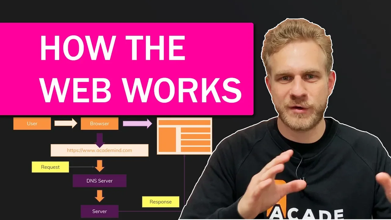
How The Web Works - The Big Picture
639.4K
HTTP (HyperText Transfer Protocol) is the standard protocol governing how data is transferred between browsers and servers. HTTPS is the secure version of HTTP that encrypts all data exchanged between client and server. Modern websites use HTTPS to ensure end-to-end encryption, meaning even if someone intercepts your internet traffic, they will only see unreadable encrypted content. Both protocols define standardized formats for requests and responses, ensuring compatibility across different browsers and servers.
Click to watch →

2º AULÃO DE INFORMÁTICA PARA O BANCO DO BRASIL
92.6K
HTTP (HyperText Transfer Protocol) is the standard protocol used for transferring web pages from servers to browsers. When a user visits a website, their browser communicates with the server using HTTP to request and receive the HTML pages that make up the website. HTTP is a protocol of communication that defines how data is transmitted between the client (browser) and the server. However, HTTP is not secure because data transmitted over it can be intercepted and read by attackers. HTTPS (HyperText Transfer Protocol Secure) is the secure version of HTTP that uses encryption to protect data transmitted between the user's browser and the website. The 'S' in HTTPS stands for Secure and indicates that the communication is encrypted.
Click to watch →
Deep Dive
The general purpose of a load balancer in system architecture, such as achieving high availability and distributing traffic.

How to Set Up Load Balancing for High Availability @Cephstorage
9.5K
A load balancer sits in front of applications to distribute incoming requests across multiple backend servers. It serves two primary purposes: distributing traffic to prevent server overload (common for high-traffic websites) and providing high availability by rerouting traffic when servers fail. Additional capabilities include HTTPS termination (centralizing SSL/TLS management), HTTP header-based routing, URL path routing, and cookie-based sticky sessions that maintain user sessions on specific backend servers.
Click to watch →

【図解】ロードバランサー(LB)とは?負荷分散の仕組みを解説!インフラエンジニア必須
469
Load balancers serve three primary purposes in IT systems: (1) Load distribution - preventing access concentration on a single server by distributing traffic across multiple servers; (2) High availability - ensuring service continuity even when one server fails; (3) Response time improvement - optimizing how requests are handled to reduce overall latency. These objectives work together to ensure stable operation of web services and business systems.
Click to watch →
Tyler McMullen - Load Balancing is Impossible
7.3K
Load balancers serve three primary purposes: (1) Abstraction - presenting many servers as a single entry point simplifying system architecture; (2) Failover/Failure Recovery - transparently redirecting traffic when servers fail or return online; (3) Load Balancing - efficiently distributing workloads. The first two purposes drive adoption, while actual load balancing performance is often secondary consideration.
Click to watch →
Load Balancing Explained: Algorithms & Architecture
309.8K
A load balancer is a hardware device or software-defined component placed between customers and application servers. Its primary function is to intercept all incoming traffic from the internet and intelligently distribute it across multiple application servers. Additionally, load balancers provide monitoring capabilities where application servers can communicate their current utilization status back to the load balancer. This enables dynamic autoscaling—turning off underutilized servers to reduce costs when demand is low, and provisioning additional servers when existing ones reach high utilization levels (such as 85-90%).
Click to watch →

Simple Easy! Load Balancer HAProxy Ubuntu Server 18.04.4
2K
A load balancer is a device or software that sits between clients and servers to distribute incoming network traffic across multiple backend servers. It serves two critical purposes: (1) High Availability - if one server crashes, the load balancer redirects traffic to operational servers, preventing service disruption; (2) Performance Optimization - when many users access a website simultaneously, the load balancer distributes requests across multiple servers to prevent any single server from becoming overwhelmed. The architecture involves a load balancer device with public IP addresses, while backend servers use private IP addresses within the same network. Load balancers can be implemented using hardware appliances (like Cisco Catalyst or Barracuda) or open-source software like HAProxy.
Click to watch →
Prerequisite Knowledge
- Concept 01Basic understanding of the OSI (Open Systems Interconnection) model, specifically the functional differences between the Transport Layer (Layer 4) and the Application Layer (Layer 7).
- Concept 02Fundamental concepts of TCP/IP networking, including how IP addresses, ports, and protocols (TCP/UDP) facilitate communication.
- Concept 03Familiarity with web protocols, particularly HTTP and HTTPS, and how client-server communication works.
- Concept 04The general purpose of a load balancer in system architecture, such as achieving high availability and distributing traffic.
Subsequent Learning
- Step 01Practical configuration of industry-standard load balancers like NGINX, HAProxy, AWS Application Load Balancer (ALB), and Network Load Balancer (NLB).
- Step 02Analysis of advanced load balancing algorithms, including Weighted Round Robin, Least Connections, and IP Hash.
- Step 03Implementation of SSL/TLS termination, decryption, and certificate management at the Layer 7 load balancer level.
- Step 04Understanding service discovery and ingress routing in microservices architectures and container orchestrators like Kubernetes.
L4 vs L7
L4 vs L7
0:00Playing Section
- 1
L4 operates at transport layer, using IP/port for forwarding.
- 2
L7 inspects content like URL, headers, and cookies for routing.
- 3
L4 prioritizes speed; L7 suits complex routing needs.
Decentralized and Client-Side Load Balancing
While traditional L4 and L7 load balancing relies on centralized middleboxes, modern cloud-native architectures increasingly favor client-side load balancing and decentralized service meshes. Grounded in the network design 'end-to-end principle,' this perspective argues that dedicated hardware or virtual load balancers introduce unnecessary latency, increased costs, and single points of failure. In client-side load balancing (such as in gRPC or Spring Cloud), the client application itself queries a service registry and routes traffic directly to an available backend instance. Additionally, service meshes utilizing technologies like eBPF shift routing decisions directly into the operating system kernel or local sidecar proxies. This decentralization bypasses the traditional L4/L7 middlebox paradigm entirely, offering superior horizontal scalability, reduced network hops, and more granular control without the bottlenecks of centralized infrastructure.
Deep Dive
Practical configuration of industry-standard load balancers like NGINX, HAProxy, AWS Application Load Balancer (ALB), and Network Load Balancer (NLB).

Day 20 AWS Load Balancer Full Practical | EC2 + NGINX + ALB/NLB | #loadbalancer #awstutorial
121
This tutorial demonstrates how to set up an AWS Application Load Balancer (ALB) with two EC2 instances running NGINX web servers, showing the complete workflow including creating target groups, configuring security groups, installing NGINX, and attaching instances to the ALB for traffic distribution; the practical session illustrates how ALB abstracts backend instance IPs through DNS names, enables host-based routing, and provides high availability by automatically directing traffic to healthy instances while demonstrating real-time failover when one instance goes down.
Click to watch →

AWS re:Invent 2025 - Deep dive: The evolution of AWS load balancing and new capabilities (NET334)
1.8K
This extensive section provides practical guidance on deploying modern AWS load balancers across diverse workloads. It covers Application Load Balancer architecture with target groups, weighted routing, and authentication offloading, demonstrating use cases from e-commerce to government applications. The Network Load Balancer section explains five-tuple hash algorithms, flow distribution, and PrivateLink for secure cross-VPC connectivity. Gateway Load Balancer deployment patterns show bump-in-the-wire security with Geneve encapsulation. Together, these technologies form a cohesive ecosystem enabling elastic, secure, and high-performance cloud architectures tailored to specific application requirements.
Click to watch →

Módulo 6: Certificação AWS: Preparação Final - Solutions Architect SAA-C03
1.2K
AWS offers two main types of Elastic Load Balancers. Application Load Balancer (ALB) operates at Layer 7 (application layer) and can route traffic based on hostnames and URL paths. For example, traffic to 'www.example.com/img/*' can be routed to one server, 'www.example.com/txt/*' to another. ALB is more intelligent but requires more configuration time. Network Load Balancer (NLB) operates at Layer 4 (transport layer) and works with TCP and UDP protocols. It is designed for high performance with low latency and is faster to configure. NLB is suitable for applications requiring maximum throughput, while ALB is better for applications needing intelligent routing based on content.
Click to watch →
An Introduction to Terraform
19.3K
Multiple servers with individual IPs require a load balancer to provide a single entry point. AWS offers three load balancer types: Application Load Balancer (ALB) for HTTP/HTTPS at Layer 7, Network Load Balancer (NLB) for TCP/UDP/TLS at Layer 4 scaling to millions of requests, and Classic Load Balancer (CLB) as legacy. For HTTP apps without high-performance demands, ALB is most suitable. ALB components include listeners (listen on ports/protocols), listener rules (route based on paths/hostname), and target groups (servers receiving requests with health checks). Users create 'aws_lb' resource with subnets from 'aws_subnets' data source, 'aws_lb_listener' for port 80 HTTP, and a security group allowing incoming HTTP and outgoing health check traffic.
Click to watch →

Configurando Load Balance no CentOS 7 com Nnginx
1.9K
This video demonstrates how to configure load balancing on CentOS 7 using Nginx as the web server and HAProxy as the load balancer. The setup involves three servers: a load balancer (nnx.com) with IP 192.168.01.20, and two backend servers (server1.com and server2.com) with IPs 192.168.01.21 and 192.168.01.22 respectively. The process includes installing and configuring HAProxy with load balancing settings, setting up Nginx on backend servers, customizing index.html files for each server, opening port 80 in the firewall, and testing the load balancing functionality by accessing the load balancer's IP address, which alternates between the backend servers on each refresh.
Click to watch →
Deep Dive
Analysis of advanced load balancing algorithms, including Weighted Round Robin, Least Connections, and IP Hash.

I Finally Understand Load Balancing
60.1K
Weighted round robin addresses server power variance by assigning manual weights based on server capacity, sending proportionally more requests to more powerful servers. Dynamic weighted round robin automates this using latency metrics, adapting to changing server performance without human configuration. Least connections represents a fundamentally different approach by tracking outstanding requests on each server and routing new requests to whichever has the least current workload. This algorithm maintains accurate server state awareness, performing exceptionally well regardless of variance in server power or request cost, and only drops requests when all servers' queues are full.
Click to watch →

What is a LOAD BALANCER really about?
77.2K
Load balancers distribute traffic using various algorithms: (1) Round Robin sequentially distributes requests across available servers in a loop; (2) Sticky Round Robin ties clients to specific servers using session IDs via cookies or client IP addresses, ensuring all requests from the same client go to the same server—useful for applications relying on server-side session data; (3) Weighted Round Robin assigns weights to servers, sending proportionally more requests to more capable servers and fewer to those with limited resources; (4) IP/URL Hashing uses hash functions to consistently route the same IP or URL to the same server, useful for static content; (5) Least Connections directs traffic to the server with the fewest active connections; (6) Least Time routes requests to the fastest or most responsive server.
Click to watch →

Load balancer | IAAC | Types of Load Balancers | LB in Details | In English
770
Load balancers use four main algorithms to distribute traffic: (1) Round Robin - distributes requests sequentially in a circular pattern across servers (A→B→C→A...); (2) Weighted Round Robin - assigns requests proportionally based on server capacity ratios (e.g., 15:10:5 ratio for servers A, B, C); (3) Least Connection - routes requests to servers with the fewest active connections; (4) Least Response Time - assigns requests to servers with the fastest response time and lowest connection count. These algorithms ensure optimal traffic distribution based on server capabilities and current load conditions.
Click to watch →

Mastering Load Balancers Round Robin, Least Connections, IP Hashing
205
Load balancers are essential infrastructure components that distribute incoming network traffic across multiple servers to ensure no single server becomes overwhelmed, thereby maintaining smooth performance, preventing crashes, and providing automatic failover when servers fail. These systems operate at different OSI model layers: Layer 4 load balancers work at the transport layer, routing requests based on IP addresses and port numbers without examining content, while Layer 7 load balancers operate at the application layer, analyzing request content to make routing decisions. Three primary algorithms govern how load balancers distribute traffic: Round Robin sequentially assigns requests to servers in a cyclic manner, ensuring even distribution when servers have similar capacity; Least Connections dynamically routes requests to the server with the fewest active connections, making it ideal for requests with varying processing times; and IP Hashing maps client IP addresses to specific servers using a hashing function, ensuring session persistence for stateful applications like online banking or e-commerce platforms.
Click to watch →

How to Scale Like a Senior Engineer (Servers, DBs, LBs, SPOFs)
53.5K
IP Hash directs requests based on client IP address hashing, ensuring consistent routing of a client's requests to the same server, useful when servers maintain session-specific state. Weighted algorithms assign weights to servers based on capacity/performance metrics (like RAM size), allowing more capable servers to handle proportionally more traffic while accounting for both responsiveness and active connection counts.
Click to watch →
Deep Dive
Implementation of SSL/TLS termination, decryption, and certificate management at the Layer 7 load balancer level.
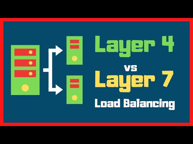
Load balancing in Layer 4 vs Layer 7 with HAPROXY Examples
176.7K
When a Layer 7 load balancer terminates TLS, it presents its own certificate to clients and decrypts traffic before forwarding it to backend servers. This allows the load balancer to inspect encrypted traffic and make routing decisions based on the decrypted content. The load balancer can also support Server Name Indication (SNI) to serve different certificates for multiple domains hosted on the same IP address.
Click to watch →

F5 101 exam workshop - part 2/3
120
SSL/TLS termination involves the Big-IP decrypting encrypted traffic to access Layer 7 content. Without termination, the Big-IP only sees encrypted data and cannot make intelligent routing decisions. With termination, the Big-IP can inspect headers, cookies, and other application data. The Big-IP can then either re-encrypt traffic for backend servers or send it unencrypted, depending on security requirements. When the Big-IP terminates SSL, it uses its own certificates for encryption, centralizing certificate management and eliminating the need to manage certificates on individual backend servers. The Big-IP can use certificates with longer validity periods than typical public certificates. For re-encryption to backend servers, the Big-IP acts as a client, negotiating SSL with each server using its own certificates. Load balancing provides three main benefits: (1) Availability - if one server fails, traffic continues to healthy servers; (2) Performance - distributing connections prevents any single server from becoming overwhelmed; (3) Scalability - applications can grow by adding more servers to the pool rather than upgrading individual servers.
Click to watch →
SSL Termination in HAProxy - HAProxy Basics
37.6K
SSL termination is the process of offloading SSL/TLS encryption and decryption from web servers to a load balancer like HAProxy, which offers benefits including reduced server workload, centralized certificate management, and enhanced security controls such as restricting supported SSL/TLS versions and cipher suites; to implement it in HAProxy, configure the frontend with SSL-enabled bind lines pointing to combined PEM certificate files, optionally redirect HTTP traffic to HTTPS using HTTP-Request redirect rules, and fine-tune security settings by specifying allowed SSL/TLS versions and ciphers, then verify the configuration using SSL Labs SSL test.
Click to watch →
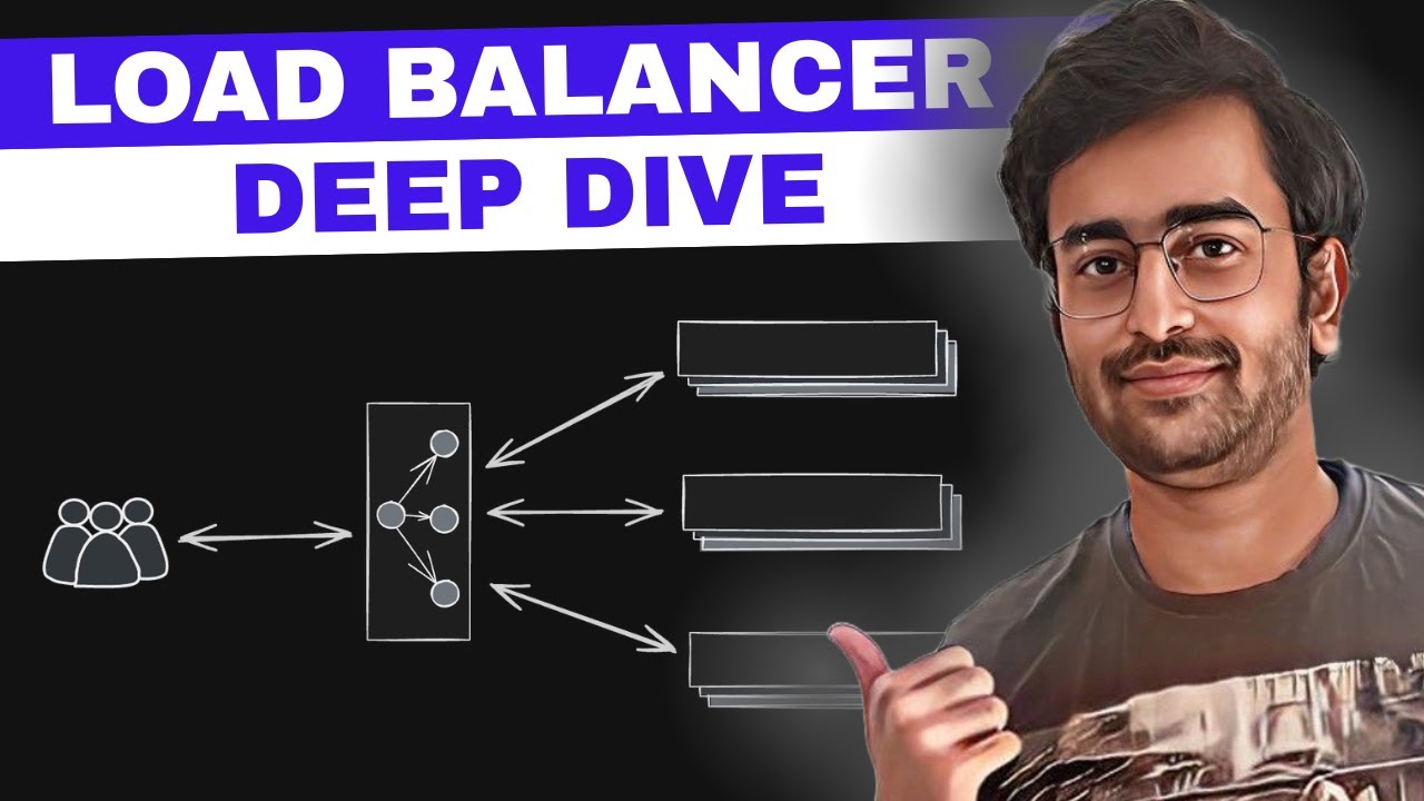
Load Balancer in System Design Interviews | L4 vs L7 Explained + Load Balancing Algorithms
1.1K
L7 load balancers operate at the application layer and terminate both TCP and TLS connections. Unlike L4 proxy mode where data remains encrypted, L7 load balancers decrypt HTTPS traffic to inspect request headers, cookies, and other content. This enables intelligent routing based on user authentication status, premium account type, or other application-specific criteria. For example, a load balancer can route premium users to dedicated high-end servers. Additionally, L7 termination simplifies certificate management since only the load balancer needs SSL certificates, eliminating the need to manage certificates on hundreds of backend servers.
Click to watch →
Introduction to OpenStack Load Balancing
1.4K
TLS termination at the load balancer provides significant performance and security benefits: backend servers avoid TLS computational overhead, certificate management simplifies to a single point of maintenance, and header inspection enables intelligent timeout handling to prevent premature connection termination. However, current implementations transmit decrypted traffic to backend servers, requiring plaintext transmission on trusted networks. The community is actively developing end-to-end re-encryption capabilities. Layer 7 processing extends these capabilities by enabling content-based routing through policies and rules that match hostnames, URL paths, or file types, allowing sophisticated traffic management like blocking malicious file types or redirecting HTTP to HTTPS.
Click to watch →
Deep Dive
Understanding service discovery and ingress routing in microservices architectures and container orchestrators like Kubernetes.

Kubernetes Networking Intro and Deep-Dive - Bowei Du & Tim Hockin, Google
81.4K
This section covers service discovery mechanisms and L7 routing in Kubernetes. Endpoints represent the actual pods behind a service, created by the endpoints controller which converts pods matching the service's label selector into an endpoints object. Endpoint Slices are a newer API that splits endpoints into smaller chunks for scalability. DNS is integral to service discovery, with CoreDNS as the default implementation running as a pod. Service names follow the format <service-name>.<namespace>.svc.cluster.local, with aliases allowing shorter names. Kube-proxy runs on every node using iptables, IPVS, or user-space mechanisms. It watches services and endpoints, applies filters, links endpoints to services, and updates node rules. No Local DNS addresses high DNS resource cost caused by name alias expansion and high application density. The solution is a slimmed-down local cache on each node based on CoreDNS, without many plugins. Ingress is a Kubernetes API for describing an HTTP proxy and routing rules, matching hostnames and URL paths to target services.
Click to watch →

What is Service Discovery?
1.5K
Service discovery is a mechanism in microservices architecture that enables services to dynamically locate and communicate with each other without hardcoding network addresses, using a two-stage process where services first register with a service registry (storing their type and network address) and then look up the addresses of other services when making requests; it can be implemented at the application level using tools like Eureka or HashiCorp Consul, or at the infrastructure level using Kubernetes, which provides built-in DNS-based service discovery that routes traffic to available instances automatically.
Click to watch →
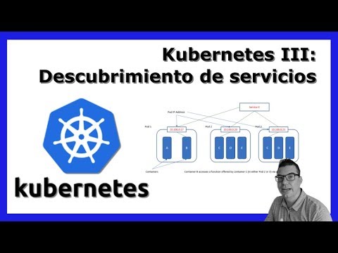
Descubrimiento de servicios en kubernetes
3.5K
In Kubernetes, microservices discover each other through a built-in DNS system that resolves service names to IP addresses, enabling containers within the same pod to communicate via shared IP addresses while different pods use service names for inter-service communication, with services exposed through ClusterIP (internal cluster access), NodePort (external access via node ports), or LoadBalancer (external load balancing).
Click to watch →

쿠버네티스 서비스와 인그레스 쉽게 이해하기!
927
In Kubernetes, Services bundle pods into a single network endpoint using ClusterIP, NodePort, or LoadBalancer types, operating at Layer 4 (TCP/UDP), while Ingress is an advanced Layer 7 controller that routes HTTP/HTTPS traffic to Services based on domain and path rules, enabling external web traffic access to internal pods through domain-based routing.
Click to watch →

Clase 15: Int a Kubernetes y Well-Architected Disaster Recovery | Karen Gonzalez & Carolina Gorosito
117
This section explains Service discovery and label-based routing in Kubernetes. Services act as load balancers, distributing incoming traffic across multiple Pods. Labels are key-value pairs attached to resources that enable organization and filtering. Selectors allow Services to identify which Pods they should route traffic to. The section explains how Services enable automatic service discovery between microservices, allowing applications to find each other without hardcoding IP addresses. This abstraction simplifies scaling and management by decoupling application code from infrastructure.
Click to watch →
L4 vs L7
L4 vs L7
0:00- 1
L4 operates at transport layer, using IP/port for forwarding.
- 2
L7 inspects content like URL, headers, and cookies for routing.
- 3
L4 prioritizes speed; L7 suits complex routing needs.
Decentralized and Client-Side Load Balancing
While traditional L4 and L7 load balancing relies on centralized middleboxes, modern cloud-native architectures increasingly favor client-side load balancing and decentralized service meshes. Grounded in the network design 'end-to-end principle,' this perspective argues that dedicated hardware or virtual load balancers introduce unnecessary latency, increased costs, and single points of failure. In client-side load balancing (such as in gRPC or Spring Cloud), the client application itself queries a service registry and routes traffic directly to an available backend instance. Additionally, service meshes utilizing technologies like eBPF shift routing decisions directly into the operating system kernel or local sidecar proxies. This decentralization bypasses the traditional L4/L7 middlebox paradigm entirely, offering superior horizontal scalability, reduced network hops, and more granular control without the bottlenecks of centralized infrastructure.
Basic understanding of the OSI (Open Systems Interconnection) model, specifically the functional differences between the Transport Layer (Layer 4) and the Application Layer (Layer 7).
Fundamental concepts of TCP/IP networking, including how IP addresses, ports, and protocols (TCP/UDP) facilitate communication.
Familiarity with web protocols, particularly HTTP and HTTPS, and how client-server communication works.
The general purpose of a load balancer in system architecture, such as achieving high availability and distributing traffic.
Practical configuration of industry-standard load balancers like NGINX, HAProxy, AWS Application Load Balancer (ALB), and Network Load Balancer (NLB).
Analysis of advanced load balancing algorithms, including Weighted Round Robin, Least Connections, and IP Hash.
Implementation of SSL/TLS termination, decryption, and certificate management at the Layer 7 load balancer level.
Understanding service discovery and ingress routing in microservices architectures and container orchestrators like Kubernetes.
74.5K views2.6Klikes1:12@arjay_the_devOriginal Release: 2025-10-17
For today's software engineering interview, please explain the difference between L4 and L7 load balancing.
>> Sure, let's start with layer four. Layer four load balancing operates at the transport layer of the OSI model. The load balancer only has access to things like what IP the request is coming from and what port number it's trying to access. Then it just forwards that packet to one of your servers, usually with a simple policy like least connections or round robin.
>> Okay, so it can't actually see the content of the request.
>> Exactly. That makes it both super fast and super secure. It can't see anything that's actually in the request.
>> And when would you use this?
>> L4 load balancing is great when our top priority is performance and we don't need to route requests based on the actual data. It's common for things like video streaming or video games.
>> Got it. How about L7? L7 load balancing happens at the application layer. The load balancer can look at things like the headers, the URL, the cookies, and even the body of the request if you want.
>> And when would you use this?
>> L7 load balancing is useful for things like microservices or APIs where you need to route requests to a specific server based on information beyond just the port number or IP. For example, if we get a specific URL and we know that has to go to a specific server, we need L7 load balancing.
>> Sounds great. Are there any downsides?
L7 load balancing takes a lot more overhead than L4 load balancing because we have to actually open up and look at each request and then make a decision about which server it goes to.
Up Next
8:22
Load Balancing Explained: Algorithms & Architecture
@IBMTechnology
309.8K views•2021-10-04

87:26
Introduction to Secure Multiparty Computation with Yehuda Lindell
@fhe_org
7.7K views•2021-02-04
4:55
HTTP Requests Explained: GET, POST, PUT, DELETE
@codecademy
103.1K views•2021-10-07

19:25
Enigma Machine Mechanics: WWII Encryption Explained
@JaredOwen
13.2M views•2021-12-11
Related Study Plans & Knowledge Roadmaps
Structured learning paths in Computer Science
computer-science
Container Runtimes: Namespaces, Cgroups & Go
01Linux Systems & Go Programming Foundations
02The Core of Isolation: Chroot and Filesystems
03Linux Namespaces: Process Isolation
+ 3 more learning modules
32h6 modules
Explore Roadmap
computer-science
Building a CHIP-8 Emulator: Rust & CPU Basics
01Computer Architecture Foundations (Bits & Bytes)
02Rust Programming for Systems Development
03CHIP-8 Virtual Hardware Specifications
+ 2 more learning modules
32h5 modules
Explore Roadmap
computer-science
Building BitTorrent: Go, P2P & Concurrency
01Go Fundamentals & Concurrency
02Networking Foundations & P2P Architecture
03Bencode Parsing & Torrent Metadata
+ 3 more learning modules
26h6 modules
Explore Roadmap
computer-science
Actor Models (C++ Concurrency & Lock-Free)
01C++ Multi-Threading Foundations
02Thread Pools and Task Scheduling
03Atomics and Lock-Free Queue Design
+ 3 more learning modules
45h6 modules
Explore Roadmap