












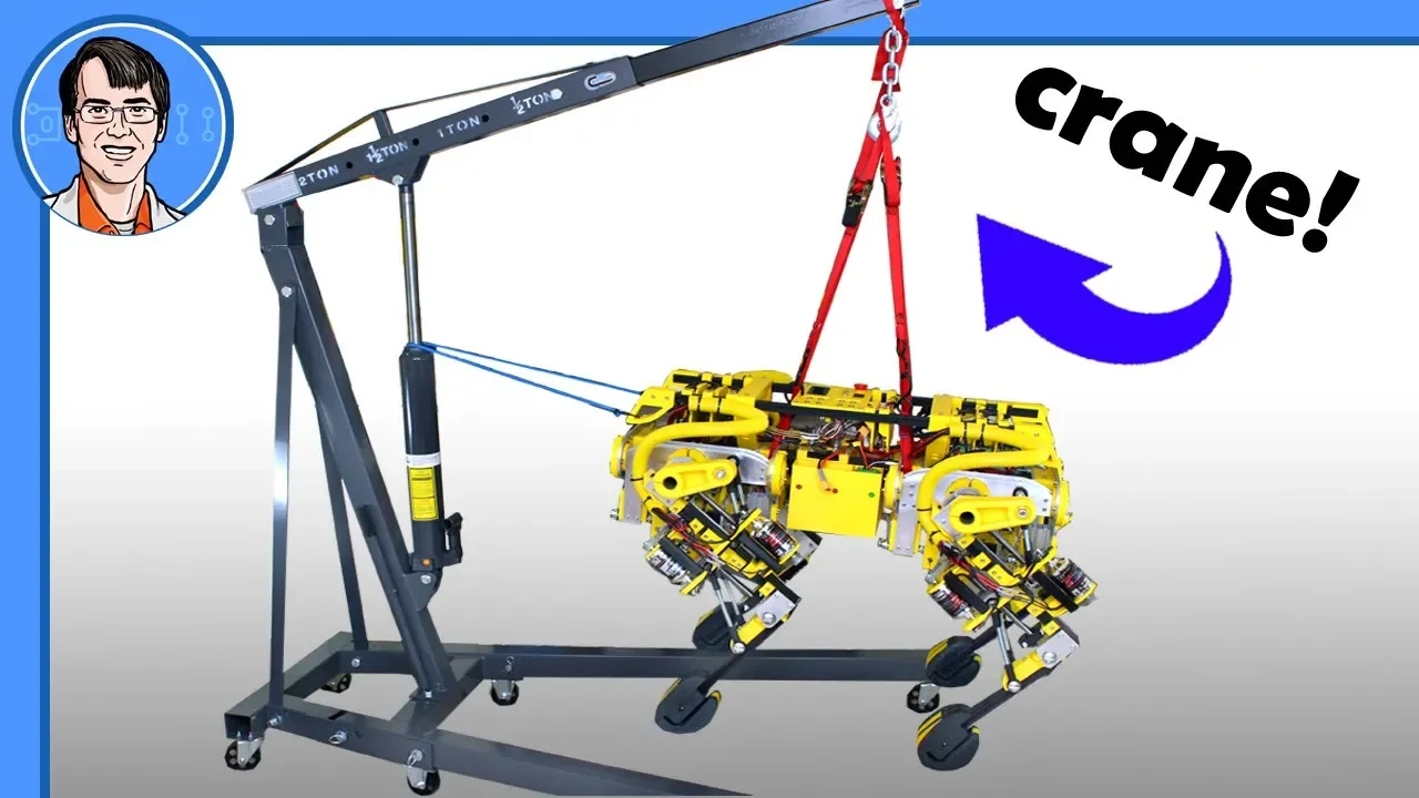







![Gerardo Bledt and Donghyun Kim: MPC and Vision Aided Dynamic Walking [ICRA 2020 WS Legged robots]](https://i.ytimg.com/vi/ZWY0vgsWnhU/maxresdefault.jpg)


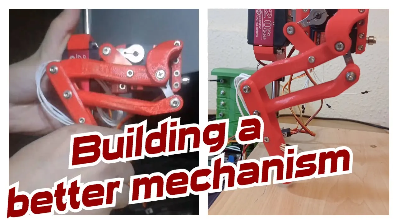

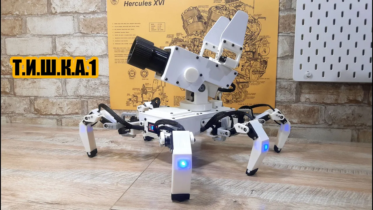


This video demonstrates how to integrate load cells with mechanical switches for robot foot sensing, enabling a rigid robot (openDog) to detect ground contact and measure pressure on each foot. The system uses a Sparkfun NAU7802 I2C load cell amplifier connected to a Teensy microcontroller, with a custom foot design containing both a load cell and a physical switch to confirm ground contact before measuring force. The project addresses the challenge of making rigid robot legs more dynamic by simulating spring behavior through real-time load feedback, which helps the robot maintain balance and respond appropriately to uneven terrain or unexpected disturbances.
Testing Load Cells & Foot Sensors for Quadruped Robot Legs
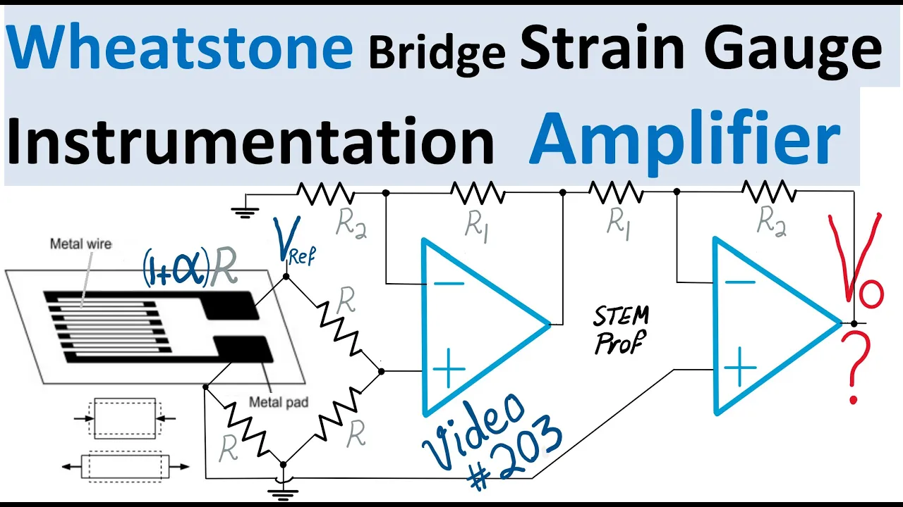
Added:Fundamentals of strain gauges and Wheatstone bridge circuits, including signal amplification (such as the HX711) used to measure physical force.
Basic microcontroller programming (C/C++) and sensor interfacing to read analog and digital inputs in real-time.
Introductory robotics concepts, specifically legged locomotion kinematics, joint torque distribution, and ground reaction forces.
Basic principles of closed-loop feedback control systems, where sensor data is used to dynamically adjust motor behavior.
Implementation of dynamic gait planning algorithms (e.g., trotting or bounding) that use real-time contact detection to trigger phase transitions.
Advanced state estimation and sensor fusion, combining foot sensor data with Inertial Measurement Unit (IMU) data using Kalman Filters.
Model Predictive Control (MPC) and Whole-Body Control (WBC) frameworks to achieve active balancing and external disturbance rejection.
Design and material selection for compliant robotic feet to absorb impact forces and improve traction across diverse terrains.
94.3K views3.3Klikes16:32Original Release: 2019-12-17
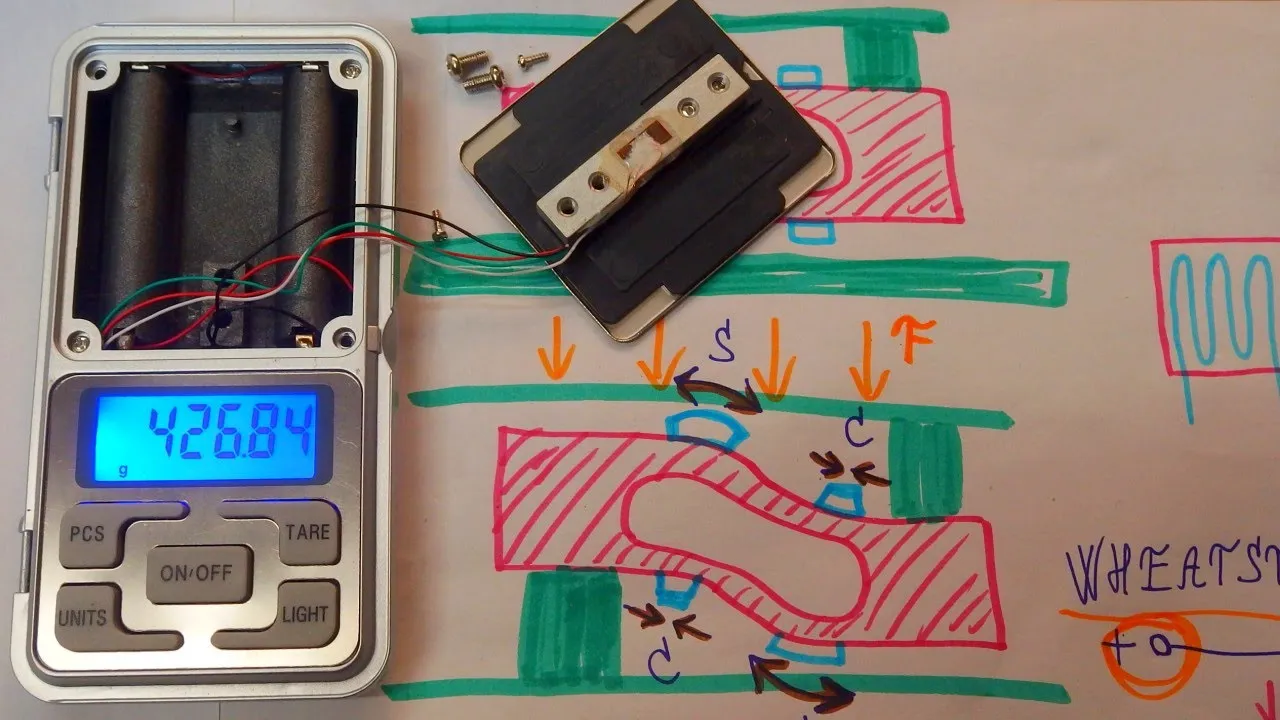
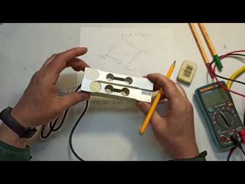
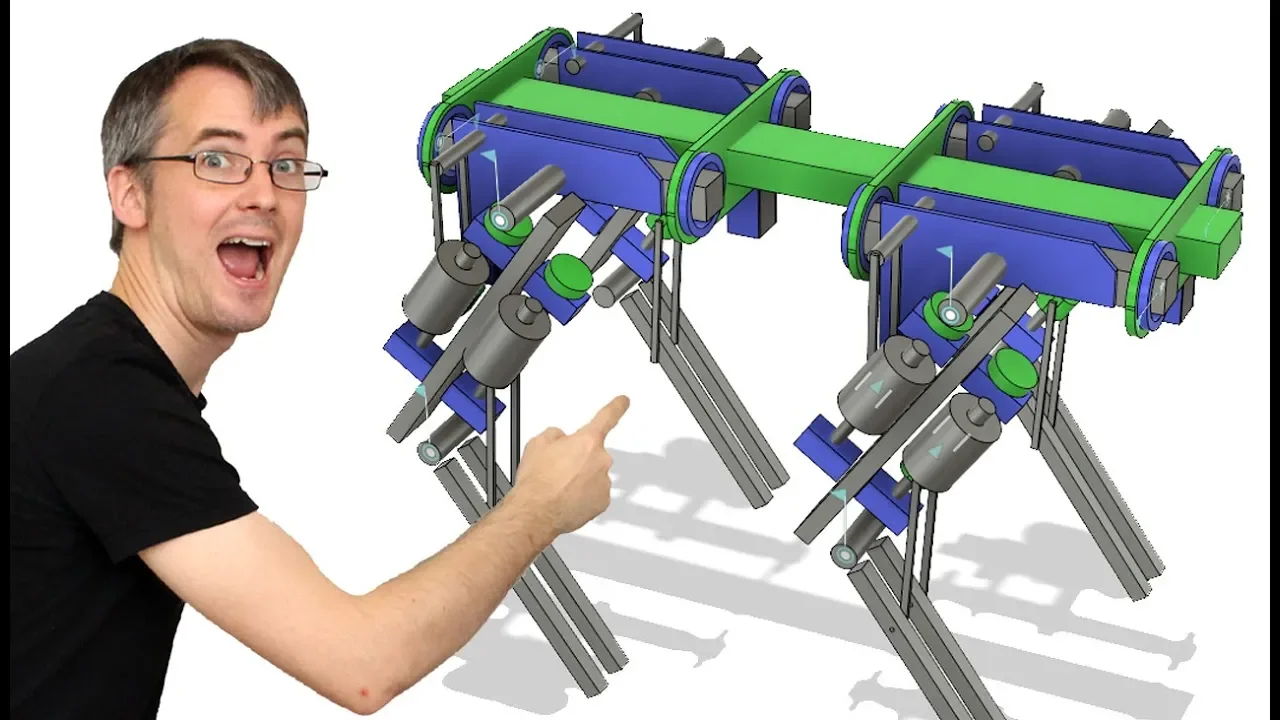
hello it's the next part of a open dog the open source quadruple robot and we're actually moving back to open dog now to do some more work on it after I take a bit of a food from the project to work on some other development dogs to see what I could learn by structuring the legs in a different way now this projects been going on for a while it's an ongoing development project and initially I thought four legs would be easy to make it work and that's because basically I made a couple of two-legged bipedal walking robots both my Star Wars gonk droid which worked pretty well that was entirely 3d printed and then I moved on to build robot X which had some metal in it and lots of 3d printing and various actuators I bought though for those want pretty much okay on two legs the only thing I didn't take into account of course was those robots had quite big feet and open dog doesn't has paws that has to balance on so if it takes more than one leg off the ground at a time then it actually has to balance on the other two legs in terms of open dog development this robot has three motors in each leg so that's 12 motors in total and there's a kinematic model that changes that complicated geometry into Cartesian coordinates so essentially I can position each foot in x y&z positions and that means the robot can move in unison so that it doesn't tear itself apart because it's quite powerful we can demonstrate that with a six axis of motion which are three rotation and three translation axis I also have some interpolation which means I can move those joints all those feet at least in straight lines through space from point A to point B by interpolating through all the positions on the way and that means that even though the motors and the geometry might run at different speeds with different axis we can still get that foot to an end point of all the motors stopping at one point now I have built in some sense of stability to this dog using an inertial measurement unit they can measure the tip in either direction and I can try and use that to balance as it takes two legs off the ground now you'll notice with a real dog that's not how they walk Tony generally a slow walking pace take one foot off the ground and keep a triangle now I did try and do this early on with opened dog Denise's shift a significant amount of mass over to one side in order to take that foot off the ground without falling down and that's pretty clunky if you look at Boston Dynamics all the MIT cheetah dogs you'll notice they take diagonal legs off the ground to keep balanced and that's called a trot gait and that's prob what I'm gonna attempt with this dog now I did get quite a way of trying to keep it balanced it can do it for quite a long time walking on the spot taking diagonal legs off the ground but if it goes slightly wrong then basically it means it pushes down with a really rigid leg because these legs are driven by ball screws there's no natural spring in them and that causes everything to go wrong so I then thought I should investigate what if the legs were slightly springy would that be more forgiving and it less likely to go completely wrong if basically it doesn't stay perfectly balanced which is quite a hard thing to do so I built some test legs and some test dogs which had the leg structured in a different way I didn't want to rebuild this one with Springs in it and Springs anyway are quite unpredictable and that's their dampened and controlled mechanically so I decided to build simulated Springs with back drivable gearboxes and some holding Tonk and also a controller that would allow that foot to catch up to a position you push it to so we can make that spring slightly softer encode in real-time as the dog tips and the way it worked was basically if it's tied to tipped to one side we softened off the other legs to bring it back and if it tipped the other way we softened up those legs and in the end we managed to keep it working essentially perpetually until you ran out of power walking on the spot and you can see the legs are quite spongy and that's quite forgiving and that works out quite well open dog though is not spongy and forgiving it's incredibly rigid it's driven by ball screws and that means that basically it's gonna put its foot where you tell it to and that means we have to control it incredibly well we can assume the ground is flat but that means the balance has to be absolutely perfect so nothing weird happens if a foot goes down and the dogs tip slightly more than I thought it did all the code can't control it properly so what I'd like to do is make these dogs legs more spongy and forgiving like the test dogs but actually we've got a really rigid dog so that means we're going to have to try and simulate a spring with a rigid actuator so what we're going to need is some sort of foot pressure sensor that we can sense pressure and we can make the leg react accordingly so I have got these feet on you'll see you've got a piece that closes I was planning to put a pressure sensor in in the future however I don't think this is going to be very repeatable it's just one 3d print and also it's really hard to determine whether it's definitely on the ground or not depending on whether there's other load on the other feet so we're gonna need another solution so we're gonna have to make some heavy-duty analog sensors I think I'm gonna have a switch as well so it knows the foots definitely on the ground when it is on the ground we need to get some sort of load measurement so in the past I've used sort of Springs and Hall effect sensors and magnets and a Hall effect sensor will sense the distance from a magnet we can just read that with an analog in on an Arduino or whatever but I think we're gonna need something pretty heavy-duty because whatever the springs are in that case would have to take the load of the dog on two feet at the minimum that's quite a strong spring to still get quite a linear measurement with fall sensitive resistors of course aren't linear and we found that in the past so we can have to try something else and so we're gonna have a go with a load cell and this is basically one of the load cells I got Amazon here it's basically a block of metal with some strain gauges on each side it's got a little amplifier board and we can plug vane to an Arduino there is a spark fun electronics hookup guide for this which details various strain gauges and load cells which you can of course buy from them as well this is similar to the one I have here and what you're supposed to do as we can see in this picture is attach one side of it to a plate and another side of it to another plate and then basis queue it and it measures the load on the piece where the holes are so there's various alva so you can hang on a hook and so on and of course there's a hook up guide with the amplifier board for an Arduino and there's also some sample code here down the bottom the code is pretty simple we've just defined two pins there for it to be linked to one for data and one for clock and we've initialized the library and everything and we've got a 0 here which happens on startup so that it's zeroed and we can run that at any point I guess and then we're just going to go write those values to the serial terminal so we should find it starts outputting zero pounds now there is a calibration sketch I haven't run it so I'm not sure that my scale is accurate but if I start skewing this we should be to see that we get some some results there so as I skew that that was an Ford's we should find that we get positive and negative swing I'm not sure if I'm applying that much force to it I don't think I am also twisting it slightly tends to work as well if I twist that we should be to see that we've got some sort of answers there so if that seems pretty good I'm not sure if I can put the whole load of the dog on this piece of metal here this is one is rated at 20 kilograms I'm pretty sure I can so we're gonna need to come up with some sort of shunt solution so I've bolted that onto a piece of 20 40 extrusion in fact which is the same as the lower part of opened dog's leg and I've got some spacers in there because we've got the strain gauges bonded on there's a little gap there's just lots of washers stacked up it's not a particularly good job and there's two m4s and two m5s the loads that is actually tapped for those really I could do have nuts on the top as well to hold that nice and tight so they don't come undone below didn't have any bumps long enough but it'll do for now in my code I've changed the calibration factor 250 from minus seven thousand and fifty which is 70 thousand and fifty which is where it was before and apart from that I've done nothing and this scaling factor gives it a much more sensitivity so we get much higher values so now if I bend this whole piece of aluminium which should be to see we get a really big value then if I bend it the other way of course it goes negative and of course this bit of aluminium is really rigid so hopefully it will never creep I've not noticed these bending in opened dogs so they support the weight of the dog okay but it doesn't put all the load onto the load set all the strain gauge there so we can see we get that value but it's unlikely this is going to get deformed hopefully as long as this is rigid which it pretty much is and we already know that takes the load of the dog so of course we could just get those and put them on each leg that's exactly the same as the lower leg of open dog so we could put that down there that would fit nicely in between the pivot points and the foot that we've gone there and then we can measure the pressure on each foot and we can make the legs of reacts accordingly what I really want to do though is be very sure that the foot is on the ground or not on the ground so I'm gonna make a new foot that's actually got a physical switching with a spring that doesn't have to be very strong that Springs that switch open so when it is on the ground we know it definitely is and we can start measuring that force and when it's off the grounds we just ignore the data and we can also use that to calibrate the zero point because we know there's no load on it so I've taken the old foot design and designed a completely new foot and this is different because instead of one piece with a flexible section we've got two pieces with an actual pivot in there so there's a joint and that will allow the foot to and close of course with the weight of the dog on it will close right up to its end stop and that'll switch the switch and without the dog we can put a spring in to push it apart now I've left the same space for the flexible ninjaflex filament to be fitted in there and hopefully that should actually act partially as the spring and to also stop up foot falling completely open so let's get those printed and see how well it works [Music] so here are the new and old feet this is of course the new one this is the original one the original arm was printed in ninja tech armadillo which is an incredibly tough rigid TPU material so that's got really good layer bonding and there's absolutely no sign of splitting or anything on that even with the load of the whole dog on the dog weighs about 50 kilograms so this one is just prototypes in PLA I'll probably go on to print it in armadillo again but for now this will do for testing so of course we've got that pivot in there and as I mentioned the whole thing will just fall open so I'm going to get the ninja flex flex it will strip out of here screw that back in here and see how that performs I've installed that piece of ninja flicks around there and that's screwed on the front on the back so that now helps act a bit like a spring and it stops it falling back a bit but not quite enough really so I need to constrain that a little bit more when the dog picks his feet up I put some screw holes in here so he might just put a piece of elastic or something around the leg for now this is only the prototype in the proper one I might do something else like a hard end stop on the front where this gap is so I've installed the switch as well as you can see there and that's the hard stop so the focus isn't on the switch itself it's on the back of this because it can't shut anymore so that'll tell me when the foot is definitely on the ground and that works of course from any angle that the foot comes down so that seems to be pretty good and of course the dog's leg fits in here with a load cell on the leg there so then once that switch is pressed we can start measuring that analog sensor so I've now got my leg belt with the actual piece of extrusion from open dog with the load cell fitted with nuts on the top and I call the switch fitted which is now going to a teensy 3.2 which is going to run all the data from this I've had to change the am board here the original board would only give me data around 11 times a second so I've upgraded that to a spark Vaughn NAU 70802 which we've got to 320 times a second and it's an I squared C device which is a standard interface the code for that is pretty simple we just use the library and to read the raw data we just through my scale get reading and I've done some threshold into account the switch then we've got installed so we don't get any value until the switch is pressed we can also use that switch of call so we know when the foot is on the ground and perhaps there are zero calibration of the whole thing in the serial monitor we can see the switch value and we can see the reading so if I've been this leg without the switch pressed we get nothing until the switch is pressed and then we get some sort of value at the moment I throttled it to 200 samples a second but that seems pretty responsive let's have a look at a serial plotter so we can see that's a bit spiky in my need filtering but overall we get a good range of values so it looks pretty hacky but I've just attached everything to the leg here so we can do some testing of course this whole project is R&D really so that's my load cell where we've got our switch in the foot we've got the amp board and we still got a teensy three here on a piece of bread board and the reason for that is that we can't read ress the I squared C address of these amp boards unfortunately so we're gonna need a kind of shim micro controller that deals with this it could also deal with zero calibration on startup each time etc and then that's going to send the data over to the main microcontroller for the dog and that part is really hacky as well as on this gray cable that's just temporarily looped all the way up here this is a shielded cable ideally I need some sort of data interface that would actually send data from one Arduino or one teensy to the other but I'm out of serial ports what I really need is CANbus which I need to investigate and I've never used before so for now I'm sending the data well as PWM so I'm actually writing out a PWM signal on the teensy down here and reading it back in with interrupts on the teensy three point six in the dog so what we're now looking at is a graph of the actual load cell where of course working quite nicely and that data is coming off the teensy 3.6 in the main dog body having been sent from the teensy on the leg all the way over with PWM and I'm reading that Cygnus I say with interrupts so I've got quite an accurate responsive answer there which is quite good and obviously when I let go the switch it drops back to zero so that seems to be working pretty well but now let's see if we can make the leg respond so unfortunately as you can see I've powered the motors up what we've actually got I think you can even see the data there is a really bad spikey signal which is basically down to these motors being high-power three-phase motors even just with holding power on as if I move the motor we can see extra spikes on the signal great and that's basically inducing some voltage of course into the signal wire there despite being shielded obviously that's not enough to help me so we really are going to have to investigate some sort of other data interface here because this really really is useless data now obviously due to the motors being powered up and the crosstalk in the cables obviously if I power off the brushless motors then everything's good and it's back to normal again with the proper signal so we can see how high those spikes are actually relative to the spikes that we've got now we let the serial plotter rescale itself yeah so that's back to normal now so they really are big spikes they're even bigger than the signal why should nobody be sending so sorry this video is not more exciting I was hoping to actually have that leg at least responding so next time we could do it on four legs and hopefully make the dog more dynamic we can have to investigate CANbus which is a differential signal and that's used in automotive applications so should automatically cancel that noise out on the line and give us much better data and that's a much better way to do things anyway that is something I've not looked at before so I'm gonna have to investigate that in the next video and we'll come back and hopefully work that in now lots of things in this project it is an ongoing R&D project we're on about part 20 here a lot of those things have been using up a project so I've learned quite a lot going along doing the project as I've done it so the brushless motors and drives and all of that have being used in performance robots the first of all the fields are that smoothes out makes all the motions smooth has been used in multiple other projects as well as obviously CNC aluminium and the mechanical construction and everything else so load cells will definitely be using up a project sound looks like quite a way good way to do things to do full sniffing joints and to make things dynamic and of course canvas will be as well so that's a really good thing to investigate at this point not only will it benefit this project but will benefit other projects in my channel so don't forget to subscribe for more updates on this and lots of other ongoing projects if you want to support the channel then please look at my patreon it's patreon.com slash x robots and also have youtube channel membership if you don't like patreon and of course I do have a merchandise store I do have new performance robots t-shirts which have just come out as well as the good old favourite opened dog and also have mugs bag stickers and various other products alright that is all for now [Music]
Up Next
19:30
ESP32 Multitasking with DRV8825 Stepper Motor Drivers
@pcbreflux
33.4K views•2017-06-22

12:54
Triumph of Orthodoxy Icon: Byzantine Art & History Explained
@BenCallan
2.1K views•2024-08-06

17:29
Active Omni-Wheel Design and Mechanics for Two-Axis Control
@jamesbruton
2.8M views•2022-02-01

1:42
Game of Thrones Opening Credits: A Cinematic Analysis
@gameofthrones
46.3M views•2011-04-18
Related Study Plans & Knowledge Roadmaps
Structured learning paths in General & Interdisciplinary Studies
general-studies
Elevator Engineering: History, Physics & Cities
01From Hoists to Safety Brakes: The Dawn of Vertical Lift
02Hydraulic vs. Traction: The Engineering Physics of Elevators
03Modern Speed, Safety, and Algorithms
+ 2 more learning modules
12h5 modules
Explore Roadmap
general-studies
Rubber: Material Science, History & Geopolitics
01Origins of Natural Rubber & Mesoamerican History
02The Chemistry of Natural Rubber & Vulcanization
03The Geopolitics of the Rubber Boom & Colonization
+ 2 more learning modules
12h5 modules
Explore Roadmap
general-studies
Containerization: Evolution, Logistics & Trade
01Ancient Trade & Bulk Cargo: Amphorae to Barrels
02The Industrial Revolution & Cardboard Packaging
03The Containerization Revolution: Malcom McLean
+ 2 more learning modules
12h5 modules
Explore Roadmap
general-studies
Textile Tech: Evolution, Labor & Global Impact
01Pre-Industrial Textiles: Handloom & Cottage Industry
02Mechanization: The Spinning Jenny to the Power Loom
03The Factory System & Global Labor Transformation
+ 2 more learning modules
10h5 modules
Explore Roadmap