













![[아두이노#415] (Websocket#11) 웹소켓과 MQTT를 연동하는 사물인터넷 예제만들기!(녹칸다/포로리야공대가자)](https://i.ytimg.com/vi/X7oSkRz_ztA/maxresdefault.jpg)
![[아두이노#424] ESP8266과 웹소켓으로 nema17 스탭모터 2개를 동시에 원격제어하는 방법!(녹칸다/포로리야공대가자)](https://i.ytimg.com/vi/Ci6HmvkOMoY/maxresdefault.jpg)
![[아두이노#283] (NODERED#19) 각도제어/서보모터(SG90)/스탭모터(28BYJ-48) (사물인터넷IoT와 MQTT를 이용한 시리즈/녹칸다/포로리야공대가자)](https://i.ytimg.com/vi/9aE_P00XJ94/maxresdefault.jpg)


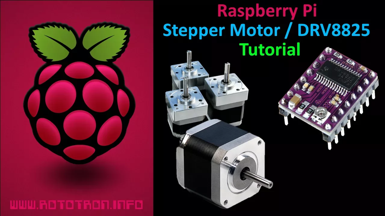
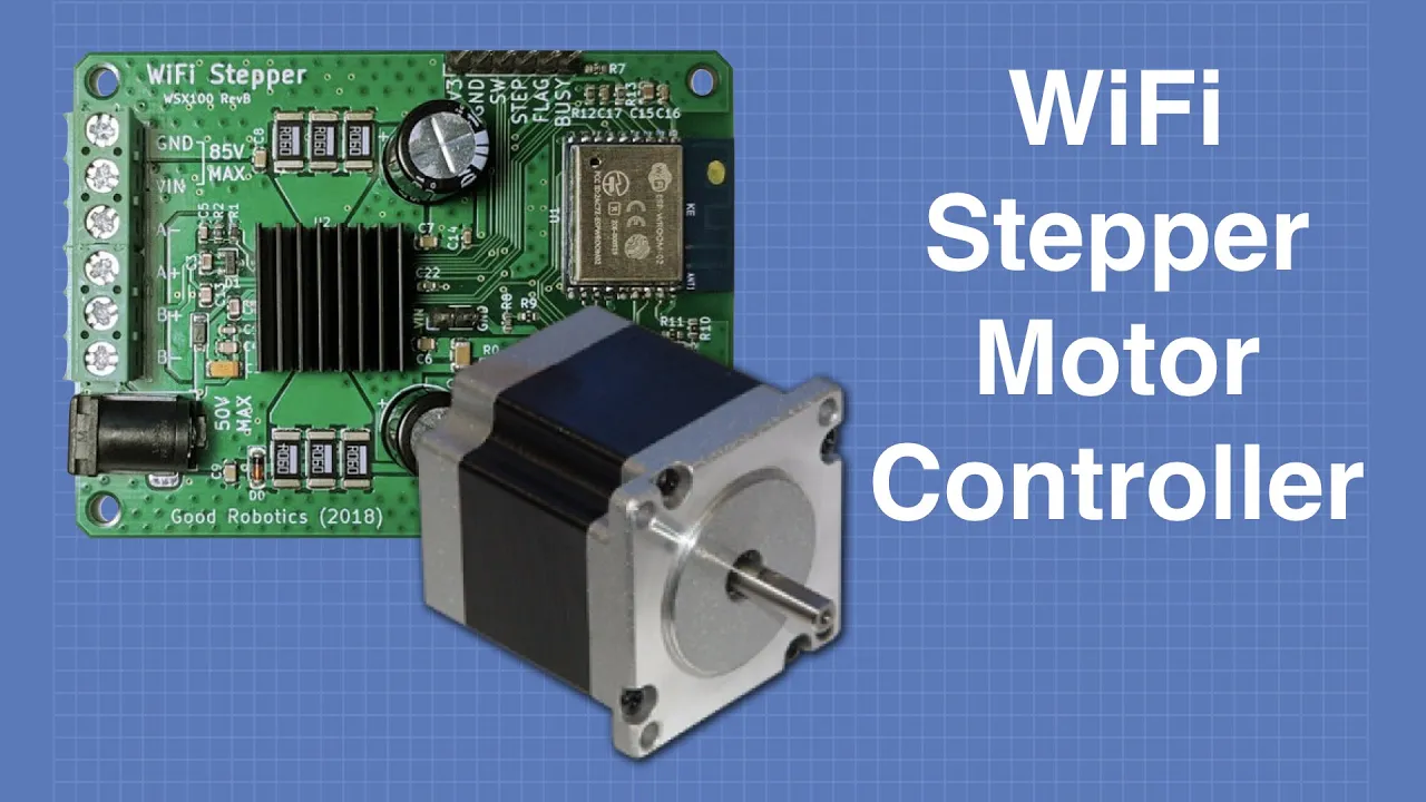
This video demonstrates how to implement multitasking on the ESP32 microcontroller to simultaneously control two stepper motors using DRV8825 drivers, utilizing FreeRTOS event groups and queues for synchronization. The DRV8825 driver requires calibration of the reference voltage (Vref) using the built-in potentiometer, where Vref divided by 0.5 ohms equals twice the maximum current. The driver supports different stepping modes including full-step (1 microstep per step) and 32x microstepping (dividing each full step into 32 microsteps). For a motor requiring 200 full steps per rotation, 32x microstepping increases the total steps to 6,400. The ESP32 uses three pins per DRV8825: step (for triggering steps), direction (for rotation direction), and enable (to lock or unlock the motor). The enable pin keeps the rotor fixed when disabled, which is useful for 3D printer applications. The video shows how to wire up two stepper motors, calibrate current, and implement concurrent motor control using FreeRTOS tasks, event groups, and queues to ensure synchronized operation.
ESP32 Multitasking with DRV8825 Stepper Motor Drivers
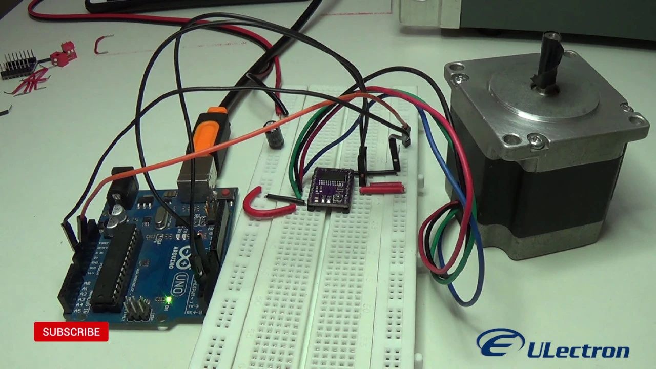
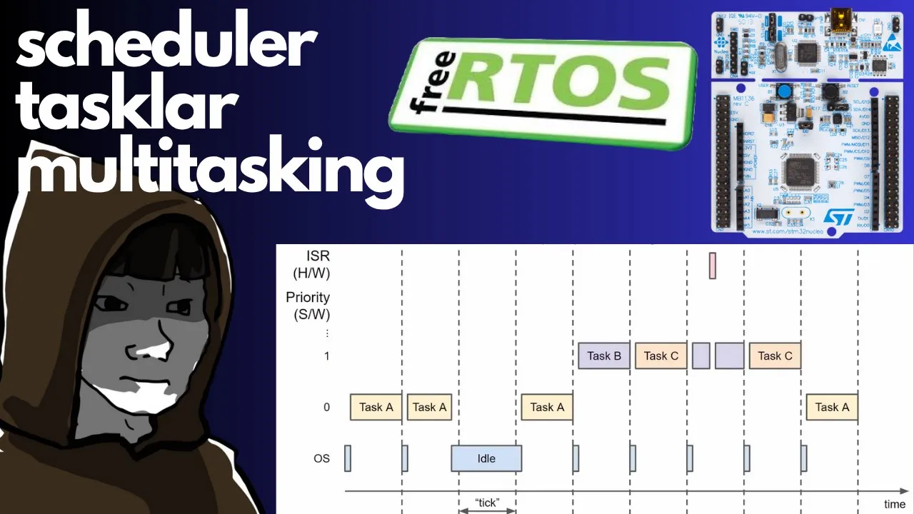
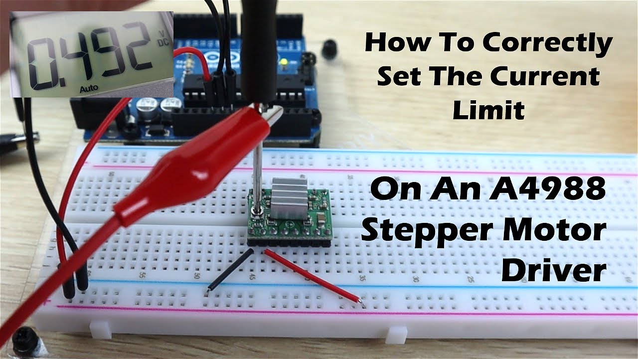
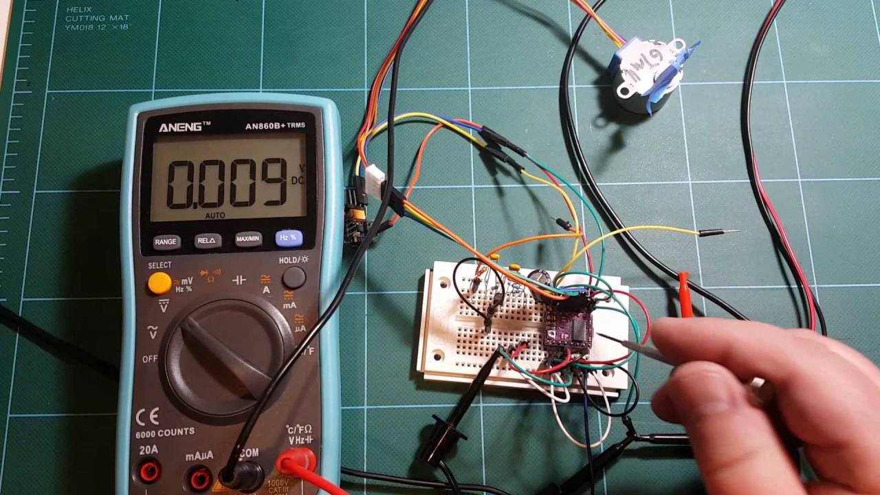
Added:hi today I want to talk about the esp32 multitasking and also driving of stepper Motors and for the example I using a stepper motor driver the drv 8825 from Texas Instruments and if you search on common selling platforms like eBay or AliExpress you find the chip in a common used module and this module is mostly used in driving stepper motors for 3D printers and so we can buy this module very cheaply and before we start with the module we have to calibrate the stepper motor current and the modules have an built-in variable resistor potentiometer and on my board there there are two sense resistors for the two stepper motor coils and they have an value of 0.1 ohm and in the data sheet we find in Formula we have the maximum current we can drive our stepper Motors I chop and this is referentia to the reference voltage and we divide this by five times the sensing resistor so our formula goes about vref divided by 0.5 ohms and this is equal to 2 * the voltage reverence so we can measure the voltage rence maybe within multimeter and tweak the value to the needed stepper motor current so then we can wire up the stepper motor and I'm using 24 volts because the currents are related to the power to the stepper Motors and if we use an higher voltage then we can use an lower current by having the same power so but we also need the 3.3 rails from the esp32 development board and we have to tie some pins and the minimal setup we have to use is to tie the reset and the Sleep pin to 3.3 Vol then we can wire up the stepper mode M and the stepper motor have two coils and we can use our multimat and if the resistance between two wires is in the range of maybe 1 to 0 ohms then we are sure that this is the coil then we can wire up the first coil to the first outputs of the stepper Motors and the second coil to the second output and the only thing we can mess up is maybe the direction of the stepper motor and we can easily change this by switching the two coils and then everything is okay next I use the GPI pin 21 for the enable pin to enable the whole driver chip and the difference between disabling the driver and enabling is that the rotor of the stepper motor is fixed while driving the stepper motor and if we disable the chip then you can freely spin the rotor of the stepper motor but maybe for stepping in a 3D printer it's very helpful that a stepper motor don't swing around and is fixed to one position while not moving next I use uh GPI open for the stepping and the stepping is just an change between low and high state of the GPI pin and every change of the polarity of the GPI pin is interpreted as an step for the stepper motor same is for the direction if we want to spin the motor in One Direction we have to drive the direction pin to low and if we want to drive the stepper motor in the opposite direction we have to put the High State on the direction pin and last but not least we have three modify pins for some different modes and we can read in the data sheet that we can put every three mode pins to low then we have a full step motor driver with one micro rotation for one step and we can also drive all the modified pins to high and then we have a 32 times micro stepping mode and this divides a full step by 32 and we have the rotation angle also divided by 32 in my case I have an stepper motor that needs 200 full steps for one rotation and so we have if we use the 32 times micro stepping then we increase the number of steps to 6,000 400 so this is 32 * 200 so enough waffling around this is my setup for two stepper motors with the esp32 and two drv 8825 stepper motor drivers and I'm using the lap power supply for the 24 Vols output for the stepper motor and the drivers and as you see they rotate at the same same time and I'm using multitasking to drive one stepper motor per task and I show later the source code for doing this but before we drive deeper into the code I use my multimeter to show you the calibration and I'm just hook the ground pin to the ground of the whole circuit and I'm using the red probe to probe the metal case of the potentiometer so on the One driver I have round about 400 molt and the same on the other driver but with a small potentiometer this not so easy to to set up because if you just rotate a micro millim the whole the whole reading is up or down 100 Mt so just be aware this is take some time to do a accurate measurement then then I can show you the difference between the 32 times micro stepping and uh maybe and I'm just change the mode wires from 3.3 volt to maybe ground or opposite and you can see the whole steep Motors are now rotating very fast but it depends on your us case if you want a very precise but slow speed and a high torque maybe or you need an very fast setup and you don't care about precision and it's okay that maybe you you lose some steps on driving your stepper [Music] Motors and today you can also win another analog lamp.com esp32 development board or module giveaway just read the terms and conditions in the video or inside the description okay let's have a look into the code and first first I show the basics of driving the stepper Motors and we just initialize some GPI o pins for our two stepper Motors and I'm using three pins per drv 8825 driver this is the step pin the direction pin and also the enable pin and the same for the second motour and if we look into our setup function we just initialize the GPI opin and set them in a default State and if we skip all the other functionality we have two calls for stepping our single stepper motor and we use motor one goes 1,600 steps in One Direction and with a delay of 200 micros seconds the same for stepper motor 2 same steps and same delay and then we just do this in a loop so let's have a look into the basic functions for the stepper motor and this is this function in on the top of our code and we just set some internal GPI open pins related to the motor number and then we just do some debug output write the enable pin to low so we enable the driver then we decide if the steps are above zero then we have a positive steps then we but this is dependent depending on your setup so my case I driving the stepper Motors counterclockwise and so we set the direction pin to high and the same if the steps are negative then we drive the stepper motor clockwise and we set the direction pin to low then we just take the absolute value from the steps so we have no sign and we do some debug output just for every step we write the step pin too high wait some micros seconds and then we write the step GPO pin to low and then also we wait some micros seconds and because our esp32 is very fast with 240 mahz so we can just use a standard aduino code to drive our pins and don't need to use fancy gpio register or so so this is the stepping of without any task and as you may see with this code we cannot drive more than one motor in the same time so if we want to drive more than one motor in the same time then we have to do some maybe multitasking or timer chopping or what have you and in my case I use for the example the multitasking so we have some preparing to use the multitasking and I use some event bits for the event group and also I use two cues to cue the orders for cue the stepping orders for the stepper motor and I have two cues the queue for the motor one and the Q for the motor 2 and as mentioned the event group and this is necessary to do some synchronizing so let's have a look at the setup function and all we do is create two cues and I just use a size of 10 but you can use other maybe we just use one order at a time so the lower number is also okay then we create our event group and this is for synchronizing and I discuss this later and then I just start to step on motor task that wait for the orders in the queue and just wait until there is a there is a order stepping order in the queue so next we watch our Loop function and this is the function we used to drive the two stepper Motors and we have just an number of steps and also the direction if it's positive then we have a counterclockwise and if it's negative we have an clockwise rotation then we use the delay in milliseconds this time because the free arour is a little bit slow so maybe if we want to use a highspeed stepper motor driver we have to use a different method but for this example I use the smallest speed in milliseconds and then the same for the second motor some steps and a direction and also a delay and the delay is propor itional to the speed of the stepping so then we have another order for the stepper Motors and a third order and then the whole thing is run in a loop so let's have a look into this function and as mentioned we have four parameters and the first two parameters are for motor one and the second are for motor number two and I set up a structure for the two Motors to give the whole structure in as an order into the queue and this is this structure the motor sent structure and we can have a look this this is in the top and this have only two parameters uh integer for the steps and an unsigned integer 32 bits this is the delays in milliseconds and then we just fill the structure and send the structure to the queue from motor 1 this is the order for motor 1 and we wait up to 1 second to place the order into the queue and the same for the second motor we just place the second order into the second que and also wait up to 1 second to place the order and then we only waiting for the synchronizing and the synchronizing just waits for two bits in the event group and if all two bits are seted then the weight function is released or if we wait more than 60 seconds then also this event function is is released but then we can check the return value and if the return value is or two bits then we know okay everything is okay the stepping of the motor is over and we know the function is synchronized and if not we know our our 60 seconds are over and and we wait again for the whole Loop so then we just wait another 60 seconds but if something wrong with our queue maybe if there's the one task is not responding then we break the whole function and know there's some error maybe so let's have a look into the running tasks that waits for the orders and this is this function and on Startup we just get an parameter and the parameter indicates the number of the motor and we have one task number one for the first motor and task number two for the second motor and then we do nearly the same without task we set our GPI oins for the given motor and we just wait for the event queue if there's a new order for this motor and if if so we just get our steps and the delay in milliseconds do some debugging setting our enable pin set the direction pin if our steps is positive then in One Direction if it's negative in the other direction then we get our step and get without the sign the absolute value do some debugging and just Loop the steps into our GPI pins and set the step pin to high wait the wait time in milliseconds set it to low and waits another time and so on until we reach the end of the steps and then we just set the event group bits if it's motor 2 we set the second bit and if it's motor one we set the first first bit and then we go to the loop forever so if there's no order we just wait 100 milliseconds for the next order is just some delay to give the CPU some time to do the other tasks so and that's it and here a small EP for my TMC 2100 chips unfortunately I've Grill them with 24 WS on the reference pin and the Magic Smoke escapes from the Chip And until then there's no steering with my stepper motor so I have to order more of the chips but this takes up to six weeks to deliver because I'm a little bit cheap and I just order from the cheapest seller in the world so I hope you find this interesting and hopefully learn something and maybe if you do so give me a big thumbs up for this video to support my work I wish you a nice day see you next time and [Music] bye-bye
Up Next

ESP32 Web-Based Touch Interface for Motorized Vehicle Control
@GadgetWorkbench
4.4K views•2018-06-27

Triumph of Orthodoxy Icon: Byzantine Art & History Explained
@BenCallan
2.1K views•2024-08-06

FastAPI vs Flask vs Django: Choosing the Right Python Web Framework
@TechWithTim
302.5K views•2024-05-26

Game of Thrones Opening Credits: A Cinematic Analysis
@gameofthrones
46.3M views•2011-04-18
Related Study Plans & Knowledge Roadmaps
Structured learning paths in General & Interdisciplinary Studies