




![KESEIMBANGAN DAN GERAK ROTASI | KELAS XI | FISIKA ITU MUDAH [Dzakia Maryani Putri]](https://i.ytimg.com/vi/DiEgL0tMjec/sddefault.jpg)


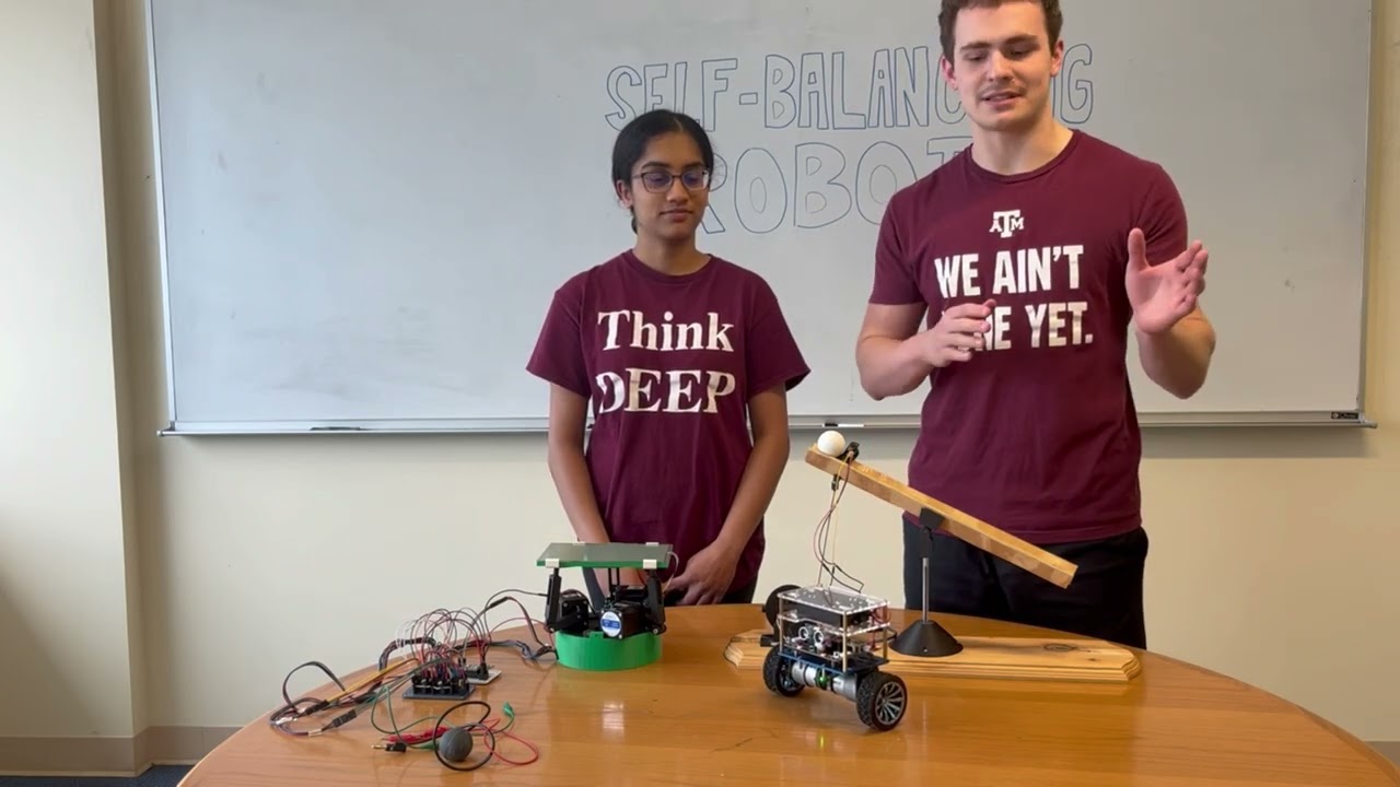

![PID Control: Arduino Self-Balancing Robot [💥SUBSCRIBE💥]](https://i.ytimg.com/vi_webp/EEnSDy4PouE/maxresdefault.webp)
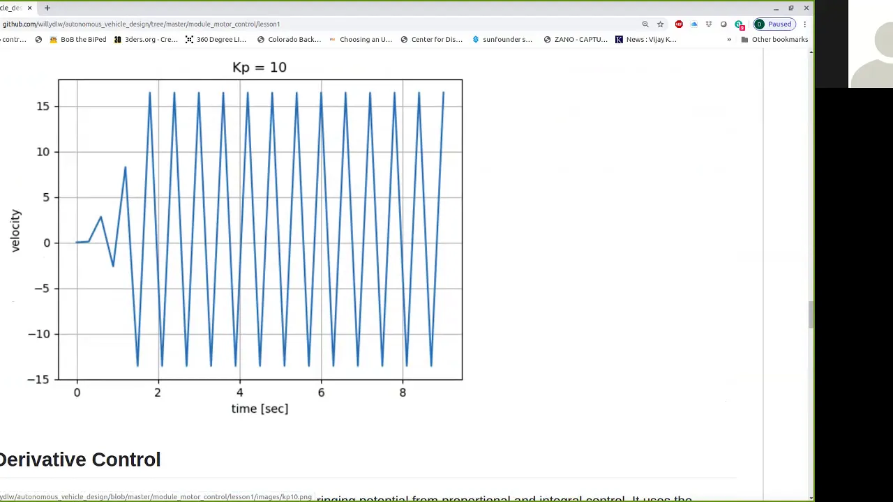


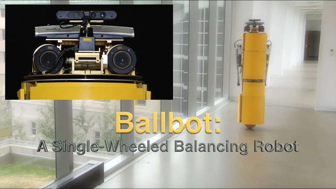




![[나합격 컴퓨터응용선반밀링기능사] PART 02 기계요소 Chapter 03 전동용 기계요소](https://i.ytimg.com/vi/ZEmfTde1z5w/maxresdefault.jpg)





![[IPO IR] 티엑스알로보틱스 - 로봇 및 물류 자동화 토탈 솔루션 전문기업](https://i.ytimg.com/vi_webp/TRLLxwgw1jI/maxresdefault.webp)
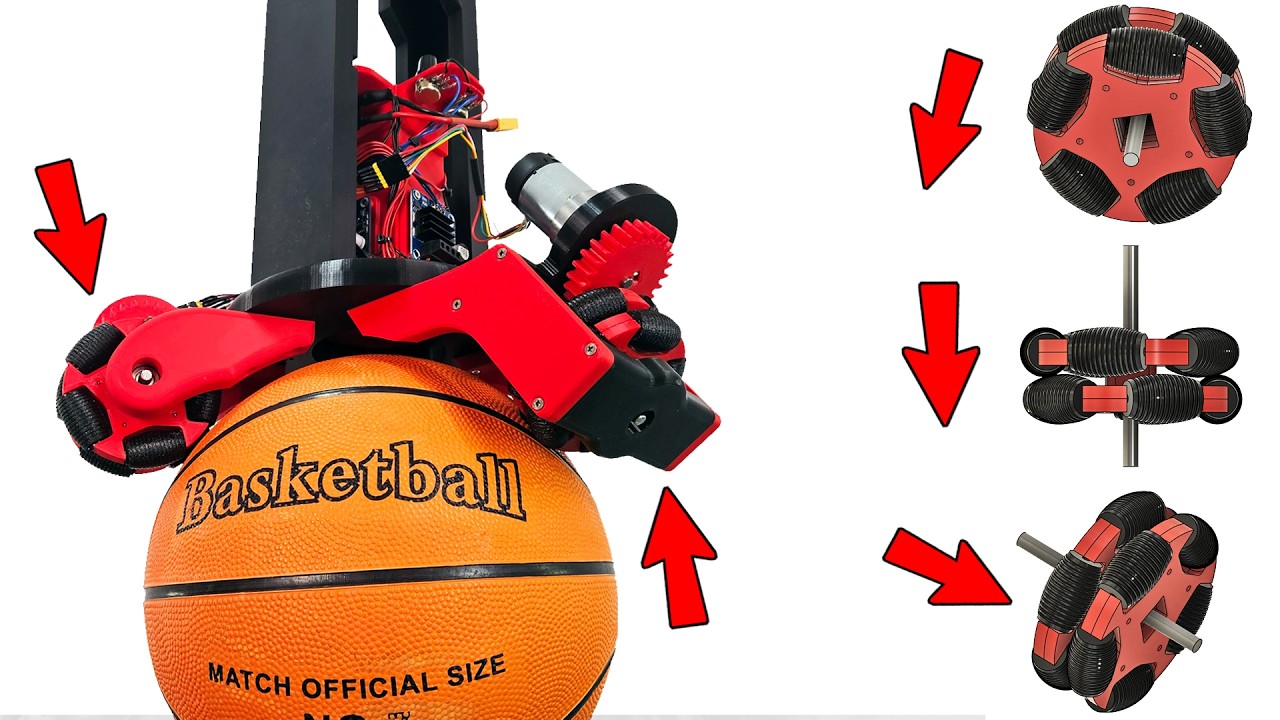
An actively driven omni-wheel achieves two-axis robot balance by using two motors in a differential drive configuration; when both motors rotate in the same direction, the entire wheel rotates normally, but when they rotate in opposing directions or at different speeds, the smaller wheels around the circumference rotate, allowing the robot to balance and move in any direction on a single point.
Active Omni-Wheel Design and Mechanics for Two-Axis Control
Added:Fundamental kinematics of standard omnidirectional wheels (passive rollers) and holonomic drive configurations.
Basic principles of rotational dynamics, torque, and rigid body motion in two-axis coordinate systems.
Core concepts of motor actuation, gear transmissions, and angular velocity vector resolution.
Introductory control theory, specifically feedback loops used in stabilizing self-balancing robotic platforms.
Advanced control algorithms for ballbots (spherical inverted pendulums) utilizing active omni-wheels for stabilization.
Mechanical design optimization techniques for minimizing slip, friction, and backlash in driven peripheral roller assemblies.
Trajectory planning and coordinate transformation matrices for holonomic mobile robots operating in constrained spaces.
Real-world deployment of active omni-wheels in precision industrial automation, omnidirectional wheelchairs, and agile warehouse logistics.
2.8M views44.4Klikes17:29Original Release: 2022-02-01
i've attempted a few projects in the last few months around the theme of a onewheel balancing robot i've tried using active gyros to balance side to side and then made the robot balance or drive in the other axis the same way a two-wheel balancing robot does i did quite a bit of experimentation with physical spinning gyroscopes and there are quite a few videos in my channel about this a physical spinning gyroscope will exert a perpendicular force when it's tilted in one axis this means that if we can actively drive the gyro in one axis we can actively control the force in the perpendicular axis this is called a control moment gyro using an inertial measurement unit to measure the angle and a pid controller to control the active tilt allows us to balance the device on a single edge and i made this work quite successfully with a two wheel inline balancing robot as well as the one wheel robot these machines had two gyroscopes spinning in opposite directions and being actively driven in opposite directions in order to cancel out any unwanted gyroscopic procession i also tried this with a mono wheel and tried to make it lean to steer but this caused some weird issues because the spinning gyros were no longer upright as the robot was leaning forward or backwards to drive along so some unexpected twist to curve which caused the robot to actually steer in the opposite direction to the way it was leaning the other issue with these gyroscopes is that they can only exert force when they're being actively driven in their control axis and so if they reach the end of their physical limit then the device can no longer balance note that this is different from a reaction wheel which spins in either direction at varying velocities to exert an opposing force on the device to make it balance this is something else i want to experiment with separately in the future for now though i want to investigate other ways of building a robot that balances on a single point i've also previously attempted a ball balancing robot which was mostly successful this is actually a number of active omni wheels driving the ball acting like a two-axis balancing robot i'd like to make a better version of this at some point but for now i've decided to investigate a potentially simpler solution an omni wheel is a wheel which has a number of smaller wheels around its circumference this allows it to be actively driven on one axis but normally passive in the other if a vehicle has a number of these wheels facing in different directions then it can drive in any direction based on a combination of wheel directions and velocities i previously used omni wheels in a promo for lego and also built a robot with three ball shaped omni wheels which you can check out in my channel but what about if we could actively drive the smaller passive wheels around the circumference of the big wheel then we could have a robot with the omni wheel and make it balance in both axes i found a project called umbro and i'll put a link to the video and details in the video description this robot does exactly what i'm looking for it consists of one big omni wheel with driven wheels around its circumference this allows it to balance in both axes there's a document which explains how this works in detail the wheel has two motors in a differential drive configuration when both motors rotate in the same direction the whole wheel rotates but when only one motor rotates or they rotate in opposing directions the smaller wheels around the circumference rotate the document has a diagram of the gearing arrangement the smaller wheels are driven by a central hub which is a 45 degree helical gear this gear drives some intermediate helical gears which finally drive the smaller wheels one in four of the smaller wheels is driven by the intermediate gear the other three are connected to it for a flexible shaft this is quite an interesting gearing arrangement which allows the drive to be turned in the correct orientation to drive the smaller wheels from a motor mounted axially to the wheel hub i'm not totally convinced that this arrangement's efficient due to friction but i guess with a big enough motor to overcome it it'll work okay the document about this robot mentions another similar device and this was also suggested to me for investigation by one of my patrons the honda u3x is a personal mobility solution and it also features a two axis actively driven omni wheel this is larger and looks pretty robust since it can carry a human there are various videos on youtube showing both wheels of the device being actively driven and this works in a very similar way to umburro with a differential drive between two powered hubs to either drive the whole wheel in either direction or drive the smaller wheels around the circumference so it looks like a very similar mechanism but what's actually inside is quite interesting i found the honda pattern for this and in fact the drive is based on a series of rollers mounted at an angle binding on the small output wheels around the circumference of the big wheel each hub on either side of the wheel has a mirrored set of these rollers and each hub is powered to make up the two components of the differential drive notable details include the fact that there are more rollers on each of the two driven hubs than there are output wheels around the main circumference so that there's never a situation where all the hub rollers are in between the output wheels also the output wheels are again mounted on a flexible shaft around the circumference of the wheel so they all rotate in unison and that also appears to be all that's holding them in place this part is going to be quite tricky to reproduce though because we need to find something with high torsion resistance which is also not stretchy so output wheels stay in place and at the same time flexes freely so it doesn't cause too much friction for this reason i'm going to ignore that part and just mount my small output wheels on a central mount plate like a traditional omni wheel and use many more smaller rollers on my powered hubs the pattern features the small output wheels curving so their surfaces follow the contour of the wheel in reality this is going to be very hard to achieve unless each wheel is very soft and flexible which would cause other issues sponsor load like a human riding on it is applied to the whole thing my output wheels would just have straight sides and i suspect that this will cause some issues with inconsistent traction between the driven hub rollers and the output wheels because they won't follow a circular contour instead the contour is going to be made up from lots of straight lines but we'll see how that goes [Music] just a quick ad from my 3d printing sponsor thanks to lolzbot for supporting my channel with 3d printers [Music] thanks to 3d fuel for the filament for this project and lots of other projects so check out my channel for more 3d printing projects and check out 3dfuel.com so there are two sets of rollers in this project the big wheels that go around the outside of the main wheel and the little wheels on the hubs both of them are printed in some tpu and those are pretty flexible and the small wheels are mounted on a mount with a bolt and a washer either side so if i get one of the big wheels and the little wheels and put them on an axle we can see that if we rub them together at a 45 degree angle then we pretty much get the desired result with the big wheel rotating my main wheel mostly consists of a hub with lots of axles around the outside to put the small output wheels on this is in two halves so that we can grip the axles and this is pretty much how most omni-directional wheels are made i've made 16 wheels which are tpu and those are just running on the axle so i put a washer either side so they don't scrape on the sides of where they're mounted so once those are all mounted we can put the top back on the wheel screw it all down and then we get an omni wheel which is pretty much just like a normal passive omni wheel driven in one axis and able to roll sideways in the other axis so that seems to be working pretty well the wheels move pretty freely even though they don't have rigid cores or any bearings on the fun begins with the powered hubs either side i've made several recesses in the print here so that i can get my little rollers mounted at the right angle which is 45 degrees tilted into axes there are 20 of these which took a while to print and of course there are two hubs but we can see that if i make a vertical motion with my hands in either direction it causes the hub to turn so this is pretty hopeful that it'll actually cause the rollers to turn in that axis so i've got two of those as well as my central hub and of course one of those goes either side but before we carry on with that it's time for a quick ad from the video sponsor which is mel science mel science is a subscription service that offers monthly science boxes which combine hands-on experiments with vr and ar technologies to engage kids in studying science male science are breaking the stereotype that science is boring difficult and only for certain types of people the aim is to make serious science accessible interesting and cool scientists about exploration experiments discovery and asking questions all of which comes naturally to all children mel science boxes help nurture children's natural interest in science by giving them fun hands-on experiments to engage them and serious detailed explanations to learn as well as vr and ar technologies to dive deeper the kits are presented well and are really good quality i really enjoyed some of the optical experiments which cover lenses and polarized light check out the link in the video description and use promo code james 50 for 50 off your first box of mel kids chemistry and physics subscriptions so now we can just about see if i rotate them against each other the main output wheels around the circumference of the big wheel all rotate and that seems to be working kind of okay my output wheels actually have quite a lot of slack in them so they run freely but this has meant they're not quite in the same place as they are in the cad once i apply pressure from the two driven hubs on either side the result of this is that the smaller wheels on the driven hubs actually push them outwards and bind on the central mount plate so we need to do something about that so i made a replacement hub and that's got all of the wheels fitted slightly closer to the center so now if we apply the hubs either side with all the other rollers on we can see they sit much prouder of that central plate and they certainly aren't rubbing on it it's much harder to keep everything aligned though just because they've got nothing to rest against pretty much but we've got a solution for that which is a piece of eight millimeter studding bolted through the middle of the center plate and i've got bearings fitted in each of those hubs to hold them in the middle so now they should all run on center and that's going to be much easier to see if this is going to work or not so now we can see it's much easier to keep them aligned it's much easier to twist them on center so they rub on those wheels uniformly and things are looking pretty good you should be able to see those rollers turning all around the circumference on the outside of those bearings i've got a couple of hubs which are just screwed onto each of the powered hubs and those are to align a thrust bearing so these have a row of little pin rollers that go all the way around and then two pieces of metal either side and thanks to simply bearings for the bearings for this project check out simplybearings.co.uk so we can see those actually take quite a lot of load and they take it in the direction that's going to push the hubs together the next part is another tpu bushing which fits onto a cap and those go on each side so i can apply tension to the thrust bearings and ultimately apply tension to push the two powered hubs with rollers together and these just do up with a lock nut so i can get the tension just right so that's spinning pretty freely and you should be to see those wheels around the circumference turning of course i can adjust the tension if i want to but it seems just about right for now and if i put that down on the table and apply some pressure to it and turn each side in opposite directions i can see how much torque there is on those wheels and it seems like it could be a practical solution to making a vehicle move sideways if i turn both sides in the same direction then of course the wheel just rolls along as you'd expect and because the two hubs are tensioned against the rollers there's not really any slippage but yet pretty happy of how that's worked out so far so we should probably build a test rig to put it on there is quite a bit of play in those wheels so of course when it's pushed down against the surface they push up and bind with the rollers on the active hubs that's kind of mitigated the issues from having lots of straight lines making up that contour that the active hubs rub on i found a couple of motors in my spares box which we're going to drive each side of the hub with and these are just some 24 volt geared motors with worm gears and i've 3d printed a spur gear to go on there and we've got one of those on each of the motor and those will bind with two new gears that i put onto each side of the omni wheel and one of those is gonna of course drive each of the active hubs with those rollers on my rig has casters on the back so that's the only thing driving it and then we can drive it around and it'll move freely so we can see if we can translate sideways as well as drive backwards and forwards and mix all of those functions together as usual i've got an arduino uno with two bts 7960 motor drivers and the nrf24l01 radio chip there's quite a bit of mass on that wheel actually pushing it down because of the weight of the motors and the battery i'm going to be using the open dog 3 remote as usual to drive this which allows me to basically drive left and right and backwards and forwards and mix all of that data together so we can do both of those functions at the same time you can see quite clearly that the little wheels around the circumference of the omni wheel are turning as those slanted rollers rub against them on the two active hubs so that's pretty good it's only relying on friction though to do that so i can actually stop them with my hands if i grab one and drive it you can see that they just slip past the one on the bottom those got mass of course pushing it up as i mentioned so that seems to do a lot better purely because the weight of the whole robot is on it and that's helping give friction with the other rollers if i grab it and try and stop it with my hand you can see the rollers at the bottom are still partially working although they're still slipping a bit sometimes they're slipping with the surface and sometimes they're actually slipping against the active rollers but all together it's applying quite a bit of torque the motors are pretty slow of course if we're going to make a balancing robot we need something with much more velocity and also power at that high velocity so typically i'd use a brushless motor for that but i really wanted to see whether this was going to work and going much slower with really a lot of power those geared motors with worm gears driving them we can see if there's any slip and how much friction there is as well so so far i'm pretty happy with this we can see all the functions are mixing together so if i drive forward and backwards that's good because both motors are working at once and sideways if i try and drive forward or backwards and sideways then you can see pretty much that one side of the hub stops and we've only got one driving it which causes that kind of hybrid motion so it's very interesting to look at and it's pretty interesting that we could have a vehicle with just one active wheel driven with both axes as we have here and casters it looks a bit like r2d2 so i guess we could have a droid which has just one of these in its front foot and just cast us in the back feet and then it could still steer and drive all around at the moment i haven't really decided whether the helical gear solution in umburro is better than this but i think this one is probably easier to print and much more forgiving we probably do need to do something about the wheels around the circumference of the main omni wheel if we're going to make a balancing robot as well probably putting them on rigid hubs instead of having the rubber just running on the axle although having play in them does seem to help us get friction with the active hubs on either side well i'm pretty happy of how well that works i wasn't sure it was going to work at all because of all these flats we've got on these straight cut wheels on the main wheels around the circumference i wasn't sure that there was going to be consistent binding with the other rollers because it isn't the curved surface basically but owing to the fact that they're quite squashy and they get pushed in at the bottom when the robot pushes down that seems to be the saving grace of the whole thing which helps give us some friction and means that it works we are going to need to make some other improvements as i mentioned before we can make a balancing robot on one of these because we're dealing with much higher velocity and much higher torque to keep it balanced so that's something i'm going to come back and revisit in the future i'm going to put the cad up on my github i can't actually put an open source license on it because of course it's honda's patent but if you want to have a go at making one then the cat will be there to download and the link's in the description to this video also if you'd like to support me through patreon or youtube channel membership i'll put those links in the descriptions of the video as well and patrons and youtube channel members can get access to all the videos up to a week early and sneak peeks and pictures of what's coming up alright that's all for now [Music] [Applause] [Music] you
Up Next

17:22
Arduino Timer Interrupts: Advanced ATmega328P Register-Level Programming
@sparkfun
240.2K views•2018-02-19

12:54
Triumph of Orthodoxy Icon: Byzantine Art & History Explained
@BenCallan
2.1K views•2024-08-06

27:04
Autonomous Robot Navigation with ROS Setup on Jetson Xavier NX
@jamesbruton
119.6K views•2020-11-10

1:42
Game of Thrones Opening Credits: A Cinematic Analysis
@gameofthrones
46.3M views•2011-04-18
Related Study Plans & Knowledge Roadmaps
Structured learning paths in General & Interdisciplinary Studies
general-studies
Elevator Engineering: History, Physics & Cities
01From Hoists to Safety Brakes: The Dawn of Vertical Lift
02Hydraulic vs. Traction: The Engineering Physics of Elevators
03Modern Speed, Safety, and Algorithms
+ 2 more learning modules
12h5 modules
Explore Roadmap
general-studies
Rubber: Material Science, History & Geopolitics
01Origins of Natural Rubber & Mesoamerican History
02The Chemistry of Natural Rubber & Vulcanization
03The Geopolitics of the Rubber Boom & Colonization
+ 2 more learning modules
12h5 modules
Explore Roadmap
general-studies
Containerization: Evolution, Logistics & Trade
01Ancient Trade & Bulk Cargo: Amphorae to Barrels
02The Industrial Revolution & Cardboard Packaging
03The Containerization Revolution: Malcom McLean
+ 2 more learning modules
12h5 modules
Explore Roadmap
general-studies
Textile Tech: Evolution, Labor & Global Impact
01Pre-Industrial Textiles: Handloom & Cottage Industry
02Mechanization: The Spinning Jenny to the Power Loom
03The Factory System & Global Labor Transformation
+ 2 more learning modules
10h5 modules
Explore Roadmap