



















Timer interrupts allow Arduino to execute code at precise, regular intervals without blocking the main program loop, by configuring the ATmega328P's three timers (Timer0, Timer1, Timer2) to generate interrupts when they reach specific values, enabling efficient multitasking for time-critical operations like LED blinking, sensor sampling, or precise timing delays.
Arduino Timer Interrupts: Advanced ATmega328P Register-Level Programming
Added:Understanding of basic C/C++ bitwise operations (AND, OR, XOR, and bit-shifting) to manipulate hardware register bits.
Familiarity with the ATmega328P microcontroller architecture, specifically memory-mapped registers and I/O ports.
The conceptual difference between polling (e.g., using delay() or millis() in a loop) and hardware interrupts.
Basic knowledge of internal clock sources, system clock frequencies (like 16MHz on Arduino Uno), and the concept of prescalers.
Configuring Pulse Width Modulation (PWM) modes (such as Fast PWM and Phase Correct PWM) using ATmega328P timer registers.
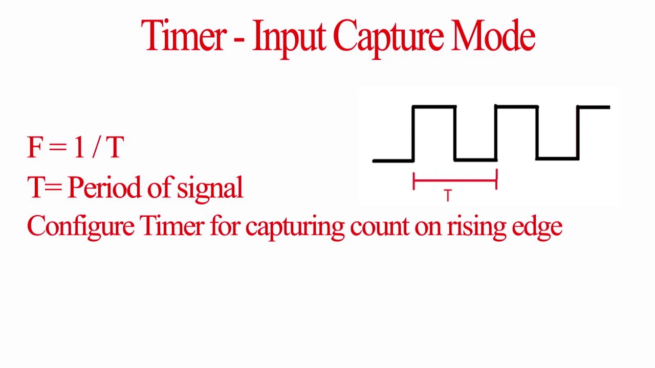
Utilizing the Timer1 Input Capture Unit to measure external signal frequency, period, and duty cycle with high precision.
Integrating timer-based interrupts with low-power sleep modes to design energy-efficient embedded systems.
Managing multiple timer interrupts concurrently and handling critical sections of code (such as atomic operations and volatile variables).
240.2K views4.3Klikes17:22Original Release: 2018-02-19
[background music] Welcome back to Leveling Up Your Arduino Code, or leveling it down, however you want to see it. This time, we’re going to talk about timer interrupts.
If you’re not familiar with writing directly to registers or how interrupts work in general, I recommend watching the previous two episodes.
Microcontroller timers are like kitchen timers. They continue to count while you’re off doing other things, like prepping a salad or explaining how interrupts work. When they go off, you need to stop what you’re doing and go get that casserole out of the oven before it burns. Excuse me.
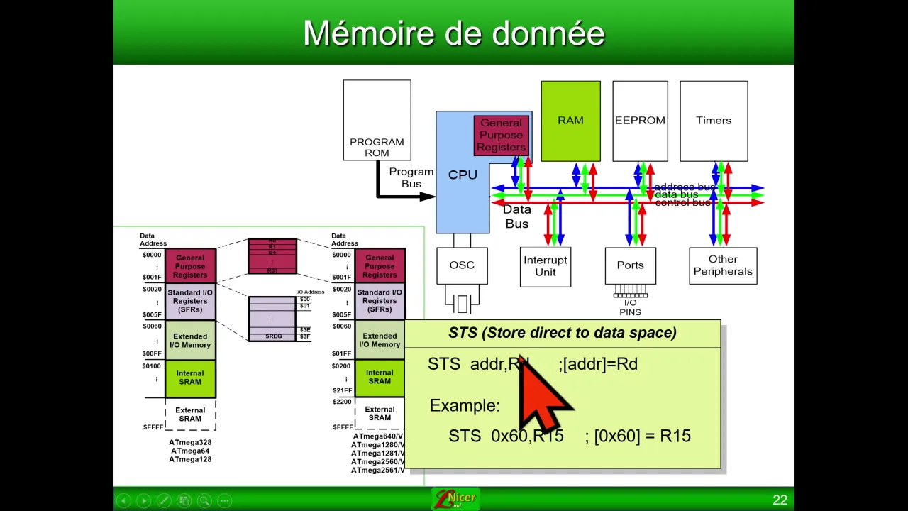
If we look at the various interrupt vectors available to us in the ATmega328P, we see that there are three different timers labeled Timer0, Timer1, and Timer2.
Scroll down to the register map and we see that each timer lives in memory as a special function register.
Timer0 is TCNT0, which stands for Timer/Counter0.
Timer1 is TCNT1, and notice that it takes up 2 bytes in memory.
Finally, Timer2 is TCNT2.
How timers increment automatically Let’s see how these timers get automatically incremented without any code.
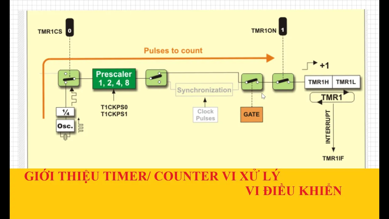
Each of these three timers can be directly or indirectly connected to the system clock. This system clock is a square wave that is produced internally in the microcontroller based on your settings. It could be generated inside the microcontroller itself, or from a connected oscillator or crystal.
The system clock is vital to the operation of almost everything in the microcontroller. The Arduino Uno, for example, has a 16 MHz crystal connected to the microcontroller. The ATmega328P generates a 16 MHz square wave from this, which is used to feed many functions, including our timers.
The timers can be connected directly to the system clock, which means the value in the timer register increments once every 62.5 nanoseconds, which we get by dividing 1 by 16 MHz.
The system clock is also fed into another piece of hardware known as a prescaler. The prescaler divides the clock by producing a pulse every 8 system clock cycles, or every 16 clock cycles, or however we define the prescaler.
Let’s say we don’t have a prescaler set. Every time the system clock pulse occurs, each of our timers increments by one. We’ll be focusing on Timer1 in this example.
Now let’s say we set the prescaler to 8. Timer1 increments only once every 8 system clock pulses.
As you can see, we can adjust these prescaler values to change how fast each timer counts.
Timer sizes and rollover Now the question is: what do we do with these counting timers?
Timer0 and Timer2 are both 8-bit timers, which means they count from 0 to 255. Note that once a timer reaches its maximum value, it starts over again from 0.
Timer1 takes up two registers in memory, so it’s actually 16-bit. That means it can count from 0 to 65,535 before rolling over.
How timers generate interrupts Each timer can generate one or more interrupts.
We can write a value in another register so that when one of the timers equals that value, it throws an interrupt. This is known as a compare match interrupt, and all of the timers can generate these interrupts.
Similarly, we can tell the processor to generate an interrupt when one of the timers overflows, meaning it rolls over from its max value back to 0.
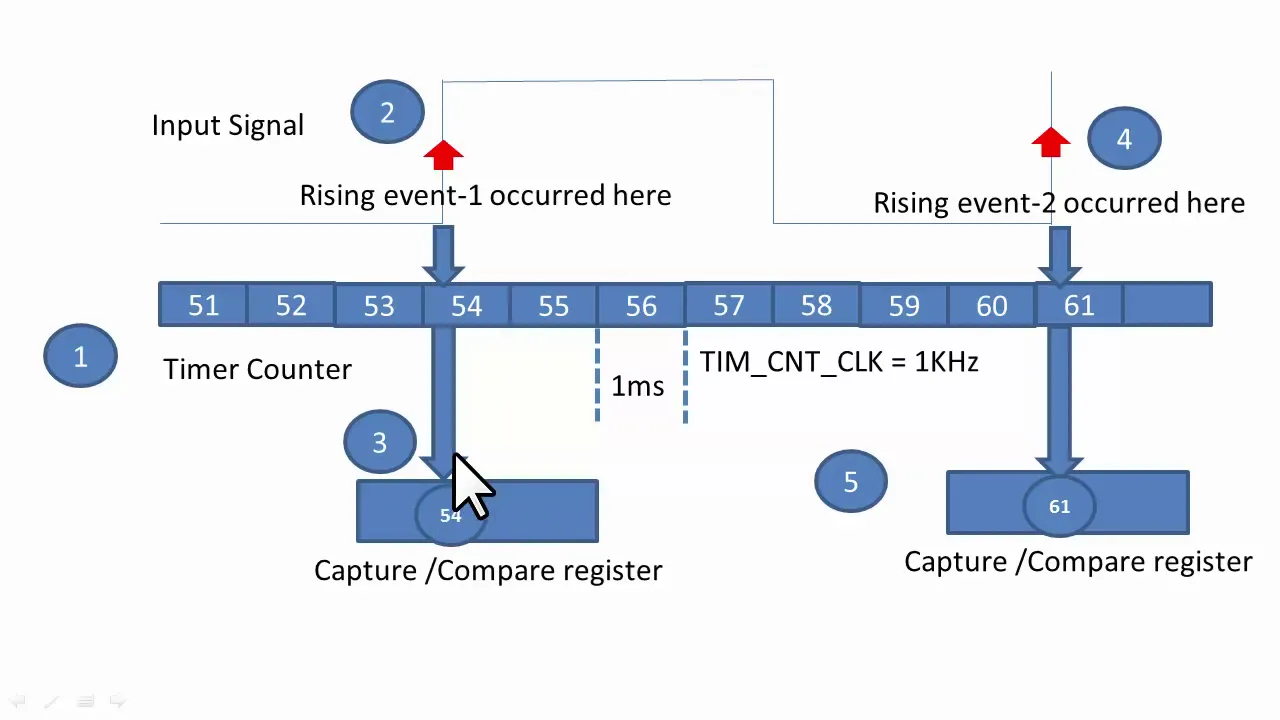
Finally, Timer1 can be configured to store its current count to another register whenever an external event happens on a pin. This is known as input capture.
If you are working in Arduino, note that several functions rely on timers to operate.
So if you begin playing with Timer0, the delay(), millis(), and micros() functions will no longer work properly. The same applies to the Servo and tone() functions for Timer1 and Timer2.
The analogWrite() function uses all three timers on the Uno, but which timer depends on which pin you’re using. For example, if you want to manually control Timer1 for other things, you probably shouldn’t use analogWrite() on pins 9 and 10.
Timer1 interrupt examples Let’s see how these different interrupts might be generated using Timer1 as an example.
As we run our program and time progresses, we’ll see the value in Timer1 continually increasing at each system clock pulse, or at a pulse from the prescaler.
One thing that happens is each time Timer1 is incremented, its value is compared to the value in the output compare registers. For example, we might have 30,125 stored in the OCR1A register. When Timer1 equals that number, a compare match interrupt is generated. In this case, the interrupt source would be Timer1 Compare Match A.
Next, every time the Timer1 counter rolls over from its max value to 0, an overflow interrupt is generated, known as the Timer1 overflow source.
Finally, if we have input capture set up for Timer1, whenever a logic level change occurs on a specific pin, such as the ICP1 pin (Port B, Pin 0), an input capture interrupt is generated. At the same time, the value of the Timer1 counter is stored in the ICR1 register, so you can refer to it later to see exactly when that event occurred.
Compare and overflow interrupts are useful if you want to toggle a pin or read from a sensor at precise, regular intervals. Capture interrupts are great if you need to measure the time between pulses or measure the frequency of an unknown signal.
Example: Blinky using Timer1 compare match To see how to set up timer interrupts, let’s look at an example: the classic “blinky” program.
You will need an Arduino with an ATmega328P, such as the Uno or RedBoard. We’ll be using pin 13 this time, since it’s already connected to an onboard LED. Notice that Arduino pin 13 is actually Port B, Pin 5 on the ATmega328P.
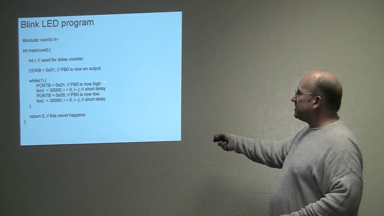
We’ll start with this simple example: set pin 13 as an output, set it HIGH, wait 500 milliseconds, set it LOW, and wait another 500 milliseconds. If we run this, it blinks the LED at a 1 Hz rate.
First, let’s change this to use direct register writes. Instead of pin 13, we’ll use PB5. This is defined by the AVR libraries. PB5 refers to bit 5, so we can use it when dealing with the data direction and port registers.
Delete pinMode() and change it to: DDRB |= (1 << LED_PIN); Notice we’re using DDRB here, because we’re using Port B instead of Port D.
Delete everything in loop() and write: PORTB ^= (1 << LED_PIN); delay(500); This flips bit 5 in the PORTB register, which turns the LED on or off. The processor then does nothing for 0.5 seconds before flipping the bit again. Run this again and you’ll see the LED blinks the same way.
Now, take a look at your ATmega328P datasheet. We’ll use Timer1, since it can count the highest and it’s not used by delay(), millis(), or micros() in Arduino.
Go to the register description section under Timer/Counter1.
We don’t need the TCCR1A register for what we’re doing, but we do need to reset all of its bit values to 0, since Arduino often sets these by default for analogWrite().
Scroll down and take a look at TCCR1B. We don’t need input capture or waveform generation mode bits right now, but we do need to set the prescaler.
What we’ll do is set the Timer1 counter to 0 and let it count up. We’ll also set the output compare register OCR1A to a value less than the Timer1 max value of 65,535. When Timer1 reaches that value, a compare match A interrupt is generated and will execute our interrupt service routine.
In the ISR, we will toggle our LED. Timer1 will continue counting, and when it reaches the compare value again, another interrupt will trigger. Repeat forever to get a blinking LED.
Finding the compare value for 500 ms Ideally, we want the time between compare interrupts to be 500 milliseconds, so we need to find what value to load into OCR1A.
We know the clock period with no prescaler is: 1 / 16 MHz = 62.5 ns We want 0.5 seconds. With no prescaler: 0.5 s / 62.5 ns = 8,000,000 counts That won’t fit in a 16-bit counter.
Try a prescaler of 8: 0.5 s × 16 MHz / 8 = 1,000,000 counts (still too big) Try 64: 0.5 s × 16 MHz / 64 = 125,000 counts (still too big) Try 256: 0.5 s × 16 MHz / 256 = 31,250 counts (fits) Try 1024: 0.5 s × 16 MHz / 1024 = 7,812.5 counts (not a whole number, so the timing would be slightly off) So we’ll use a prescaler of 256 and load 31,250 into OCR1A.
That means we need to set the CS12, CS11, and CS10 bits to 100 to select a prescaler of 256.
Code setup In code, create constant variables: const uint16_t t1Load = 0; const uint16_t t1Comp = 31250; In setup(), after we set our LED pin as output: Write TCCR1A = 0; to reset Timer1 Control Register A.
Set the prescaler bits in TCCR1B for 256 (CS12 = 1, CS11 = 0, CS10 = 0).
Write TCNT1 = t1Load; to load the timer with 0.
Write OCR1A = t1Comp; to set the compare match value.
Write TIMSK1 = (1 << OCIE1A); to enable the Timer1 Compare Match A interrupt.
Write sei(); to enable global interrupts.
Delete the PORTB bit flip in loop(), leaving the delay(500); to pretend the processor is doing something important.
Under loop(), add an ISR for the Timer1 compare match A vector: ISR(TIMER1_COMPA_vect) { TCNT1 = t1Load; PORTB ^= (1 << LED_PIN); } Upload this code. Not surprisingly, the LED continues to blink at the same rate.
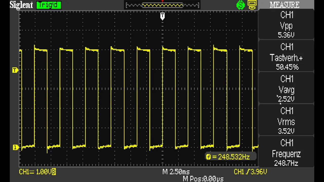
Just to show that we really are blinking at 1 Hz, I’ve set up this oscilloscope. As you can see, it’s about 1 second measured from one rising edge to the next.
Timer interrupts are great for running pieces of code at exact intervals.
Using CTC mode for efficiency We can make this slightly more efficient by using Clear Timer on Compare (CTC) mode. This tells the hardware to automatically reset the timer back to 0 whenever a compare match occurs.
Go back to the datasheet and look at the waveform generation mode table. We want mode 4. In this mode, the timer resets to 0 whenever it reaches “top,” and “top” is whatever value is in OCR1A.
To use this mode, we need to set WGM12 to 1. Interestingly, WGM12 is in the TCCR1B register.
In our code, just before we set the prescaler: Clear WGM13 Set WGM12 Then, in our ISR, delete the line where we reset TCNT1.
Run this code, and sure enough, we’re still blinking at a 1 Hz rate. Using CTC mode only saves you one instruction, but when you need to make your ISRs as short as possible, every instruction counts.
There are many more ways to use interrupts that we didn’t cover here, like input capture or overflow.
If you want to see more videos like this, make sure you subscribe to our channel. Good luck, and happy hacking.
[outtakes] We can make… We can make… and we connect this… No, that was… similarly… don’t make this word bother me again.
Since between two points, and when two trains connect in Cincinnati, how fast are they going.
Awkward pause. Thumb, thumb… is that a real word.
That wasn’t right, by the way. No, one second measured from…
Up Next

6:15
Harmonic Animation: Understanding Synthesizer Harmonics
@ozhalljr
743 views•2022-01-04

12:54
Triumph of Orthodoxy Icon: Byzantine Art & History Explained
@BenCallan
2.1K views•2024-08-06

4:48
Infrared Sensor Basics: Arduino Object Detection Tutorial
@sparkfun
78.1K views•2013-02-20

1:42
Game of Thrones Opening Credits: A Cinematic Analysis
@gameofthrones
46.3M views•2011-04-18
Related Study Plans & Knowledge Roadmaps
Structured learning paths in General & Interdisciplinary Studies
general-studies
Elevator Engineering: History, Physics & Cities
01From Hoists to Safety Brakes: The Dawn of Vertical Lift
02Hydraulic vs. Traction: The Engineering Physics of Elevators
03Modern Speed, Safety, and Algorithms
+ 2 more learning modules
12h5 modules
Explore Roadmap
general-studies
Rubber: Material Science, History & Geopolitics
01Origins of Natural Rubber & Mesoamerican History
02The Chemistry of Natural Rubber & Vulcanization
03The Geopolitics of the Rubber Boom & Colonization
+ 2 more learning modules
12h5 modules
Explore Roadmap
general-studies
Containerization: Evolution, Logistics & Trade
01Ancient Trade & Bulk Cargo: Amphorae to Barrels
02The Industrial Revolution & Cardboard Packaging
03The Containerization Revolution: Malcom McLean
+ 2 more learning modules
12h5 modules
Explore Roadmap
general-studies
Textile Tech: Evolution, Labor & Global Impact
01Pre-Industrial Textiles: Handloom & Cottage Industry
02Mechanization: The Spinning Jenny to the Power Loom
03The Factory System & Global Labor Transformation
+ 2 more learning modules
10h5 modules
Explore Roadmap