






















Infrared sensors work by emitting infrared light (at specific wavelengths like 940nm) and detecting reflected or transmitted light to sense objects; they require matching emitter-detector pairs, can be tested using a cell phone camera to visualize infrared light, and when connected to an Arduino's analog input, provide distance measurements that enable applications like robot object avoidance and wall detection.
Infrared Sensor Basics: Arduino Object Detection Tutorial
Added:Basic concepts of electrical circuits, including voltage, current, resistance, and Ohm's Law.
Fundamentals of the electromagnetic spectrum, specifically the characteristics and properties of Infrared (IR) light.
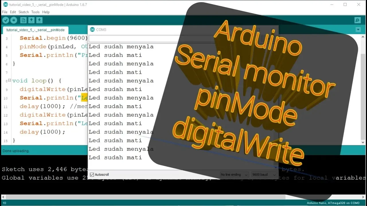
Elementary Arduino programming, including writing basic sketches, configuring digital/analog input-output pins, and utilizing the Serial Monitor.
An understanding of basic optoelectronic components, particularly Light Emitting Diodes (LEDs) and photodiodes or phototransistors.
Implementing sensor calibration techniques to handle noise and ambient light interference in varying environments.
Integrating IR sensors into robotics applications, such as autonomous obstacle-avoidance and line-following algorithms.
Exploring advanced distance-sensing technologies, such as Ultrasonic sensors, LiDAR, and Time-of-Flight (ToF) sensors for sensor fusion.
Studying IR-based communication systems, including modulation, demodulation, and remote control protocols like the NEC protocol.
78.1K views230likes4:48Original Release: 2013-02-20
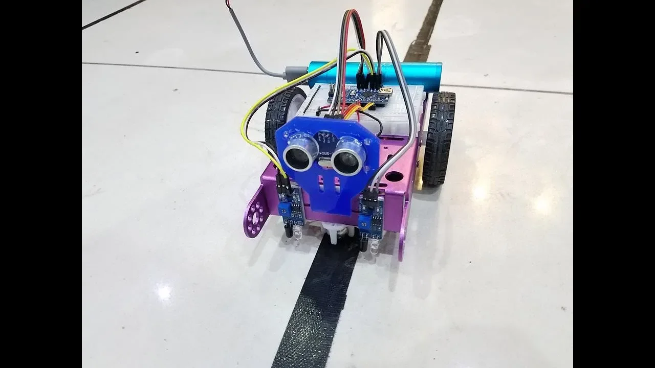
welcome back to our series on continuing tools for robotics I'm Jeff with spark fun Electronics today what we're going to talk about is infrared we're going to go through some of the most basic infrared Sensors how to set them up and uh look at a little example stuff on troubleshooting how to figure out whether you're actually getting signals out of them and at the very end of the video we'll hook them up to an Arduino and do some serial read uh to give you guys some sensor tools for robotics so I'm using the most common infed LED emitter pair that we offer in our catalog 940 nanm that's the wavelength of light that the emitter emits and the detector is tuned to that on this uh one of the things as you move into more complicated stuff with infrared is some infrared has a carrier frequency we're not going to talk too much about that today but be aware that if you're mixing and matching infrared that they come in different frequencies um today we're using the match pair so that shouldn't be a problem if I look at the emitter it should have a yellow dot on the top and then my detector has a red dot and that's how I can tell which one is which when I pull them out of the bag CU they're tiny and they look almost exactly the same so let's talk a little bit about the emitter what I've done is set up a simple circuit here on this small breadboard with the emitter and I want to make sure it's working I'm going to troubleshoot each part of this puzzle one at a time um just to give people some tools for how to look at this without fancy equipment and then later on we'll put it on the scope and look at it on the scope cuz that's kind of nice too too so the first thing I've done is like any LED in this circuit we have a long leg and a short lag and the long leg goes to positive I've got a 330 ohm current limiting resistor in this and I've got uh four ablea batteries in a battery pack just powering this and and you'll see why we're doing this on separate breadboards in just a little bit but I want to make sure that I'm actually getting infrared light out of this and I can't see infrared it's outside the visible spectrum one of the ways I can do this is take my handy dandy cell phone camera and I can look through my cell phone camera and I can actually see the purple light through the polarized filter on the cell phone camera now we took Greg's really fancy camera and we looked at it and we couldn't see the infrared light until we actually held a pair of polarized sunglasses up against the regular camera so if you had a regular camera you could hold a pair of polarized sunglasses in front of it and you should be able to see that purple light this is the schematic for the emitter there's also one on the product page at Spark fund.com let's move on to the detector I've set up my detector circuit and what I've done is built a really standard voltage divider if you look at my drawing right here I've got my Supply voltage and here it's nominal about 5 volts we got some old weak batteries it could have been six and I would have put a little larger resistor in there but we've got Supply voltage I've got a 10K resistor and then my detector and I'm going to read right in the middle the other way to approach that is with an LED what I'm going to do is actually plug my LED in across the detector leg matching my detector and you can see it's on the interesting part of this is is as I move my emitter in close the LED goes off and as I move it away it comes on so this is normally high and then in the presence of that 940 nanom Spectrum it goes low as a more tangible way to see what's going on with the infrared detector I've hooked up the oscilloscope and we can watch as it drops an analog voltage value as I move closer and closer and closer and when I get right up on there I'm almost zero the nice thing is is that we have an analog input on Arduino and we can read that analog voltage as a distance so what I've done is I've changed the orientation of my emitter and my detector so that they're now instead of facing each other they're now facing the same direction and if I use something that's reflective I can get reflected light back and this is great for robotics I've also hooked up that detector to the analog read port in Arduino so I can look at my screen and as I move my reflective object in I can see the change in my numbers on my reflective screen and I can write a piece of code that goes with that so I can say if that value drops to below a certain amount I'm probably up against a wall and I can turn off the motor on that side and let the robot crab away from that wall so it's a really great object detection scheme there's a bunch of links on the product page which described object detection Um this can also be used for quadrature encoder if you use a little disc with black and white areas on it as something moves around in a circle you'll get different values back from the reflected value so that's kind of the skinny on IR detectors and emitters and we hope that you can join us on the next [Music] one
Up Next
12:09
Webots Supervisor API: Robot Position Tracking and Control
@coolrobotics
5.1K views•2020-09-04

12:54
Triumph of Orthodoxy Icon: Byzantine Art & History Explained
@BenCallan
2.1K views•2024-08-06
17:22
Arduino Timer Interrupts: Advanced ATmega328P Register-Level Programming
@sparkfun
240.2K views•2018-02-19

1:42
Game of Thrones Opening Credits: A Cinematic Analysis
@gameofthrones
46.3M views•2011-04-18
Related Study Plans & Knowledge Roadmaps
Structured learning paths in General & Interdisciplinary Studies
general-studies
Elevator Engineering: History, Physics & Cities
01From Hoists to Safety Brakes: The Dawn of Vertical Lift
02Hydraulic vs. Traction: The Engineering Physics of Elevators
03Modern Speed, Safety, and Algorithms
+ 2 more learning modules
12h5 modules
Explore Roadmap
general-studies
Rubber: Material Science, History & Geopolitics
01Origins of Natural Rubber & Mesoamerican History
02The Chemistry of Natural Rubber & Vulcanization
03The Geopolitics of the Rubber Boom & Colonization
+ 2 more learning modules
12h5 modules
Explore Roadmap
general-studies
Containerization: Evolution, Logistics & Trade
01Ancient Trade & Bulk Cargo: Amphorae to Barrels
02The Industrial Revolution & Cardboard Packaging
03The Containerization Revolution: Malcom McLean
+ 2 more learning modules
12h5 modules
Explore Roadmap
general-studies
Textile Tech: Evolution, Labor & Global Impact
01Pre-Industrial Textiles: Handloom & Cottage Industry
02Mechanization: The Spinning Jenny to the Power Loom
03The Factory System & Global Labor Transformation
+ 2 more learning modules
10h5 modules
Explore Roadmap