



![[2.1] Real Mode Memory Addressing in 8086 Microprocessors](https://i.ytimg.com/vi/8ekLJuhbNLg/maxresdefault.jpg)


![COA [Module 01 - Lecture 06]: Execution of Program and Programming Languages](https://i.ytimg.com/vi_webp/WgTAUZ58jEY/maxresdefault.webp)





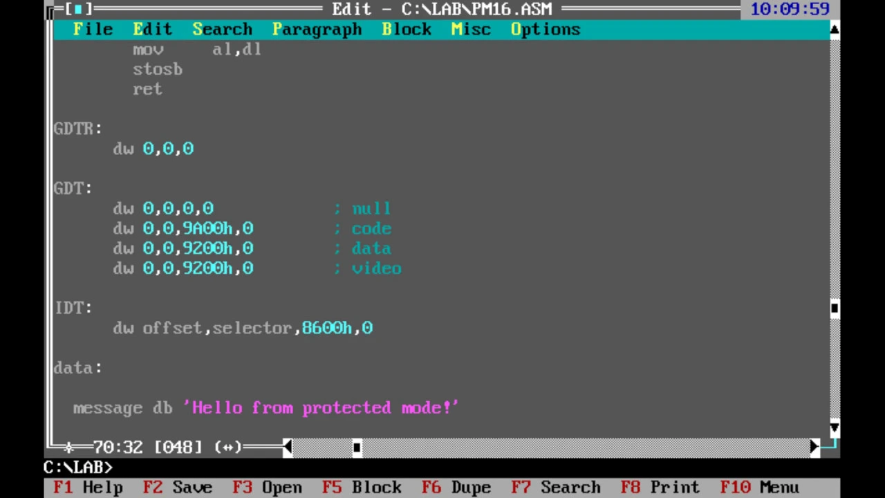













The Global Descriptor Table (GDT) is a critical data structure in x86 protected mode that contains segment descriptors defining memory segments with their base addresses, limits, access permissions, and flags. To enter protected mode, developers must first enable the A20 line using Fast A20 (reading from I/O port 0x92, OR'ing with 2, and writing back), then construct a GDT containing a null descriptor followed by code and data segment descriptors specifying the base address (32-bit), limit address (20-bit), access permissions (including DPL for privilege levels), and flags (granularity and size bits). The GDT is loaded using the LGDT instruction, interrupts are disabled with CLI, and protected mode is enabled by setting the PE bit in CR0. Finally, a far jump to the 32-bit code segment initiates execution in protected mode.
OS Development: Configuring the Global Descriptor Table Explained
Added:hello and welcome to uh the fourth lecture of my operating system development lecture series um today I'll be talking about going into protected mode um and uh for that I will be talking about how to set up a global descriptive table I'll be talking about the a20 line and then I'll actually talk about how to get to protect to the protective mode um so so let's begin first I would like to address a little pun um the a20 line uh which is the sort of relic of of the past so as I have previously mentioned um in real mode um there there is um a usage of the 20 bit addressing system right so we have the segment we have the offset so uh back in the days when you just had 16bit x86 CPUs um they would all have um or at least a majority would have a 20 bit um address bus so um because of that right all of the different programs and their memory allocation and everything it was made with a 20 bit address buzz in mind um so then eventually uh people have started making 32bit CPUs right uh but porting software was very difficult um now not only did people have to change the construction structure and such uh to match new 32-bit CPUs one problem was that people were considering a 32bit address bus right it seemed like a quite logical step when creating a 32bit CPU um however that was quite problematic because um that would just add an extra step of complexity if it comes to porting 16 bit software that because this old software was designed for taking advantage of the 20 bit bus and um it was only designed for dealing with this address space then if you tried to implement um things that um would use higher addressing um you know the other algorithms which did not predict that um would not deal with that and would therefore have to be changed um to prevent this they invented a sort of um you could even call it lazy solution because many people do like to critique it um it is called the a20 line um so a um in a20 uh stands for uh address right so it's the address line 20 um so basically what we said is okay um we will literally restrict the amount of the address bus that can be used to 20 bits so this is a solution and it's it was a relatively good solution at the time because programs did not require that much memory and was just easier to Port 16bit software so it was a relatively good solution uh but it has um um Okay so it is a some sort of solution to to to this problem and so you would have this feature of the a20 line which would allow you to go further right um I'm not sure if I phrased that correctly so you had a restriction to 20 bits of the address bus by default all programs would only be able to access 20 bits of the address bus if someone for some reason you know if they needed more memory if they needed something more Advance they needed 32bit addressing they could enable the a20 line and thus have access to the rest of the bits of the address bus the the rest of the lines the the lanes and and what whatever you want to call them channels even right so that's the idea of the 820 line and um then when new processors were made you know we were like okay you know um since this was like disabled by default you know let's for compatibility purposes and stuff you know let's just keep it disabled by default and um basically for this very long time you know it was just like okay okay backwards comp ability and it eventually became the standard and it is normal right now that pretty much every x86 processor has a the a20 line disabled by default so this is a sort of relic of the past sort of annoying even where um we have to enable the a20 line to be able to actually address more than 20 bets um or we can use more than 20 bits to address I think that's a that's a better way to to word it so um sadly this didn't evolve into into new processors that that it should be enabled but what has evolved is the way that uh the a20 line can be enabled so what is very convenient highly convenient to um programmers nowadays is that there is a feature on most uh CPUs that is called fast a20 and Fast 820 is um a feature that so it it you could even just call it a bit because basically what CPU manufacturers have done is they've simplified the whole Act of enabling the a20 line to flipping a single bit so um this this feature it's called Fast a 20 right you simply have to uh read from a port the port number in hexad decimal is 92 so you have to read from that Port you have to flip V a20 bit and then right to that Port that's it and this is supported by most x86 CPUs nowadays this is fast a20 um it's this extremely simple way to turn on the a20 line to enable it you you can simply set this bit to one um so in order to read from this port right you would use um an x86 instruction just such a obviously this is an IO Port by the way you have to communicate through the cpu's io bus so what you're going to do is just um in and uh by the way this is an 8bit value that you're going to read this is an 8bit value that is stored in the sport so we're just going to use an 8 bit register like the lower a register you could use any any other 8bit register that is to your liking and you simply um get the value from this ports using the I obus um then um you have to flip the bit and the bit that is responsible for this is the second youngest bit so the second youngest bit so if we think about representing it as a bind right um we have some values um six we have six bits then we want a one no matter what and then um we don't really care so how can we ensure with a logical operation that we will end up um with a value of this form well we could simply perform an or operation right which can flip this uh the second youngest um bit to a one right so we can simply store the value 0000000000 1 0 and then when you or the value that you read from this port with this bite you can be entirely sure that the result will have the one in this place and this means that the fast a20 bit is going to be one and hence the a20 line is going to be enabled as long as fast a20 is obviously supported um so um we can actually um simplify this a little bit in our code from a practical perspective by noticing that this value is simply a a bite for the number two in decimal um so we can or um our value of Al with the number two and this will flip the fast a20 bit now uh you might be thinking to yourself if if you're already sort of experienced with um flipping bits from uh different registers and such from different PS um you might be asking yourself well why don't we use the or right why don't we use an exclusive or because an exclusive or is actually what flips a bit um right because when you have um some value right and uh you you SAR it with one right then if you have some value right you have some value if you and you you you have some value exort with one then if it was one then you're going to get zero so you flipped the one to a zero if it was a zero then it's going to end up being a one in form of exor so an exor operation is what really um does this also we can't use not because not takes a single parameter I would just like to um mention that um yeah so why don't we use the exclusive orgate and the answer is simple because we don't actually want to flip the B that is because on some CPUs that is that is very rare but it can happen they can support fast a20 and the a20 line can be enabled by default this is very rare but for compatibility purposes it's good not to flip this but just ensure that this bit is going to be equal to one because this is our goal our goal is to make this bit one to to make sure that fast a20 is enabled we don't want to flip it we will usually flip it because the bit will be zero because the a20 line is usually disabled but it can be the case that um that it is enabled and that's in that case we don't want to flip it to a zero we want to keep it as a one and in this case the orgate when is going to take a one and a one it's still going to return a one unlike an exclusive Pate which is why we use this or operation over here then we want to write uh Tu this ports which we do for the CPU IUS again so we simply perform an out to the ports with our new value that we perform those operations on uh which in my little example was toward the lower a register again you could have used the higher a register you could have used the lower B register it doesn't matter we're just trying to uh store this AIT value from this uh Hardware Port and we simply out um our register that we performed this or operation on back to this port and just like that um you you've enabled the the a20 line on most um CPUs um and this is very useful because now when we will go into 32bit protected mode um we will be able to address more than just 20 bits so we will be in a 32bit CPU mode and we'll actually be able to use 32bit addressing so um that is a very important consideration um that one should probably execute at any point before going into protective mode so I just wanted to mention this a20 line right so um now um the slightly more difficult part is um the global descriptor table so the global descriptor table is a pretty valuable lesson um because um it sort of teaches you how to follow a format and just give values to a format and then loaded by some means so this is a simple very simple exercise uh that can always help but what even is the global descriptor table what is it for um so the global descriptor table or V gdt um as the name suggests it's a table so it is a collection of different values um now this table is global which means that this T table will be accessible to us anywhere in our uh in our operating system then you you have the descriptor part and a descriptor um as one might guess is something that describes something so we have a table of descriptors which are values that describe something to be precise This Global descriptor table contains information about different segments in memory so we have those different segments and we need to say uh we need to specify things like okay uh what is the base address so at what point can you find that the earliest what is the limit address so beyond which point can you not find that thing how can you access that thing how should that thing be address so on um and this is actually a very vital component the the very idea of protected mode because the protected mode as the name suggests is just a protected mode of the CPU many people mistakingly think of it as the 32bit CPU mode in x86 this isn't the entire uh picture and that is because um when you dealing with um 32-bit code it might not be protected because you could have as well be in something like unreal mode that exists perhaps it's not that common but it exists and there's also 16bit protected mode which is a protected mode as it offers protection features but it is not 32 bit it is 16 bit so I would just like to point that out the name protected mode is there for a reason it actually protects something and the global descriptor table is a pretty vital part of it because um it is one of um it can it can be used for triggering something called the gpf so a gpf it's short for a general protection fault and those are faults um which are caused when for example some memory is not access in the way that it should be or some code that shouldn't be executed is executed so this is a vital protection feature this General protection fault and um the way that a CPU usually uh manages gpf so well and triggers them is through the global descriptor table and this will for example allow you uh to later even when when you're making user space applications you'll get General protection faults when you will try to do things that are not allowed so um I be talking a bit more about that later in this lecture but um when when these user space programs do things that shouldn't be done by user space programs it will also trigger a gpf um so the global descriptor table is really an important component of of protective mode and it is required uh for going into protective mode right so what are the actual parts of uh of gdt and I'm going to be completely honest here I'm I don't remember everything about the gdt um because I usually just look at a CPU manual I remember most of it I might even remember all of it it might just have I it might have just happened but I do remember all of it but um just in case um I literally have um a piece of paper right next to me that I might take a look at um if I ever forget uh something about the gdt during this lecture um so people don't usually memorize for the whole gdt um anyway what is um Global descriptor table comprised of well usually there's first something called the null descriptor then you'll have your code and data descriptors then you have the um G DTR which is the global descriptor table register and um I should have actually written this here uh but let's just say yeah just actually erase that so you can have a task State segment descriptor this is TSS for short and then you have your gdr um okay so what are those so if it comes to the null descriptor it is literally eight bytes of just zeros it's 64 bits of zeros placed next to each other so this might seem a little strange but it's actually very important because it allows you to it allows well CPU to nullify Des scriptures when it is necessary and to properly deal with the gpfs that I previously talked about so for the programmer um not really an issue uh but it's pretty important for the CPU then you have the code and data descriptors um so a code descriptor it I think it's uh pretty um self-explanatory it is um it's eight points that describe um the details that I previously talked about segments like the Base address the limit address I'm going to write that down as well soon and specify all of that about the code the actual executable data uh well I shouldn't say say data the executable ones and zeros um so as you might know code and data are not really you can't really differentiate between them on a low level because code is a sequence of ones and zeros you know it corresponds to op codes to operands uh that your CPU can fetch uh then uh decode and execute um but and generally you know data is also just ones and zeros except it can represent some value or it can represent the type of something right so fundamentally they're the same thing we as humans see them as something different and um in order to sort of um formalize this distinction a bit more and for the um CPU to know um what is code with data how to differentiate between them you have to load a gdt with code and data um descriptors so that's what they're for um and yeah the the scriptures themselves they allow you to uh say for example how the data should be accessed how the code can be accessed um I'm going to go into details uh later so those are the code and data descriptors then you have the task State segment descriptors now those are um actually optional those are optional and um and task State segment it is usually used when you actually um when you make user space multitask in so um I'm going to be talking about multitasking in a in a lecture but will come uh probably in like half a year or something considering my Tempo I'll try to speed it up a little bit don't worry about um um to give you the bare idea of multitasking right um you start executing a task and then uh when you want to execute another task right because uh multitasking right a CPU can only execute one instruction at a time um so a common misconception is that when you run multiple programs on your computer all of them are actually running simultaneously as in your CPU is doing an instruction for your browser for your um video game for your instant messenger program whatever um this isn't actually the case um because yes there is multicore right which is you know having multiple CPUs really and them having execute instructions independent of each other and use symmetric multiprocessing S&P and stuff right um but the essential idea right and the way that multitasking machines existed on single core CPUs is because they have something called a scheduler which wisely gives um CPU time to different processes so you have some process running right and let's say it's your browser ADV then you also have some video game and they're supposedly running simultaneously but what actually happens is it starts executing browser code and then when the Schuler decides that um now the video game deserves some time if it comes to this time we we're talking nanocs so and when it starts executing the video game code you know it has to ensure that when it goes back to the browser it is in the same state that it was and for that you use a mechanism called context a context switch where uh basically what you do is you store something called a context which is basically the state of the process so you have um a bunch of browser code that executes and then once it's uh time to go to the video game code it does a preemption and it saves this state that um it saves the state that the browser was in which is called this context so it has this context stored in memory and then it starts executing the video game code and once it's done uh with the video game code it's it places the state of the video game into the memory again this is called a context and then and the reason this is called context switching is then when you want to execute browser code again it switches this context to what the browser had saved in memory so now it takes the browser's context and now the browser knows where it left off and it can execute um code from the point that it ended uh with all the register valys and such that that it had at this point um and then once it's done it loads the context for the video game and and then the video game can execute code from the states same state as it ended in um so this was um again you don't have to understand all of this because I'm going to go in depth and and in later video but um to explain what a task State segment is it's basically that context well this is a descriptor for them um for for a TSS but um every task in in at least in proper user space multitasking how it should be should have a different TSS the or a testate segment that describes this um the the the state of of a process or a context right so this the tssd or the test St ST segment descriptor those are optional because obviously when you're still uh running in um rank zero I will talk about that in this in this lecture but for now you know um we're running in not user space let's just put it like that for now um we obviously aren't forced to create test State segments because we're not going to create user space multitasking at the moment uh then you have the gdt so this is simply um a descriptor you could basically call it the descriptor it's a bunch of information about where the gdt starts and how long is the gdt that's pretty much the only two things that have specifies where's the gdt and how long it is it um so obviously where it starts that that it's pretty obvious we obviously want to know where our gdt begins um as for the size um it is also useful because the size of a gdt is not fixed um the reason for that is because for one you know you have optional Tas State segment descriptors so you know just because of that the gdt is going to vary in size generally if you'll want to implement user space you probably don't want to use the same code and data descriptors that you use for your kernel so you have to also create a user space code descriptor and a user space data descriptor um so the size of a gdt can vary okay so um now we have a general idea of how the gdt is built and um we can just ignore this for now and you will simply just place these three uh preferably just next to each other in memory actually I'm pretty sure it has to be next to each other I'm actually not sure I think the GD can be separated but these components and if you have TSS segments they have to be together uh because of the CPU instruction is going to read them like so um anyway but preferably just plays with GD and just right afterwards as well and um we're going to talk a little bit about the structures of those so the first is the null descriptor uh which I have pretty much entirely described and in fact I can write four characters or for me since this uh this whiteboard is as the name suggests white only I only have to write three characters but on a computer it's four characters um DQ zero I think this is a whole null descriptor so a null descriptor again it's just 64 zeros so this is literally the null descriptor this is literally the whole pieces of piece of assembly code that is a that is a null descriptor because it defines a q word which I'm pretty sure is 64 bits right uh because you have a word and double word yeah but so that's a quadruple word a key word so that's 64 bits this is your whole n descriptor from a practical perspective so well but it was easy let's now talk about the code and data descriptors our structure is very similar so I will just talk about a general segment descriptor and this is going to apply to both code and data so before we properly place it into the gdt format which I'm going to talk about uh let's first even uh list the parameters that we can set and ponder about uh to what value should we set those parameters um so the first thing that we have to specify is the Base address so this address is what is the earliest memory address that you can find this thing at um so it it will trigger gpf if it finds if it tries to access that thing as that thing uh before that address so for example if it tries to access a bunch of on zeros ask code where the code descriptor says the ver shouldn't be Cod so this is the Base address the earliest address then you have the limit address which dictates the maximum address for that thing so it's the opposite Bas address then you have to specify access permissions uh which I'm going to elaborate on and then you have to also specify Flags okay so um let's now think about what we can set all of these things to Let's let's first Think About The Base address well for our purposes we could just set the base also I should I should probably mention the Base address is stored as a 32bit value and the limit address is stored as a 20 bit value again this is a relic to the a20 line and the 20 bit address bus uh for real mode CPUs um um and and when I talk about Flags I will talk about um how to ensure that we are't limited to this 20 bit addressing when specifying the limit address uh but for now let's think about the base address um well for our purposes we can just set it to zero we could set it to the lowest possible address we don't really care we could just say that code can be anywhere data can be anywhere we can use our whole memory for anything we want um so this might be changed especially should be changed when you go to user space and you should dictate what what is going to belong as kernel code and user space code but for now we could literally say um we want this to be 32 zeros which I guess would be 0x00 no that that is uh so it has to be 8 hex decimal zeros I'm just going to write it in heximal so that's shorter and heximal zeros I think that's 32 bits um then you have to specify the limit address and again using the same logic let's just use our whole memory let's say code can be anywhere data can be anywhere so we since this is a 20 bit value right we can make this 0x f f f f f so the maximum 20 bit value uh written in hexadecimal of four Simplicity okay so now we have specified two of the parameters that we have to specify for a segment and our segment descriptor the base and the limit address now what about axis so the axis is um really just single bite where every bit or collection of bits actually it corresponds to some given axis parameter so the first one is uh the present bit um and the present bit uh it always has to be set to one because it dictates whether something is even a valid segment this could be set sometimes to zero as test and like segment test but generally you'll want this to be one because you obviously want your segment to even exist to be present so the present bit is going to be one uh then you have two bits to specify the DPL which stands for desired privilege level um so for Val I have to talk a bit about x86 ring protection um so I don't actually know how people do the diagram but I don't think I actually need the diagram um should I doagram whatever um let's do a diagram um so x86 offers something called ring protection or a ring system um the idea is that um you have those Rings which get smaller and they correspond to the amount of instructions that you can do or well not really just instructions or rather permissions that you have so what per what instructions can use and how you can use some instructions if it's risky um there are they're just a protection feature where you consider ring zero the most outer ring to have basically um well not unlimited but a lot of permissions the most that x86 gives you so ring zero is really this pure raw mode where you can pretty much do whatever you want you can communicate with an ATA driver and wipe out your whole hard drive if you want to um yeah so that's Ring zero ring zero is the maximum amount of permissions um and ring zero is also called the kernel ring and that is because um that is the ring that your kernel should run in that pretty much has to run in so ring zero is also called the kernel ring with with the maximum permissions um now I'd like to talk about um the very opposite ring three ring three is a ring with very minimal permissions it can do a very low amount of things and ring three is usually just called the user space and the reason for that is because user space code should be executed in ring three because the user should by Design have minimal permissions so in most operating systems your user space is going to be running in rank three as you don't want the user to actually have um the same amount of access to Hardware as your Cel does um there's also ring one and ring two and they're sort of in between they have some permissions that ring zero has uh but you know not to all of them U so ring one and ring two um they're usually used for drivers so ring one and two are usually the driver rings and that's is that is because you know a driver it often shouldn't have um kernel permissions right you um you think of drivers as those intermediate between Hardware that you use and the user that dictates how this device should be properly managed and you know they shouldn't just run as normal users space programs which is ring three they shouldn't have such minimal permissions they also probably shouldn't have colel permissions which is why ring one and two are usually used for drivers um ring one can also be used for system calls there various designs you can use them as you please but this is the the general structure and have for General use um sometimes ring one and two are not used um they're not used for drivers D drivers run uh in the kernel uh you can run drivers as kernel modules you can have a modular kernel um that is called a monolithic kernel right where you where you put everything into the kernel I talked about that in in the first video so usually when you have monolithic kernel so you put everything into the kernel or drivers and such um it's going to be all running in ring zero so that is the ring protection system and the Rings are also often more formally referenced as has privilege levels which makes sense because that's what they fundamentally are so this is our Desir priv desired privilege level and you'll actually see these um acronyms uh very often in in the OS St uh DPL stands for desired privilege level CPL that you will often see in De buug logs and such stands for current privilege level so okay some code was executed and what privilege level was it executed that's your CPL value and the designed privilege level is this fisal value of what do we want to uh what privileges do we want this to have so if it comes to the desired privilege level um you simply put the ring number in uh in binary right so ring zero would would be 0 0 ring one is 01 um Ring 2 is 1 Z and then ring three is 1 one um I hope that's that that really should be clear um so um if it comes to the DPL um I would just recommend setting this to z0 um because well we're currently writing a bootloader or at least I'm talking about the theory behind a Bo loader you obviously don't have to write it can use lemonade um and uh since you know this is a boot loader and we're doing a lot of Hardware stuff we should have Hardware permissions and then we're going to be loading a kernel the kernel as I said should run in ring zero and should have maximum permissions so the desired privilege level is going to be 0 0 then I think the next one is segment type but I'd just like to verify that um yes so this is a segment type or S uh and this bit simply um dictates whether this is a TSS or not so is this a TSS or is this a code or data descriptor um if it's a TSS then we set it to zero if it's a code or data descriptor um then we set it to one and since we're currently um not trying to make a TSS descriptor then um we will we will simply set this to one then the next bit is the um executable bit and the executable bit as the name suggests um tells us whether uh this segment is executable or not this is just a very cryptic way to say hey is this a code or data descriptor because obviously uh the only descriptors you have here except for the TSS descriptor is either code or data and code is executable data is not so this is pretty much the distinction between them and um V executable right it's going to be zero or one depending on whether you're currently making the code or data descriptor uh okay then we have uh a direct slash conforming bit um and yeah I think the this bit is first and letting have the read right I'm going to check that yes okay um so uh um this is the direction SL conforming bit so when you're in a data uh descriptor so if uh this is zero right so now the CPU knows that you're describing a data descriptor it's going to be the direction bit so this is going to uh simply State whatever you want to when you when you have data uh does it go uh from the from the Bas uh so does it go from bottom to top we just go from top to bottom if it comes to addressing um so you you could just set it to zero for the code segment which just means that it goes from bottom to top or you could have it the other way around with one it it really doesn't matter that much I mean it matters when when you look at your memory structure and such yeah um yeah and the the other bit is we conforming bit which um this is the one that you will have in code descriptors and it's the bit that dictates okay can this code that is placed in these B can it be executed in in the privilege levels that are below the DPL that is specified so this means that for example if uh we were making a user space code descriptor and we sent the DPL to 11 one which is ring three could this code also be executed in ring zero so this is the the conforming bit um in our example we don't really have to care you could set it to one you could set it to zero it really doesn't matter because if you set it to one then this the set of all privilege levels that are can executed in is 0 0 and then all the on that are below which don't exist so you can only execute it in ring zero and then if you set it not to one but if you set it to zero then it means that you can only execute in 0 0 but those are the same set so it really doesn't matter in our case so get set it to zero set it to one doesn't really matter for a code descriptor for a data descriptor it's your decision just remember it when you're going to be debugging then you have the readr bit so uh this again changes uh depending on uh whether you're making a code or data descriptor so for data descriptors um it's it's a writable bit which which which means okay can you write to this data um and sure why not I mean we often don't want our data to be read only so it's actually convenient and reasonable to set it to one um so yes sure we can write to to this data if you're making something very static and you wanted to secure it right with a GT could set it to zero to have just read only data read permissions are always enabled um if it comes to data descriptors because data wouldn't make sense if you couldn't couldn't even read it um then it's the readable bit if if it comes to a code descriptor so if you're making a code segment descriptor uh then the question is can you read from it because you can't write to it in no case uh are you allowed to write right to code um so this is always disabled but there's this question can you read it like you can obviously execute it as of a CPU can fetch thecode and execute um but you know you just have a bunch of instructions can you read them can you like take a look at the upod you know and you know this might be convenient at times it's not really that much of of an annoyance in in any case so why not let's set it to one if you want it to be zero set it to zero wouldn't it's not going to have much consequences for code descriptor um yeah so then we have our last bit which is um the AIS bit now this is pretty strange uh in pretty much any manual uh you will get told that this should be set to zero and on many forums uh like uh like hob and stuff you will see uh that people say that this should be set to one instead so uh what is the reason for this and which one should you pick should you chose the forums or the hardware manuals so um let's talk a little bit about what this bit even even repres s so basically um the CPU you know uh at first it it hasn't accessed any of those segments where defines access as you know interacting with that data registering that as successful uh yeah registering that as successful that's pretty much it and that it considers okay this segment can actually be properly accessed and when it is finally properly accessed what it does is it flips this bit to one and now the CPU knows that it shouldn't do any extra checks that it shouldn't bother with anything it can safely assume that this is accessible because it was accessed before so this will be changed to a one um so it actually doesn't matter very much because um you can set to zero and this is the quotequote proper way um to do so according to manuals um if you want to stick to those go ahead and set it to a zero uh the problem is is that it can be a little bit slower and the CPU will have to register accessing that sometimes it will falsely F that it hasn't access that you might encounter some problems so um for that reason many people simply set it to one uh so that the CPU can assume that it can safely access this with without any extra tracks so it knows that it was accessed before we're actually kind of fooling it that it was accessed before um and feel free to set it to a one you only really have to set this to a zero if you're debugging something if especially related to a gdt or GPS you know then you might want to to switch it to a zero but otherwise it can be a one but again it's your decision okay so those are the access bits we have a general idea of what we want to set them to you could literally copy this you could not you I mean you could copy this or you could decide that you know you want to change some bits entirely up to you um and 01 just remember depends on what you doing a coder of data description because be executable B okay so now um Flags so the first flag is granularity so this defines how the limit address should be treated and this is what I said about you know like ensuring that we're not limited to 20 bit and addressing um because if you were to set the granularity bit to zero it means that it would take the limit address uh like like it usually does in the sense that one address corresponds to one byte in memory so we can access this many bytes so this is zero and if you do that um then that's sort of inconvenient because you're going to be well you probably want to go with a 32-bit mode with this and you're not going to be able to use 32-bit addressing uh and again what have you enabled the a20 line for definitely not for this um so if you set this zero is going to take it as points if you set it the granularity bit to one it is going to interpret this um as the amount of pages and this is sort of hackish but not really because it's also semiofficial um way to extend this range to 32 bits um so it's going to interpret this as a standard page size such as for kib bints instead of uh instead of bints uh which will allow you to increase the the address range so this is granularity but highly recommend set it to one um then U the next bit is the size bit and it's actually a collection of two bits um no it's it's one bit yeah it's one bit so the size bit um simply dictates do you want to go into 16bit protector mode and 32bit protector or refer to to protective mode and this is what I talked about previously protective mode isn't just the 86 uh 32bit mode it is a protected mode that offers protection features and you could as well run it in a 16- bit mode uh if if you want to right so you can have 16 bit protected mode in which case uh you would set this to a zero and a zero means I want a 16bit protective mode but you probably want a 32bit protective mode it's probably the very reason you're trying to enable protective mode which is one the SI bit is going to be one then the next bit is the long mode bit long mode is the 64 bit mode of the CPU as I've probably mentioned in an earlier lecture and um currently this is not a gdt that we're going to use in Long mode um because we're trying to get into protective mode first before we go into long mode so the LM bit is going to be zero it would have to be one if this was strictly for lung mode and a little remark when the long mode is uh long mode bit is flipped to one the size bit would have to be zero a one here and a one here doesn't declare any legal mode then I'm sorry just to fill this format to have this nibble um we simply have a reserved bit that is always Z zero and always will be zero um and it doesn't represent anything it doesn't represent any parameter whatsoever it just be as a as a sort of padding okay great so now we have the A's bite 1 0 0 1 whatever 0 1 one again you can modify it however you want um then we have the flags which in this case is 1 one 0 0 probably going to be identical uh if you want to go into 32-bit protector mode again this is going to be different if you want to go into 16bit protective mode or if you want to be limited to a 20 bit uh address range I don't judge um so we have our Base address we have our limit address the access permissions and the flags so now we have every single value that one has to specify in a segment descriptor the only thing that is left is uh to actually place that in the proper format so the proper format for a gdt segment descriptor is to um first place 16 bit of the limit address so there a 16 bit then 24 bits of the Base address so this is um 24 bit uh then the axis B which is obviously eight bits um then the flags which are four bit then the limit address which is um for bit as well and uh then we specify um the last eight bits of the Base address so Base address which is um 8 bit so just like that in this format we have to place our 32bit Base address because 24 + 8 obviously makes 32 our 20 bit limit address um our 8 bit access points and our flags so uh we know what these things should be now we should simply place it in in our program and it should be fine and we will have a valid segment descriptor um yeah so if if you actually some those right this is two bints this is three bints this is one bint uh Flags in The Limited addess make one bite and this is one bite so that's 1 + 1 + 1 that's three + three that's 6 + 2 that is eight which means that um a segment the scriptor is is uh precisely 8 bytes and this is way we need that one reserved B uh so it wouldn't be seven bytes and the Seven bits because that would be strange okay so now let's uh talk about a couple practical remarks um we we have specified that dq0 is literally our whole n descriptor and um after that uh also you can make uh labels right so you could say like no descriptor no descriptor and like col and you know make those labels it's not necessary you don't have to do that but it's a design choice you you might consider so that it might be easier to deal deal with gdt later on but what you really need is a dq0 for a n descriptor then to make a segment descriptor and it doesn't matter you can make a code descriptor first you can make a data you could make a data descriptor first doesn't matter but you have to have both um and you're you're going to place it just right after the null descriptor so this is 16 bit so we're going to define a word and you're simply going to Define uh those 16 bits of limit address which is just going to be a bunch of FS you could write them heximal binary doesn't matter obviously the the number system is not going to matter uh there's no standard assembly instruction in most assemblers to to define the 24bit value so you'll most likely have to define a word and then a bite just a bunch of zeros right uh then for the access point you'll have to do a whole DB and uh you probably want to do it in binary so that you have like you know I don't remember it was like one one mean one Z 0 uh segment top so one if this was a code descriptor then this would be one and the data then would be zero let's say I would started with a code descriptor um un like um direct conforming so let's make that zero let's make that zero one whatever just a random Alum then you would put a b as in binary you could convert it to decimal or hexadecimal put it like that whatever um this plays into the format as a bite then since the flags and the limit address are both 4 bit you're going to probably um have to Define both in a single defined B uh instruction so um one way to do this would just be to say 1 1 0 0 and then the limit address is just going to be a bunch of ones 1 one one one b um that's one way to define this entire entire whole thing and then the Bas address which is just a DB and then uh you can just place a zero there for clarity you could place 0x 0 0 doesn't really matter it's up to you and uh yeah you simply Define the code descriptor like that just values defined next to each other memory after the no descriptor then you put the whole data descriptor it should be really simple um and congrats you've made the N descriptor the code and data descriptors so then you have to um do the GD so the GD is very simple because literally only specifies two things um I think the size is actually first I want it to do the opposite but so it's the size and the offsets let me just um yeah so Siz is first and then you have the offset um okay so size is a word which so it's 16 bit right and it's it's simply m the amount of um the amount of bytes except you subtract one and the size of your gdt um not including the gdt by the way and then the offset is a 32bit value yes 32bit at d word DD def double right 32 bits um memory address that um that the gdt is placed at so again really simple and the size yeah it's just the size of the gdt in byes uh except you subtract one and the reason you subtract one is because um it goes under this assumption but you're not going to give it an empty gdt because it would be very stupid to just give an empty gdt so it just assumes this cannot be the case so it Maps 0 to one so the inding thing of the size actually starts from a zero so if your gdt let's take an example the N descriptor as I've said 64 bits of zeros so it's going to be eight uh bytes then as we've said the code data descriptors both have eight byes each it's 8 + 8 + 8 uh that's just 24 and since indexing starts from zero and not from one because zero is mapped to one one is mapped to two and so on then to put the signs in the gttr you simply do Define word because it has to be 16 bit um and then you just uh put 23 if you have tsss if you have code and data descriptions for the user space and such you'll have to modify it accordingly then the offset we just do a DD and then you place the uh the address of your gdt so you might know the address of your gdt for example you might know that hey this is 7 e00 um because you might have put the gtt right after loading in more dis space so this some something you might have done and you might know this alternatively this is also considered better practice and to you know actually Define this n descriptor label where you do the dq0 before like the code descriptor label where you put the code descriptor and data descriptor right um and then you simply do DD uh n descriptor because um that way it's going to take this address because a label is nothing more than just a memory address of a given instruction that you that you pointed to um and you simply do that it's obviously going to give you the offset which is the starting address uh of the gdt reason the reason it's called the offset is obviously when you move three these bytes with uh and you index them you would have have to offset for example one or two by this address to get the address of that bik in the gdt um I think that makes sense so this is a GD very simple and this is the whole gdt um also theoretically the gttr is not a component of the gdt but come on they're like very very very strictly linked um okay so um now how can we actually Okay so we've placed a bunch of bites and words and everything in our program uh but those are just you know definitions and we're just placing zeros and ones into memory how does this actually work how can we make this gdt function well um the x86 CPU will literally do all of that for you so this is very convenient the only thing that you have to give it is the D referenc address of your gdt and it literally has an lgdt instruction which is load Global descriptor table not to be confused with LGBT um so this is the load Global load Global descriptor table instruction uh just place the D referenced GD address and it's going to uh load that for you um yeah so um it takes so so what it really does is it takes the insides of the GD but usually just Define it as a separate thing as they said the gdr then you can just point to a to Der referenced address of where you play the GTR and this is usually how it's done so you just load the global description table from the reference address of the GD and you could just Define the label GD before placing your you know dw23 and uh DD with with the offset it could be V descript or something yeah and you just perform this instruction and the x86 CPU will literally load the whole gdt for you and um this is actually pretty much the hardest part if it comes to getting into protected mode uh so it's going to be very easy from from now on um so one more thing that you theoretically don't have to but really should do before going into uh a higher bit mode is disable interrupts so there are two assembly instructions in in x86 uh STI and CLI um so this one stands for so basically um the x86 CPU has something called the interrupt flag which simply dictates okay are interrupts enabled um so the clear interrupt so this is clear interrupt flag and what it does is it sets that flag to zero and this is the set interrupt flag instruction which is going to set that flag to one so STI um it enables interrupts in a sense and seeon disables interrupts um so before going into a higher bit mode uh you probably want to perform the CLI instruction and that is because if an interrupt were to occur as you might remember by default uh the program interrupt controller that is found on most x86 CPUs which is the 8259 um it redirects those interrupt to the BIOS and the BIOS can give 16bit instruction code which in a higher bit Bo is is going to be drier is and this is one important thing to remember you will not be able to use um you know bios instructions and any help from the BIOS once you go into for example 32-bit protected mode because the instructions you would get are 16bit and they would be drippers you could use them in a sub mode of protected mode which is called virtual 886 mode but that is beyond the point um so you probably want to a CLI just to secure yourself so this is highly recommended uh so perform a CLI at any point you could do it before loading the gdt after loading the gdt before turning and enabling the a20 loin after enabling the a20 light doesn't matter um but you want to probably disable interrupts okay so uh the last thing that remains is actually going into protected mode and this is very very simple um you simply have to flip um or well not flip but ensure that well pretty much flip okay so what you have to do is um the control register zero it's it's a register in in the x86 architecture and its youngest bit its youngest bit is the protected mod bit and the moment you that that bit changes to one it is going to have the ability to execute um 32bit protection mode code with with the setup that of that we have constructed so um cr0 is simply not a register that is directly accessible to us so we can't just uh or cr0 with one and uh call it a day uh we cannot do that um we have to first move this to some intermediate register that we can perform uh operations on uh right now we could even use uh the extended a register which is 32bit we are allowed to do that uh so move eax cr0 so you move the value of the control register Zer just so we you know store it don't override anything except for obviously the protective mode bit um so we move this into the extended a register then we or the extended a register with one uh which is going to ensure uh by the same logic that I used for fast A2 right that this protected mode bit is flipped then we move the corrected value back to the control register zero congrats you're now pretty much entirely in 32-bit protected mode and I say almost because it's not safe to do 32bit uh code yet but you're pretty much in 32-bit protected mode right now once you've done this okay cool um now um what do we actually do to execute 32bit code well first as a practical remark I would like to state that uh most assemblers you know um they will by default if you do a binary format and everything uh we'll assemble to a 16bit mode uh if you're not doing it then you know you you should have figured out that you should Place some like 16 bits at the top or whatever now you also have to place a 32bits tag or whatever you you have in your assembler uh to um so that over here you know that um the assembl knows to convert this to 32bit uh instruction format um and and so you you'll probably want you know you'll have all your code over here that um will go to protected mode and then in the 32 bits you'll probably want to define a label so that it's easy to jump without manually determining the address um but you know manually determining the address could be difficult so you could just Define a label you could call it something like uh main 32 2 or whatever or PM for protective mode it really doesn't matter you just find a label you place some code under Red Label um for example just an infinite jump and um perhaps I should write that like so you just do an infinite Loop like so by jumping to the address of a jump instruction um and okay how do you execute this 32bit piece of code properly um well after you enabled 32 after you enabled 42-bit protected mode uh you should do something that is colloquially sometimes called in the oest of community a far jump so the proper um explanation for this is that um we had our segment offset system segment offset addressing so now the offsets is your address your offset is this a huge thing that you can use for your addressing cool this is where you will place your addresses um but the segment it will now describe what segment should be this be accessed as and I'm talking about the segments that were described in our Global descriptor table um so um for us what we all want to do is uh we will want to jump to the address of our 32-bit instructions and we want to execute them as code we want the uh CPU to interpret this as code so our segment has to be set to the amount of points after which um the code segment descriptor begins in the gdt um so if you placed the code segment first so you place it right after the N descriptor right the N descriptor has eight byes so the segment is going to be eight if youve placed the code descriptor first if you placed the code descriptor second so after data descriptor this segment value will be 16 for this bar jum and the offset will be the address the actual address of where you'll want to jump to uh which for us is just going to be our label that I titled PM so after you do this trick with the control register zero what you'll want to do is perform a jump instruction uh with the segment 8 or 16 um I'll just do eight for for sake of Simplicity assume that the code segment is first described in the gdt you just do 8 column pm and now with proper new usage of the segment and offset uh you can jump to this and it's going to be interpreted as code great so now this is the proper way to uh start executing 30 bit code but there's one more thing to ensure um we want so um there are different um registers which are used for some instructions when we talk about the segment of an address so for for example in the previous lecture I probably talked about the es register but it's often paired with the di register to create a segment offset stru offset structure so often this es register is going to be used um for for specifying the segment and now um many operations that we'll perform will check for the segment in those different segment registers such as he as the descriptors not the descripted register but could be used to store of a segment and since um it's going to be reading data what do we want to do is set all those registers just in case to um what is our data descriptor so that with this new usage of our segment of structure when it ches to read an address which is stored in the offset the segment is going to be the position of our uh data segment descriptor in the gdt so it's going to read it properly so sadly the segment registers are not uh registers that we can access directly so we also have to use an intermediate um intermediate uh register and all of them are a 16 bit by the way because segments are a 16 bit that's that's it so it makes sense for Segment registers to be 16bit registers so over here before you execute any code such as the the jump instruction um what your going to have to do is set those segment uh registers so first load the position of your data segment descriptor into some inter intermediate register the intermediate register should also be 16bit I arbitrarily picked the 16bit register which is ax U but you could use BX you could use CX it really doesn't matter um so I'm going to set 26 I'm going to assume that the data segment descriptor is put second uh so after the code uh descriptor if it's the reverse situation then this is going to be eight and um the there are five segment register that we have to set DS could be used es could be used but that I actually mentioned um FS GS and SS so DS es FS GS and SS are five segment uh registers that could be used for referencing the segments and so that we ensure that it readed properly as data we're going to send uh set them with a new uh interpretation of the segment offset to the um position of our data segment descried and after we've done all of that we can say that we can now properly execute 32bit instruction code in protect mode and now you can do a jump and now you can say that your actually executing something in a in a 32bit mode in fact in a 32-bit protected mode so um a couple of remarks right you can't use binos instructions anymore uh this is very important to remember if you want to display a value now you can do it with the help of a bios so um you have to know what VGA mode you're in you have to know what buffer does it use and then um you could for example write vales to buffer to display characters on the screen this isn't actually that difficult um but again if you want to read from the dis right an ATA or SATA or an nvme driver that's what you have to do now right um or Implement reading from a USB MK Sword whatever you're not going to be um getting the help of the buyas for that so uh that is pretty much everything that I wanted to cover so I hope that this transition to 32-bit protective mode is uh a bit more clear now and uh in the next lecture I plan to go into long mode and in order to go into long mode on x86 um you have to enable paging which is a topic that is uh quite difficult for for a lot of people and I would like to put a lot of effort into that video it's probably going to be a very long video um I really want to talk about some uh details about uh enabling x86 paging not managing the paging yet but I'll probably talk about that in the kernel but um this this is pretty important uh of the lecture because it is the last lecture where I'll talk about actually setting up an environment for a colonel uh and then I'll actually start talking about M Colonel and that will be some uh interesting stuff so um yeah I think I think that is indeed pretty nice and uh uh I hope that the video about paging will go well and then the another video of a loading colel I'll probably talk about some I I'll probably make one additional lecture at some point where I talk about more boot loader considerations uh that are a bit more um well perhaps not Advanced but uh that one might features that one might notice that are missing if someone wrot their own boot loader instead of using a boot loader already made for them which is why um it is usually recommended to really just use a boot loader already made for you anyway U that is everything I wanted to talk about in this lecture I hope that this was clear if you have any questions leave it down in the comments uh generally leave comments I like knowing that someone even watches those so um thank you very much for listening and I hope that you will watch the next lecture
Up Next
Bare Metal Embedded: Linker Scripts & Section Placement
@FastbitEmbeddedBrainAcademy
110.7K views•2020-04-25
Introduction to Secure Multiparty Computation with Yehuda Lindell
@fhe_org
7.7K views•2021-02-04

HTTP Requests Explained: GET, POST, PUT, DELETE
@codecademy
103.1K views•2021-10-07
Enigma Machine Mechanics: WWII Encryption Explained
@JaredOwen
13.2M views•2021-12-11
Related Study Plans & Knowledge Roadmaps
Structured learning paths in Computer Science