











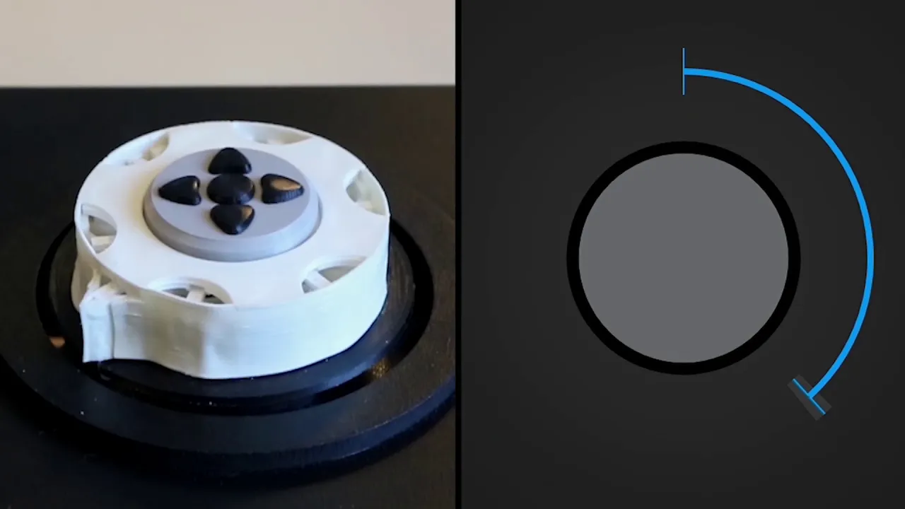




This video demonstrates how to create haptic textures and dynamic user interfaces using a PID controller with only the proportional term, where the controller output is clamped to create variable detents (clicks) at specific angular positions; the key parameters include the proportional gain (which controls how quickly the voltage increases), the detent angle (the position where the detent occurs), and the maximum voltage limit, allowing the same hardware to provide different tactile feedback experiences based on the application mode.
Implementing Haptic Feedback with SimpleFOC on a Brushless Gimbal Motor
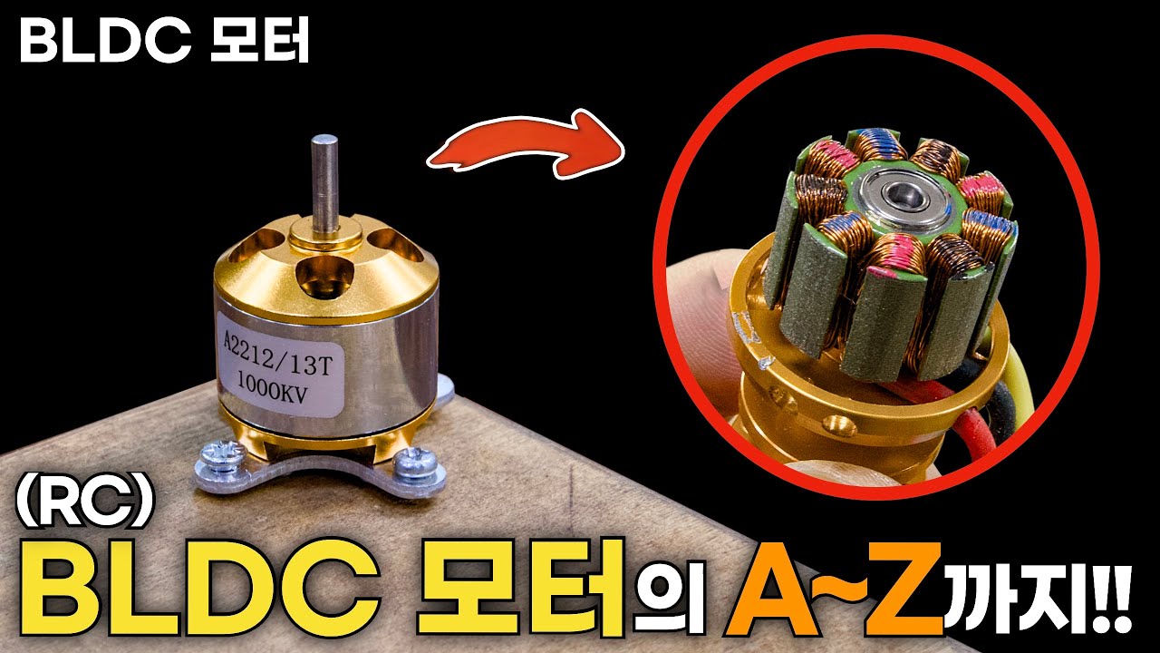
Added:Fundamentals of Brushless DC (BLDC) motors, particularly high-pole-count gimbal motors, and how they differ from standard brushed motors.
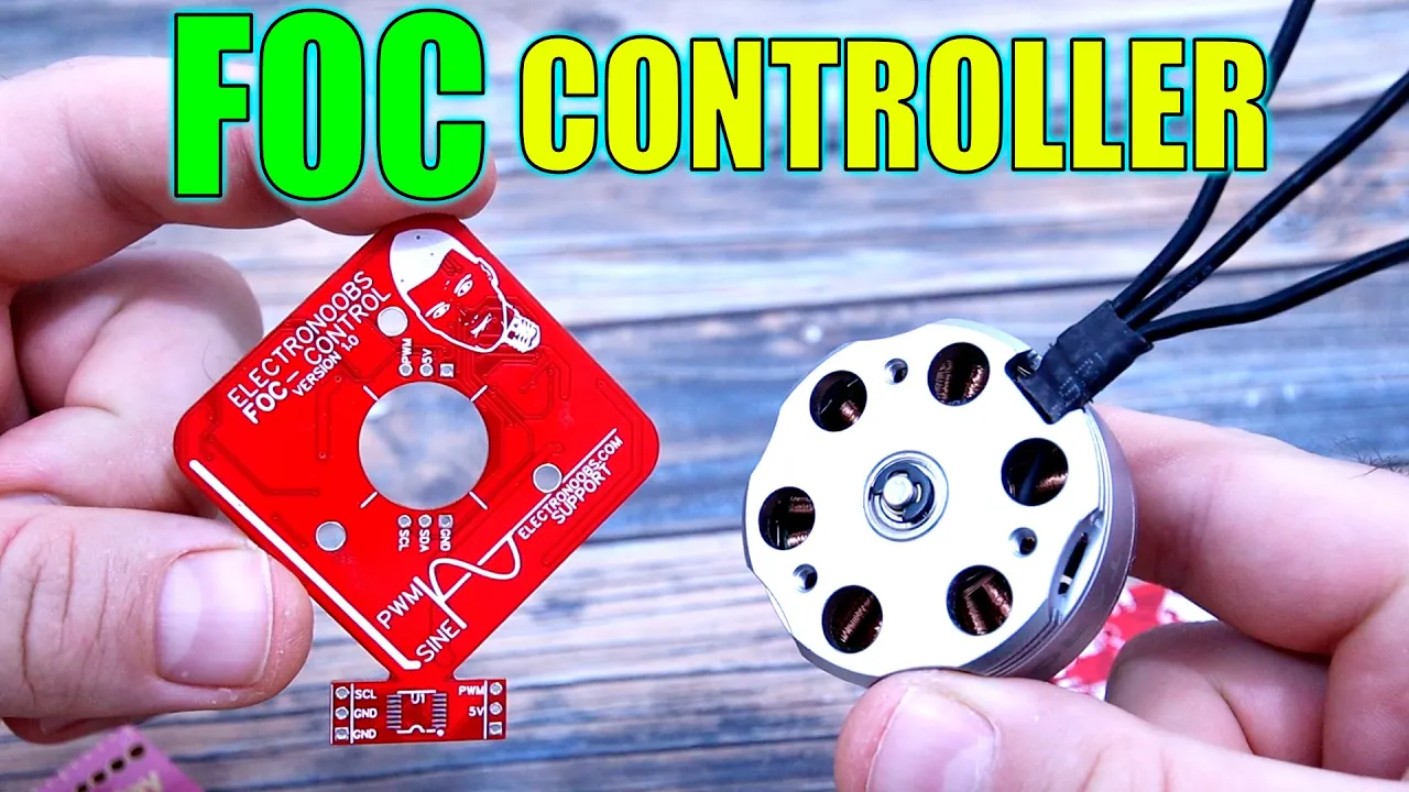
The core principles of Field Oriented Control (FOC) for achieving smooth, low-speed torque and precise angular positioning.
Basic Proportional-Integral-Derivative (PID) control theory, specifically how error feedback loops regulate position and velocity.
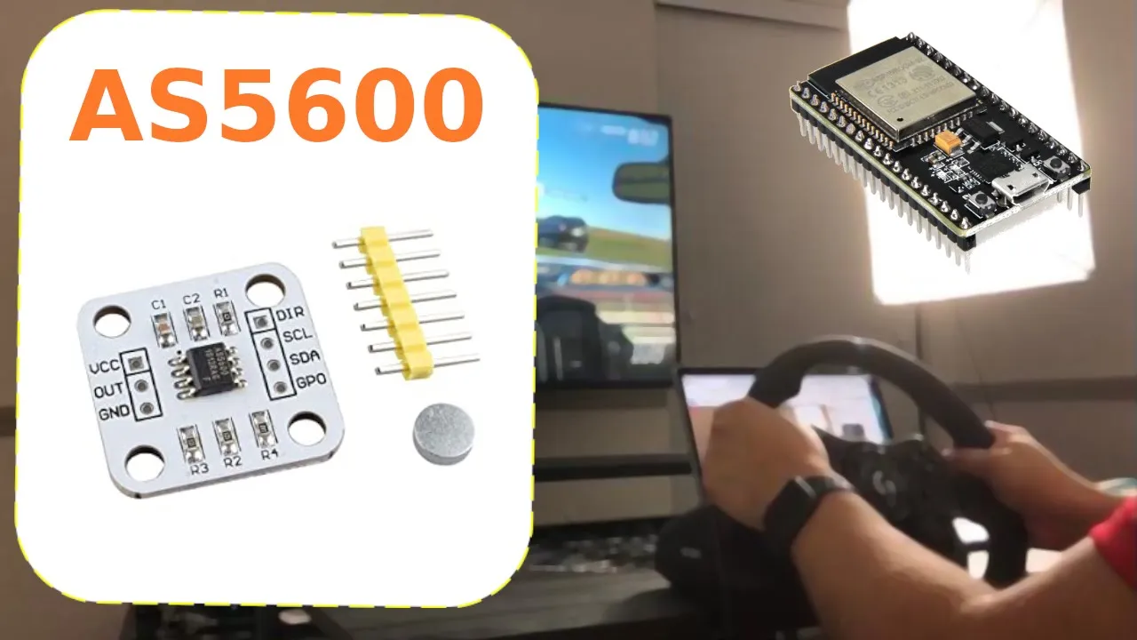
Microcontroller programming basics with the ESP32, including interfacing with magnetic encoders via I2C or SPI buses.
Mathematical modeling of advanced physical haptic effects, such as virtual springs, dampers, inertia, and complex friction models.
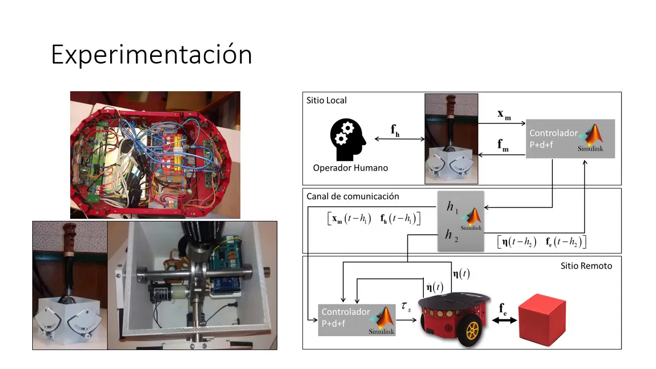
Bilateral teleoperation systems, enabling master-slave configurations where physical forces are bidirectionally mapped between two motors.
Designing smart interface devices, such as dynamic rotary input knobs, gaming wheels, or force-feedback flight simulation yokes.
Optimizing closed-loop motor efficiency using inline current sensing and thermal management algorithms under continuous stall torque conditions.
17.9K views640likes15:49Original Release: 2020-12-07
hey there internet welcome to part two of my haptic adventure so i wanted to give a little background clue you into how i got here i've been messing with cnc machines for a few years and while i'm very pleased with what i've been able to learn with cnc there's a bridge missing between manually controlling a machine and having the computer do some of the work for you and i've it's something i've wanted to explore in more depth and i've kept it in the back of my head over the past few years unfortunately it doesn't seem accessible for the hobby machinist back in march of 2020 i was browsing hackaday and i found a very interesting project called turn by wire they published a very interesting paper on a set of ideas to bridge this gap to give the operator a much closer connection to the machine it had my attention i read through the paper which was very detailed and had a lot of good ideas but there wasn't any source code that i could use and so i parked it in the back of my mind fast forward quite a few months in the interim i'd also been very interested in spindle synchronization implementations for gerbil unfortunately my c plus skills are abysmal and i have no background in control systems engineering to wet my teeth and to try to get some more experience i dusted off a two-year-old project that i had started for implementing an electronic lead screw for an esp32 and my manual lathe i wanted to refactor it and gain some additional experience while i was researching how to implement the algorithms i found a project called dige along the way and while it's a bit beyond my ability to understand the code it really helped me confirm my approach the project incorporated a very detailed explanation of the algorithms implementation and discussed in detail the differences between some of the common approaches that have been taken in different open source projects one of the nice things about an electronic lead screw is it is kind of the bridge between a manual machine and a cnc machine these things are fairly closely connected also in the intervening months i had done a prototype of a closed-loop brushless motor using a library called simple foc it was a great learning experience and i also discovered that the community around simple foc was very collaborative there was a forum where you could interact with the community and post questions and read other people's experiences with using the code base since i had joined the community i regularly get updates on what people are posting and earlier this week i saw a post about how you could use a very inexpensive l298 motor driver to drive a brushless motor with the simple foc code i asked for some sample code and the wiring and got a very prompt and detailed reply within a matter of minutes i actually had a working example up and running and i didn't really have anything in mind to use it for i just wanted to see if it would work it was seemed like a nice option to have in the in my back pocket so i left the test set up on my bench and moved on to other things the next day i guess google's algorithm was at work in the background and presented me with a very interesting video from a youtube channel called random access projects which maybe isn't the best name ever but the content's really fantastic the presentation was on haptic user interfaces the idea was could you have a single user input via a control knob that was powered by a motor that could give haptic feedback as well as adapt itself to the mode that the user was working in haptics are pretty interesting they're something that you use every day when you use your phone and you feel the phone make a slight vibration it's something i've been interested in a long time i think ever since i saw the novent falcon probably 15 years ago which was a 3d haptic interface for interacting with virtual worlds the video included a link to some source code which i didn't really understand my first thought was to try to do some implementation with the simple foc code base that i was already somewhat familiar with since i already had the test setup on my bench ready to go all i had to do was reprogram the controller i made an attempt it really wasn't very good but it was a good first step i went back on the forums and explained what i was trying to do i got a very quick and detailed response from the maintainer of the source code the author of the simple fac project the solution was very elegant and beautiful just a few lines of code and that's what i'd like to try to explain to you today is how that code works and how you can implement that code to create haptic textures and dynamic user interfaces that can change how they interact with the user based on what the user's task at hand happens to be here's a visual example of how the algorithm works the red line here is the gain of your proportional controller the blue line is halfway between your detent and that's the detent here is set to 10 degrees the purple line is the max voltage and in this case it's set to 12 volts and the green line would would show you the next d10 and you can just this would just go on forever i'm only showing the first two detents so the way that the controller works is as you increase the gain you increase the slope and the speed at which the voltage increases so if we set our gain super super high will have a very rapid increase in torque as you turn the knob so this would be zero degrees from where you currently are and as you get to one degree two degree three degrees you're already at the max torque and if you reduce the gain you'll get to some point at which you you know you don't even start to approach the maximum torque that the motor can apply so this would be a very soft detent in a soft click this would be the maximum detent click and going beyond that would have a period at which the motor is exerting the maximum torque before you get to you know you're going to increase the time before you actually get to the detent point at which the motor torque is going to go to zero and the d10 point will actually shift to the next point in this case 10 degrees if you change whoops don't change that if you change the detail angle you can see the effect that it has on the overall system so here very early on because we have a much larger detent very early on you're going to hit your max torque so you may need to make some adjustments to try to find where these lines intersect so that you can have a nice clicky feel if that's what you're looking for or again you can you can you can only use a portion of the maximum torque that the motor can apply so this is really how the code works visually hopefully this helps folks that think visually to understand how the code works uh other people will just be able to look at the code and intuit how it works this this is helpful for me since i tend to think visually it's also a huge struggle because i think i fell asleep in most of my math classes and trying to remember how to use functions on a graphing calculator has been quite a struggle so i'm sure there's a much more elegant way to do what i did here for folks who are adventurous maybe they can post a a desmos example in the comments below i'll walk you through it real quick these uh these are just the motor inputs and there's some initialization of the uh motor driver uh i'm using a library called neo timer which is a non-blocking timer library just to make the setting timers a bit easier uh this uh sets up the encoder so there's a rotary encoder an optical rotary encoder with 600 pulses per revolution that's attached to the gimbal motor [Music] here just setting up some pins these pins are mapped to the enable pins on the l298 uh here this is important if you don't have external interrupts you have to you have to configure it for an internal interrupt this initializes the encoder this uses hardware interrupts this line links the encoder back to the motor here we set the power supply voltage for the motor this is used to calculate the amount of torque and the amount of voltage that's going to be applied and then this links that driver configuration back into the main motor object the simple foc requires a initialization sequence so the motor will actually move around and look at the input from the encoder to figure out if everything's working correctly and it'll do some calculations to get everything initially set up so that it can control the motor there's several control types this voltage control type is is what simple fse is using right now for torque control so they're mapping or they're they're using voltage uh as a standard for torque because right now the well with the controller that i'm using it doesn't have any um it doesn't have any current sensing and there's no there's no feedback loop for the current so it has to use the encoder and the voltage that's being applied to derive uh an approximation of the torque this is just normal setup of the serial you can link the serial to the motors monitoring functions and then these are the two initialization routines that gets the gets everything set up and ready to work uh you can ignore this this is just uh some auto pid tuning stuff so this is this is the real magic this is this is a instance of the pid controller class called pid haptic and uh we're creating this pick controller class with one term the the proportional term and we're leaving the integral and the derivative terms off so when you set those to zero those those are not used there's an output ramp that is the how quickly the voltage will increase given a time period and then there's a limit which is the limit in voltage this attract angle this will change as the system changes you initially set it to zero and when the when the motor gets initialized the angle will be set to zero the attractor distance this is really just taking the 10 degrees for each d10 point that we want to use and translating this into radians then we define a function called find attractor and this this is what this essentially will uh take the attractor distance which is again in radians and uh calculate based on the current angle the uh the attractor so uh based on where the current angle is let's say we're doing this uh 10 degree detent when you get to 5 degrees it'll shift the attractor to the next d10 point then in the loop we run this loop foc command this is what will this loop foc command needs to be run as quickly as possible uh the motor move command is fed with the output of the pid controller and the input to the pick controller is the attractor angle which is calculated every loop minus the current motor shaft position which is this motor.shaft angle and then the attractor angle gets recalculated the serial event allows me to configure uh different things so in the demo you'll see me go ahead and change the the degrees per detent and that's through the uh the serial input and then there's a motor monitor which will just spit out a bunch of data you can graph the data or do whatever you want with it this is not necessary for for anything other than tuning the pids and looking at how the system is reacting 100 detents per revolution 36 detents per revolution eight detents per revolution softer detents two detents one detent dangerous detent well if you've made it to the end thanks for watching if you skipped ahead no problem this has been a really long video if you have any questions leave them down in the comments below and hopefully this helps somebody better understand some of the capabilities of simple foc and haptics
Up Next

53:43
Field Oriented Control of Permanent Magnet Motors
@TexasInstruments
366.6K views•2012-08-29

30:32
Ultrasonic Transducers: Resonant Frequency Measurement and Horn Design
@imajeenyus42
229.9K views•2017-02-22

54:16
Polymer Environmental Degradation: Mechanisms & Stabilization
@iit
1.8K views•2012-07-10

33:39
How a Student's Question Saved a NYC Skyscraper from Collapse
@veritasium
22.8M views•2025-04-26
Related Study Plans & Knowledge Roadmaps
Structured learning paths in Engineering
engineering
Building Acoustic Levitators: Physics & Arduino
01The Physics of Sound and Standing Waves
02Piezoelectric Transducers and H-Bridge Drivers
03Arduino Programming: Generating 40 kHz Signals
+ 2 more learning modules
14h5 modules
Explore Roadmap
engineering
Building Peltier Cloud Chambers: Particle Tracks
01Cosmic Rays & Cloud Chamber Physics
02Thermoelectric Cooling (TEC) Fundamentals
03Custom Liquid-Cooling Loop Design
+ 2 more learning modules
18h5 modules
Explore Roadmap
engineering
Yagi-Uda Antennas: Modeling, Build & VNA Test
01Introduction to RF and Antenna Fundamentals
02Yagi-Uda Antenna Design Principles
03Antenna Modeling and Simulation in 4NEC2
+ 2 more learning modules
18h5 modules
Explore Roadmap
engineering
ECG Monitor Design: Op-Amps, Filters & Noise
01Electronics & Breadboard Basics
02Op-Amps and Instrumentation Amplifiers
03Bioelectricity and ECG Fundamentals
+ 2 more learning modules
18h5 modules
Explore Roadmap