



![[SOLDERING STREAM] Learning to solder :3 Results may vary ✨](https://i.ytimg.com/vi/TdJvYGc1sis/maxresdefault.jpg)


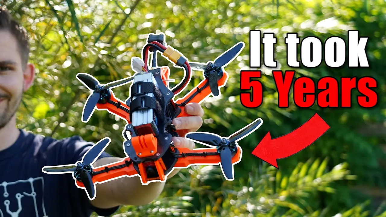
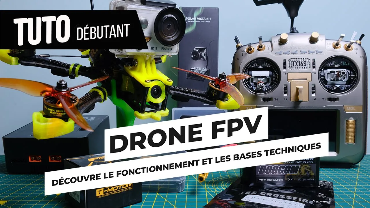






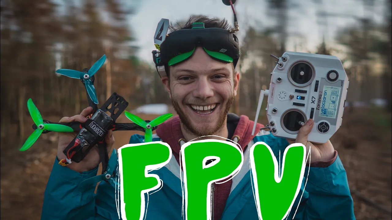
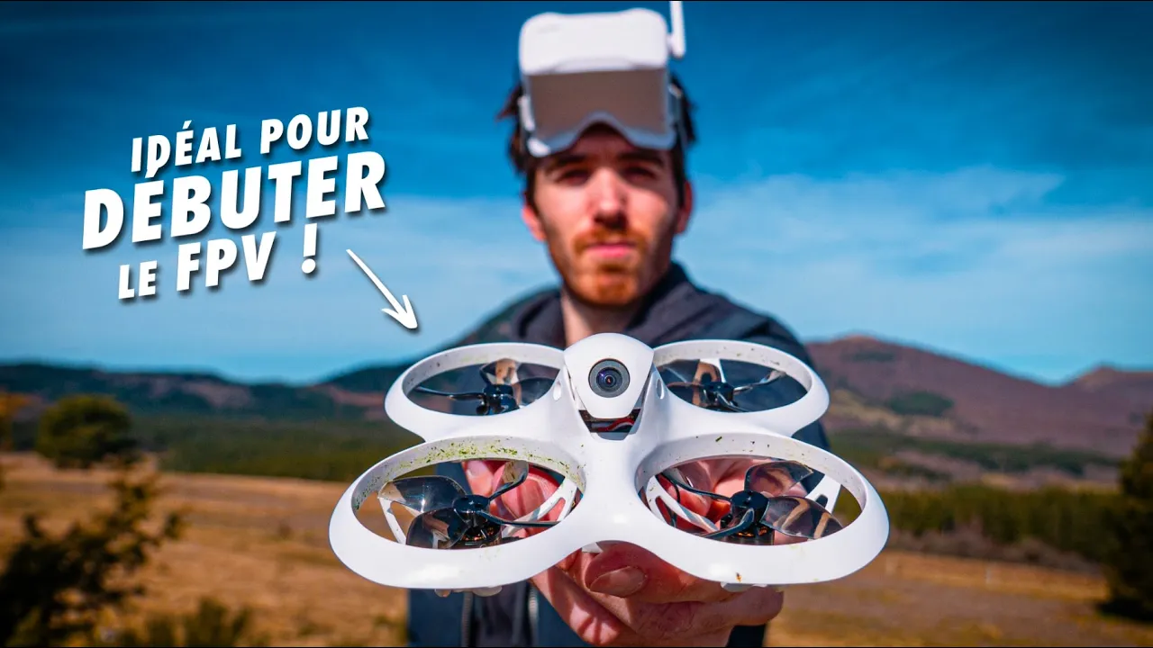







Building an FPV drone involves systematically assembling the frame, installing motors and ESCs with proper soldering techniques, mounting the flight controller with vibration isolation, and wiring the video transmitter and receiver while ensuring all electrical connections are properly insulated and secured to prevent shorts and ensure reliable flight performance.
2022 Budget FPV Drone Build: Full Assembly Tutorial for Beginners
Added:Basic electrical engineering principles, including voltage, current, resistance, and polarity.
Fundamental soldering techniques, safety protocols, and the proper use of flux and solder.
Anatomy of an FPV drone, specifically the distinct roles of the Flight Controller (FC), Electronic Speed Controller (ESC), motors, and receiver.
Safety precautions for handling and storing Lithium Polymer (LiPo) batteries.
Advanced flight controller configuration and PID tuning using firmware like Betaflight.
Principles of radio frequency (RF) propagation, antenna polarization, and video transmitter (VTX) power management.
FPV flight dynamics and pilot training, beginning with software-based flight simulators before real-world flight.
Troubleshooting electrical noise, motor desyncs, and performing routine hardware maintenance and crash repairs.
National aviation regulations and safety guidelines, including drone registration, licensing (such as the FAA TRUST or Part 107), and airspace restrictions.
346K views5.1Klikes1:04:35Original Release: 2022-06-07
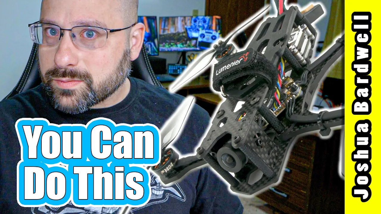
this is the jb xylo budget build kit and in 2022 when everything is super expensive it kind of hurts me to call it a budget build kit but we did our best to get the price as low as we could while still giving you good value not making too many compromises on the performance and durability of the kit and the reason i think this kit is so significant is that there is no way in the hobby of fpv to avoid building your own quad what do you mean you could just buy a ready to fly and fly it yeah but you're gonna crash it you're gonna break it and then you're gonna need to fix it unless you're planning on buying a whole brand new quadcopter every time you crash you're gonna need to know how to fix it and the best way to learn how to fix a quad is to build one because then you go through all the steps of putting it together and you that's the best foundation for how to build repair and maintain your quad so in this kit we have selected we think are pretty good parts and i am now going to walk you through the process of building it step by step that's it let's do it now here's all the stuff that comes with this kit and since the assumption is that this might be your very very first build i want to take you through each of the parts and talk about what they are and what they do the frame is the qavs joshua bardwell edition this is my own little custom version of the lumineer qavs frame and i think it is a really good combination of lightweight durability ease of maintenance and so forth here we have the flight controller and the electronic speed controller of the quadcopter also known as the fc and the esc you'll almost never hear people say electronic speed controller out loud they just say esc the flight controller is essentially the brains of the quadcopter it takes all of the inputs from your controller sticks from sensors like a gyroscope and an accelerometer and it it basically decides what the quadcopter needs to be doing at any given point in time and then it sends commands to the esc and the esc's job is to make the motors spin that's the only thing esc does it just makes the motor spin the motors are xylo stealth and they are 2207 in size which is a really popular size for uh this type of quadcopter the kv of the motors that i'm using is 1800 kv and that means that they are intended for use with a six cell battery if you have four cell batteries that you know you want to use then they are also available in i believe it's a 2400 kv version for four cell batteries if you're not sure i would say most people would start with six cell batteries today most people would end up with six cell batteries so you may as well start there and not waste money buying a bunch of four cell batteries that you're not going to use but if you have four cell batteries already that you think you're going to use you could get the 2400 kv version well motor's not going to do much without propellers and we've included three sets of props with this kit they are the jb gemfan 51477 prop and as you can guess from the fact that it's got my name on it it comes with a little jb sticker these are my personal favorite prop for the type of flying that i do but don't think that you can't branch out and try other props in fact especially if you're getting started in the hobby i would suggest that you try lots of different props and see how they fly differently and which one feels the best which one fits your budget the best but we've included these three just to get you started now as this is an fpv drone it's going to need to have a camera on board and a wireless video transmitter to send the video feed from the camera back to your goggles so you can see what the drone is doing and fly it and there's two choices in this build series that we're going to show you how to build the first is the dji nebula pro vista kit this is a high definition 720p uh system made originally by dji and now made by caddix and it's going to be the choice of people with a little bit bigger budget it's just significantly more expensive than the analog system the analog system is going to have a catex retell camera and the xylo stacks video transmitter and basically this is going to be like standard definition like old television from the 80s is kind of what it looks like it's lower quality image but it's significantly less expensive and that's the main appeal of it we're going to show you how to build both and then finally we've got the controller and for this tutorial we're going to be using the radio master xoro with express lrs receiver or if you're installing the dji video transmitter you could choose to use the dji controller there are others you could use but these are the two we're going to cover in this tutorial the first step in this build is going to be to assemble the bottom plate and the arms of the frame we're going to start with this piece i want you to note that this piece has these press nuts pre-installed in it it is not the same as this piece which looks very similar but doesn't have any press nuts we're going to take that piece and we're going to turn it over so the press nuts are facing the table and i want to show you how the arms fit onto this piece before i start putting screws in so each arm has a hole here and it's going to go into a screw hole here and they're going to line up and the arms are going to go together here's a screw hole here the arms are going to go together like so next i want you to find this x plate and this x plate is going to fit down in between the arms like so and it you can see it has two screw holes here and they're going to line up with these press nut holes in the frame and then finally you're going to have these two little arrowhead pieces and they will go in here and line up with the press nut screw heads there now i'm going to actually put this together with screws and it won't all shuffle around like it's doing but i want you to see the final picture is going to look like this but with screws in it okay let's start putting it together next i want you to go into the strip of screws and hardware that comes with the kit and i want you to find four 16 millimeter m3 screws there's another pouch with two 12 millimeter m3 screws and if you open up the pouch of standoffs you'll see that there are two long standoffs which we're going to set aside and i want you to get four of the short standoffs next we're going to take this plate which does not have the press nuts in it and this plate is symmetrical it does not have a top or a bottom so it doesn't matter which way up it goes we're going to take those 16 millimeter screws and we're going to put them 1 two three and four we're going to flip that over and just set it on the table so the screws don't fall out we're going to put the arms on one two three and four we're going to take the x plate and this also is symmetrical there's no front or back top or bottom we're going to put that in like so we're now going to take this plate which does have the press nuts in it and with the press nuts facing upwards we're going to put that over the arms and down through the screws let me take a little wiggling and get it to go and then we're going to take the four standoffs and we're going to put them loosely on top of the screws to hold sort of hold everything in place now at this point the frame almost looks like it's put together but the arms can flip out like so and that's what these little arrow hits are for so the arrowhead is going to fit in here 12 millimeter screw is going to go through the arrowhead and into the captive nut and that will provide tension that will keep everything locked into place now you may find that you have a little bit of trouble getting this to line up and go into place it has to be tight otherwise it won't be doing its job and the arms will be loose so you may need to kind of wrench on this a little bit and squeeze it like squeeze these arms out to cinch them down and squeeze these arms in a little to cinch them down kind of press on this and try to get that screw to go in you should be able to get it in snugly but it may take a little bit of work and once that's done you can go ahead and cinch down on all of these screws hey there folks joshua from the future here don't make the mistake that i've made i want you to see that the x plate right here the x plate is pressed up against this bottom plate here that's not how it needs to be if yours is like that you're going to need to sort of loosen everything up and kind of wiggle it and shake it and push it until it moves i'll show you how it needs to be i'm just going to push it here so it's flush with that with that plate and now you can see that the x plate here is flush with this top plate not this bottom plate that's how you want it before we go any further in this build i want to say a word about thread locker or loctite quadcopters are subject to a lot of vibration and stress and as a result the screws on them tends to back out if they're not perfectly snug in fact it's common practice after your first couple flights and your first couple crashes to go back through with your driver and re-snug all of the screws now you're not going to see me putting loctite on every single screw in this build because this build is already going to take long enough for me to record and it would slow me down even further but a lot of people would advise you and it's good advice that you should lock tight your screws if you decide to do this there's first of all make sure that you're using the blue loctite because the red loctite is permanent it requires a heat gun to release it and you just can't take the screws back out again the blue loctite is semi-permanent and you can back the screws out again but it will keep them from loosening with vibration there's two types the liquid type is just a little bit more messy but it's a little bit easier to put a nice thin layer of the liquid on there but i like to use the stick type it's just like a glue stick and you just kind of dab the screw just the tiniest bit as necessary you dab the screw on the stick and then you put the screw in and that's what i would recommend you use if you're doing this build and you want to cover all your bases next we're going to install the motors and each motor is going to come with a little bag of accessories there is one prop nut that is the large nut that's in there and then there are four small screws that are going to be used to hold the motor on the arm i suggest you just take that prop nut and loosely install it here on the motor just so it doesn't go anywhere orient the motor so that the motor wires come out and down the arm and then just hand place all of the screws before you go back with a 2.5 millimeter driver and tighten them down incidentally uh if you are a typical american then you probably don't have a nice hex screwdriver set like this you may have an old set of allen wrenches you know laying around these hex screwdrivers are super nice and you're going to use the hell out of them in this hobby i'll put links in the video description to some kits you could pick up to get you started on your tools now as you tighten these down be aware that the base of the motor is made of aluminum whereas the screw is steel and what that means is that you could easily wrench this with your hand and strip this out if you're a big freaking gorilla so yet another reason to use loctite so that you don't have to rely on over tightening the screws to get them to stay in place you definitely want them nice and snug but don't go crazy you can strip it next we're going to go back to the hardware that came with the frame and we're going to get these 22 millimeter screws there are four of them now the mounting holes for these screws are here on the bottom of the quadcopter and you can see that they each have a press nut that they're going to screw up into on this plate the reason that there are two sets of mounting holes is that hardware used on quadcopters comes in two at least two common sizes 30 millimeter or 20 millimeter mounting the inner holes are for 20 millimeter hardware the outer holes are for 30 millimeter hardware and we're going to be using the 30 millimeter holes so i'm gonna take my four 16 millimeter screws and put them into the outer holes and screw them in through the press nuts in the bottom of the frame next we're gonna go to this little accessory bag that comes with the kit we're gonna get out these four black rubber o-rings and we're gonna put those down one on each of the screws and and after that we're going to take the esc make sure you've got it this side up not this side up and we're going to gently press the esc down onto those mounting screws and as you do that make sure that your blue silicon they call them gummies they're for shock and vibration isolation make sure that they are still in place they didn't like come out in the bag or something and as you press them down make sure they don't like scooch up out of the esc i'm just going to press that down and with the esc in place you can see the reason that we put those o-rings on is to give it just a little bit of separation and see those press nuts stick up just a little bit and we wouldn't want one of those metal press nuts to touch the esc and potentially short-circuit it and damage it so you never want your esc to be too close to your frame next we're going to take the motor wires and we're going to lay them flat on the top of the arm we're going to use the included zip ties to zip tie them down to the arm and we'll cut off the zip tie with a diagonal cutter now we come to what might be the most difficult part of this build for many people and that is soldering yeah you see these wires here you see how there's no plugs on the csc and there's no plugs on these wires we're going to have to solder the wires to the esc and if you don't know how to solder at all this is going to be the part where you are going to need to pause the video i've got a soldering tutorial linked down in the video description go down to the video description watch that soldering tutorial get decent at soldering or at least not like just your first day soldering and then come back and finish this build because if you don't know how to solder and you just dive in you're just going to destroy this stuff and waste your money now this is not a soldering tutorial this is i'll give you some tips and tricks as we go but i'm not going to teach you every single step of the way because i'm going to assume you've at least got a couple hours of soldering under your belt if not more and i'm going to start by applying this no clean liquid electrical flux which is a chemical that makes you better at soldering that's the gist of it and i'm going to set my iron i've got my iron at a temp of 850 fahrenheit which is as hot as it goes and i've selected the soldering iron tip that i think suits this work best go watch my soldering tutorial if you want to hear more about that i'm going to first tin these pads by adding a small amount of solder to the pads and then i'm going to cut the wires to length and prep them for soldering down and what i like to do when i'm cutting wires to length is i'm going to hold them about how i think they're going to actually run and i'm going to leave myself even then just about a millimeter or two of extra length so that's basically how they're going to run and then i'm going to come in here and give myself just a little extra length because i usually lose a little bit of length as i prep them and the wires are going to go i got three wires and the three wires from this back left motor are going to go one two three to these back left pads one two three for the front left one two three for the front right and one two three for the back right each motor has three wires three pads and you're going to notice that i lay these wires down flat and i solder them to the esc one two three by laying them down flat the order that you saw to the wires actually doesn't matter it does have an effect but we're going to sort that out later and basically all i'm going to do is lay the wires flat and keep them neat looking so that my build looks clean next i'm going to strip off about two millimeters of wire i'm gonna twist and then i'm gonna add some solder to the tip of that wire and i'm going to solder down the wire and now i'm going to do all 12 of these wires three for each motor each wire going one two three one two three to the different corners i'll show you what it looks like when i'm done and here is basically what it should look like when it's done um you'll notice that i haven't quite gotten the length of the wires perfect there's a little bit of extra wire here i've pulled the slack here a little bit i don't want it too tight here because i don't want to have any stress on this joint but i did take some of the slack out so it's not if these wires are sort of flopping up here they could get chopped by the prop i have to say i might if this was my own build i might choose to put some tape on here instead of zip ties i'm looking up here there's a kind of tape i like to use it is wire harness tape and it's very good for this you can also use good old electrical tape as well and it can wrap the whole arm and keep the wire down and out of the prop but zip ties are fine i've just sort of tugged it a little bit to take just a little bit of the slack out and that's what we're going to end up with let's take a closer look at the solder joints themselves and the thing you're going to want to look for for sure is that at no point do any of the solder joints touch each other there is no connection between the individual joints whether that be solder whether that be a piece of wire sticking out they are all independent of each other if you plug in a battery and try to fly with two of those touching then the best case scenario is you smoke a motor and the worst case scenario is you smoke the esc so make sure that you haven't done that and correct that if that's if that's happened before you plug in the other thing that we want to see is that the wire itself does not extend past the solder pad so we've cut about one maybe two millimeters of wire at most and that is what we've got here and the insulation of the wire goes all the way up to the edge of the solder pad and we don't have a big length of wire sticking out this direction with no insulation on it because again if those two cross over then you're going to smoke something if any of that is true if you're struggling with this then it's time to go watch the soldering tutorial that you thought you didn't need i don't want to sound like a school marm lecturing you but if you can't solder you're going to struggle and you're going to waste money in time and blow things up okay next up the xc60 lead the xd60 lead is the main battery lead it comes in the box with the esc we're gonna have several different components here we've got a couple capacitors we've got the wire for the esc we're gonna come back to that it's like we got a couple extra gummies if we need them and these are the things that we are going to get out right this minute and we're going to be working with and now to help make it easier to solder up the 6060 i'm going to pull out this omnifixo helping hands tool it's pretty freaking cool i've got a video about it that'll i'll link that down in the video description too if you want to check it out it's magnetic they hold their position they go all around if you don't have something like that you can get some of this uh it is called fun tack or blue tack and it is a kind of goopy blue thing you just mush it up into a glob and stick your wire in it and it holds it in place but i'm going to be using this helping hands tool this is an xt60 connector and it's the main plug for your quadcopter and your batteries are going to come with it as well and i want you to notice that it is marked with a minus and a plus symbol and in addition it has a flat side and a curved side the curved side is minus the flat side is plus but we're just going to go with these markings the next thing i'm going to do is i'm going to take my tool and i'm going to rotate these they just their friction fit in there and they will rotate so that they cup faces upward like so that's going to make it easier to solder to i'm next going to put some flux on these as always and then i'm going to basically fill these up with solder next i'm going to take the wires and the wires are pre-cut and pre-tend but we can always make life a little easier for ourselves by getting a little bit of flux on the end of the wires you're going to do both ends because you're going to solder both ends and i'm going to add some fresh solder here because the solder they use at the factory is lead free and it's not as good quality as this good old leaded solder that i'm using at home destroying the environment so be it and then we're going to line this up and i'm probably going to need to press this into place i'm not just going to be able to use the third hand tool to hold it so i'm just going to get this ready to go i'll get my little tweezers out here and i'm going to complete this joint let me turn it sideways for the second one so you have a better view looks pretty good to me [Music] once again we definitely do not want to see any connection between them next we're going to take this little plastic cover and we're going to slide that down and before we pop that on there let's just take this opportunity to double check that the red is on the plus and the black is on the minus yeah that's the correct way to do this red is positive black is negative and we'll just pop that into position now we're going to need to solder this to the esc and the main battery pads for the esc are these two large pads here but before we solder it down let's think about where the wire is going to go and a lot of people would run this wire out the back of the quadcopter like so but there's going to be stuff back there and especially if you're doing the dji version of the build there isn't actually that much room for it to go for the wire to get by it so i like to run the wire out the side like so and that i think is what we're going to do as before we're going to tin to begin the ground pad the negative pad especially takes a lot of heat before the solder will flow if your soldering iron is not quite good enough you're going to really struggle to make it flow we're going to add some flux here that'll help us a little fresh solder here on the wires before you solder down the xt60 lead i want you to take two of your cut off left leftover motor wires i want you to solder them as i'm going to show you here to the negative and positive pad i'm going to solder them just to the side and i'm going to show you what this is for later in the build and you notice i passed them toward the front of the quadcopter like so joshua from the future here uh when you get to the spot in the build when you are going to do something with these wires you're going to need to know which is the positive wire and which is the negative wire and you can see right here because they're all stuffed up in the build it's not obvious which is which so i'm going to suggest that you mark in some way like i'm going to take a little piece of red electrical tape and i'm going to mark the positive wire with that red tape just so i know which is the positive and which is the negative yeah if i had just used colored wire this wouldn't be a problem but i wanted to use the spare motor wire since i was to never use for them anyway and so they're both black and i don't know which is which mark the positive wire somehow and i'll see you in the future when you find out what we're going to do with it and then i'm going to come in and solder the xd60 lead and again look very closely here we've got a minus and i've covered it up slightly but we've got a plus here this is the negative on the left and the positive on the right negative is black positive is red and the challenge for this part is going to be soldering on this big 14 gauge wire without desoldering this little wire that we've soldered on and it's going to be a little bit of a challenge for some people but we just got to figure out how to make it work and here is where we're at next we're going to install the flight controller now if we just take the flight controller and mount it on top of the esc they're going to be too close together they're going to touch and just like i said when i was mounting the esc and i didn't want it to touch the the frame we don't want that to happen the electricity could go where it shouldn't go and bad things could happen so i'm gonna grab some of these extra silicon gummies that came i think they were in the little accessory bag i think you should have four extra gummies and we're gonna slide those down on top of the esc and we're going to see if that gives us good spacing where's my fourth one there it is yes now if you're doing your own build at some point in the future and you don't have extra gummies you can use something like these m3 nylon nuts uh in fact you could even just go buy a set of m3 hardware or m3 nuts the disadvantage of using a nut is that it's threaded and you really would like them to just slide down on top of the screw instead of having to constantly thread them down now when you mount a flight controller the direction that the flight controller is facing does matter because the flight controller is keeping track of how the quadcopter is moving and how you're commanding it to move and so the flight controller needs to know that this direction is forward this direction is left and so on every flight controller is going to have a forward facing arrow here's the forward facing arrow for this one it's a little bit stylized but it tells you what direction the flight controller thinks the front of the quad is in and if for some reason you're building a quad and you need to mount the flight controller facing another direction that's okay that you can reconfigure it in software but it's a good idea to just do it that way if you can so we're going to identify the front of our quadcopter and that is this part you can identify these four cutouts here which are going to be for the camera side plates and we're going to mount the flight controller on the stack facing that direction again just like with the esc make sure the gummies don't pop out and then we're going to take a look and we're going to see if we have enough spacing to make this work hey there joshua from the future with another correction uh yeah why on earth would you ever need to mount your flight controller not facing forward well one reason is that the plug for the esc is right here on the flight controller but the plug for the esc is on the front of the esc why did they do it that way i don't know but it sure seems like we got to either flip the esc around or we gotta flip the flight controller around and uh of those two i know which is gonna be the easiest to do the cable is keyed it only goes in one way if you're having trouble pushing it in flip it over maybe as you're pushing it in the wrong way notice what side i'm putting facing up versus down and then the other end is going to go into the esc we're just going to flip over like this and let's just give this a little twisty twist to take some of the slack out and we're going to mount it like this facing perfectly backwards this asc and this flight controller are actually designed to work together so it's pretty weird that it's pretty weird but okay let's just uh get on with our life now joshua from the past is going to tell you how to put these nuts on how hard could it be to put nuts on a screw huh well you'll see and if i take a look here it looks pretty good there's plenty of clearance there for the wire that's going in between them no part of the esc is touching or even really close to touching any part of the flight controller i think this is going to work just fine now there's more reasons than you might think why the flight controller needs to be isolated or separated from the rest of the build previously we talked about how if some part of the flight controller or esc touched something else then electricity might go where it's not supposed to go and you would you would fry it or burn it with the flight controller it has a sensor on board called the gyro or the gyroscope and that sensor detects vibration and rotation and the problem is that the motors create a lot of vibration as they rotate they're spinning at like 30 000 rpm in some cases and that makes a lot of vibration and that makes the flight controller have a harder time flying the quad good so that's why we go to great effort to soft mount or vibration isolate the flight controller using these gummies and then we don't want to defeat that by having something like a piece of wire or something touching the flight controller from somewhere else and then transmitting vibration to it and that's why we want to make extra sure that nothing is pressed up against or touching the flight controller and then i'm going to take a couple of these screws and i'm going to tighten them down before i forget you can do that by hand or i have a nut driver that is the right size for these it is a 5.5 millimeter nut driver and again it's a i got some tools listed in the video description if you want to pick them up we're going to tighten that down until it just begins to compress the gummy we don't want to over compress the gummies because that will defeat the purpose of the vibration isolation so we definitely don't want the flight controller to be at all loose we don't want it to be at all able to sort of well it can't move you can see there if i squish the gummies it can move but i'm squishing the gummy so i don't want to do that we definitely want it to be kind of snug but not so much that we're crushing or deforming the gummies and defeating the purpose of that vibration isolation and again after you tighten those nuts down look between the boards again and just make sure that nothing is crushed or crimped no wires are stuck in there the esc is still not touching the flight controller because they've gotten a little bit closer together and if they were just on the edge before now they may be touching i know it probably seems like i'm making such a big deal out of this point but the flight controller is a huge part of your quad flying well and without trouble and mistakes that people made when they're building their flight control stack little silly mistakes that they don't notice can make like the whole quad fly badly so this is just as important as i'm making it sound next we're going to wire up the video transmitter and this chapter of video is only going to be for you if you are doing an analog build if you're doing a dji build down in the video description and in the timeline at the bottom of this window there is a chapter a table of contents and chapter markers and you can go down there and you can skip to the chapter about installing the dji video transmitter for those of you who are doing analog here's the next thing we're going to do this video transmitter comes with mounting holes and they are 30 millimeter in size so in theory you could mount it on top of a flight control stack like this but you can see there's not really enough room there where when the top plate goes on there's not enough room for that stack that's okay there's plenty of room to mount it in the back of the quad but since we're not going to be using these we're actually you can see if you look carefully they are scored and we're going to just break them off so i'm just going to grab it with my little forceps here and just break it off carefully all four of them we're going to break off the video transmitter does not come with its own wires so we've provided a set of wires for you in the little accessory bag and there are four wires there a red a black a yellow and a white here's where those go on the video transmitter the black wire is going to go in the ground pad and since these are through hole one way that you can solder them is to just stick the wire through the little hole and then come in [Music] with a piece of solder and just come under like that so here is the final wiring for the video transmitter the black wire goes to the ground pad red wire goes to the v-bat pad white wire goes to the sa pad nothing on the audio pad yellow wire on the video pad and then nothing on 5 volt out or ground that's the correct way to wire that up coming back to our flight controller we've got pads here in the corner labeled vtx sa power and ground and those are going to be for our video transmitter and when i soldered up the video transmitter it was relatively easy to put the wire through from one side and then solder on the other side but for the flight controller it's much more difficult to get to the underside with the flight controller mounted so i'm going to use a slightly different technique to solder these i'm going to just basically treat them like they were flat pads without holes i'm going to tin and then i'm just going to come in and solder the wires down you see how this wire here is much larger than the pad that i'm soldering to and it will either hang off the end this way with a length of unshielded or uncovered wire or if i push it all the way here it will stick out and hang out the end this way that's no good we generally want the amount of exposed wire to roughly be the same size as the pad we're soldering to or maybe just a smidge larger but that's too much let me check these other wires yeah they all they're all way longer than we really need them to be i'm gonna nip them down here and in the end what you should have is yellow wire to vtx white wire to sa red wire to power black wire to ground as far as mounting the video transmitter goes this is a case where i don't think the kit comes with what i'd recommend you use in fact i'm not sure it comes with anything maybe we'll fix that by the time the kit ships but i'm not sure what i suggest you use to mount the video transmitter is this stuff it is scotch extreme mounting tape you don't have to buy a giant 300 foot spool like i have because i go through the stuff it is a really good sticky double-sided tape and it can hold that video transmitter in place there's a link in the video description if you want to pick a roll of it up and before i mount the video transmitter down i think i'm also going to install the antenna i mean that is a connector that it's using is called mmcx and the way that it works is it just presses in here with a little snap there we go there we go then i'm going to take my double-sided sticky tape i'm going to put it on the underside here and you know i'm just going to cover up these pads with it because i don't want them to touch the carbon fiber and turn this over and let's just give this a couple twists to take some of the slack out and we're just gonna press this down here make sure you don't cover up the mounting holes or the standoff holes here in the back though give it a little press and a little wiggle and it will stick pretty gosh darn securely i'm also going to install this antenna and the reason for that is that if you power up a video transmitter with the antenna removed the video transmitter can be damaged so although i'm not quite ready to mount this antenna in its final location i'm just going to go ahead and plug it in just in case like i power up the quad for some reason i don't want to accidentally damage the video transmitter now it's time to install the dji video transmitter and camera and just like i said previously when we installed the analog camera and video transmitter if you're not using dji there are chapter markers and timestamps down in the video description and in the timeline below this video and you can just skip to the next chapter the other thing i want to point out is that i have actually finished this build with an analog i finished the analog build and now i've taken the analog stuff back out again to put the dji in and so if you notice that a few things are different like i've already mounted this receiver but you may not have seen me do that yet so it's going to be a little bit out of order for you but it'll be fine we'll get through it i'm going to take this bag of accessories that the vista comes with and dump it out and we're going to get this wire harness and we're actually going to need to install this wire harness on the vista with by soldering it sad to say wish it could come pre-soldered but it doesn't right here on the catx vista are the pads that we're going to solder to and i want you to take note of the order that they go in on one side we've got a pad labeled s bus on the other side we've got a pad labeled v for vbat or battery input and the colors of the wires in the wire harness are going to line up with that we're going to start with the red wire on one side and go through to yellow wire on the other side and again although this is not a soldering tutorial per se this is a fairly fiddly little piece of soldering because you kind of have to come in at an angle with your iron tip and you don't want to be like touching or messing with the rest of the vista i confess that since this is intended to be a oh your first build i feel like this is fairly advanced soldering for your first build but just is what it is there isn't really any way around it we could use the full-size air unit which has a plug but then the whole frame would need to be redesigned and i just welcome to the hobby to help me out here i'm going to add just a little bit of fresh solder to each of the wires even though they are prepared they're pre-tinned and pre-cut to the right length adding a little bit of fresh solder will just help this go easier and then to make my life even easier i'm going to add some flux some liquid electrical flux which you certainly own don't you if you're so good at soldering that you don't need to add extra flux then good for you now normally i might skip over this section or speed it up because making you watch me solder a bunch of joints isn't necessarily the point of this build but in this case the technique is pretty fiddly and i want you to see exactly how i do it with the tweezers i come in and hold the wire exactly where it's going to be and then i kind of come in from the top at an angle and use the iron to melt the solder and hold the wire in place and i'm working towards myself so that i can see where the iron is as and the other wires i've soldered aren't getting in the way i hope this helps you get it uh it just is what it is and i wish you the best of luck if you don't feel confident with it then i would recommend that you practice more of this kind of joint on something other than an expensive dji video transmitter that you might ruin when you're done this is what you should have and definitely make sure there aren't any solder bridges between the two pads next we're going to install the antenna and i like to put the antenna on the vista before we mount it inside the quad for reasons which will become apparent the antenna goes here and there's this little metal bar holding it down so it doesn't come unplugged by accident uh and the way that i like to install it is to remove this screw entirely this is a 1.5 millimeter hex screw and then we're just going to slide this out revealing the connector that connector is called a ufl connector before we pop that down we're going to get this 3d printed piece which is the antenna mount and we're going to slide this through yeah can't do that after you install it we're going to slide that through and press it down cool then i'm going to pop this on and just feel that it's lined up and with a little bit of pressure nope didn't do it just try to feel that it's lined up and centered just wiggle it around until you feel it line up and center be careful as you're doing that don't uh twist or bend the connect the cable is somewhat fragile try to grab it by the actual brass connector itself and not by the cable but that's what you should end up with next we're going to get this little metal retaining piece and notice that it is a small and a large hole we're going to take the small hole and we're going to put it on this pin right here like so and then put that back over the ufl connector like so and then press down on this side and slide it back underneath this little cover like so back in where it was and when you're done you should have this situation where that metal piece is reinstalled and then the only thing left to do is to put the screw back down in and it's a little hard to get that to line up correctly so that's why we removed the screw so now we're just going to kind of sort of wiggle that screw in and it should press everything into place yeah it's really it's really difficult to get that metal piece over the little pin if you don't remove the screw so i just pull the screw now that antenna is safe and secure to mount the vista we're going to use these 20 millimeter holes in the back of the frame and they are going to line up with the 20 millimeter mounting holes in the vista don't get confused and like remove these screws that hold the vista together that's not the holes we're using these empty 20 millimeter mounting holes and the simplest way to mount the vista is with double-sided tape and the tape i recommend you use is this it is scotch branded mounting tape from 3m it's a really good double-sided tape you don't have to buy a big you know whatever 100 foot spool like i have get this much smaller one i'm going to take a double piece of it fold it over i think that extra thickness helps because there's some texture on the underside of the vista and it helps the tape stick to it and then i'm going to put that tape on there and i'm going to make sure not to cover any of the screw holes now some people would stick this down just with the double-sided tape and that would probably work okay but i kind of don't trust double-sided tape itself and i like to back it up with zip ties the problem is that if you just put the zip tie around the outside of the vista you might cover up the usb port or in some cases you would press or even break off this little bind button so what i like to do is pass the zip ties through the screw holes on the vista by the way if you have a set of m2 hardware you could just use long m2 screws and i would recommend using m2 nylock nuts because the regular nuts will come loose but a lot of people don't have a set of m2 hardware sitting around so i'm just going to pass the zip tie up through the bottom of the frame like so and another one here like so and then i'm going to line up the vista correctly with the antenna and the wire coming out the back and the camera coming out the front and i'm just going to pass them through the screw holes on the vista i am having a little bit of trouble pulling these through because they're just a little too thick i really should have thinner ones but i'm out of them so i'm just making do that is what it is now with those zip ties put through i'm going to sort of lower this down and line up the screw holes by looking through from the top with the screw holes in the frame and when that is placed in position so you can see through i'm going to just kind of wiggle it a little bit to set that tape and hold it in place i'm going to finish pulling these zip ties through we're just going to uh let's see i'm going gonna put this wire here so it's underneath the zip ties and i'm gonna pass it down through the screw hole and back through out the underside of the frame you see where we're going with this and then i'm gonna need to twist this to get it to line up correctly and pass it back through here and then we'll snug that down and you don't need to go crazy if you make zip ties too tight they'll just snap when they're subject to any stress we kind of just want this to provide a little bit of pressure to let the tape do its job here's what we're going to end up with in the end we got the two zip ties going across the top the wire is underneath it and that's just to help keep it sort of out of the way of the battery strap and other things that might come through here we definitely do not want to see any tension on the wire here have a little bit of slack there and then on the underside here are here's what it looks like there just sort of two zip ties holding it down letting this tape do its job you see here that there's not a whole lot of surface area for the tape that's why i kind of don't trust the tape all by itself and i always add the zip ties hey there folks it's joshua from the future here uh it is like three days before this product is supposed to release and get fpv have told me that they have decided to include some m2 screws in this kit for mounting the vista now i don't know exactly what you're going to get but i want to make sure it cover the bases you can of course do it just like i showed you here and in fact that's kind of how i prefer to do it but it's totally up to you the screws will be long m2 screws similar to this and of course they will go up through the bottom of the frame plate so if you decide to go that direction the screw will just pass through the vista will fit down through the mounting hole and then they're going to give you some of these little m2 nuts to go on top don't let i've just grabbed a random screw my screw is way too long yours won't be that long i do have to say there's a couple little gotchas if you go this direction first of all notice that the vista is not flush with the bottom at the corners so if you put one of these on and snug it all the way down you see it'll pull the vista off so get all four of them basically flush and snug before you tighten them down the second is that in my experience this style of nut will always come loose from vibration so if you're going to use this you should definitely use loctite but personally i have bought a box of m2 nyloc nuts these nuts have a nylon insert the same as the prop nuts and will not come loose and that's actually what i use but it's up to you if you decide if you want to put some of those up and the good news is we do not need to solder the video transmitter to the flight controller we're going to use this plug right here just uh below and to the right of the usb connector and we will just uh get that right side up and plug it in and then finally i'm just going to think about how i want to route this wire it seems to me like the smart way to mount the route the wire would be down here behind this standoff and just kind of tuck it down out of the way once your video transmitter is mounted the next thing to do is mount the camera and as i'm looking at the camera i'm realizing that it's exactly the same as the analog camera so i'm not going to do a separate section for that but one thing you should keep in mind is make sure to mount it right side up look at the lettering here and make sure it's right side up the cable comes out the bottom which i don't know you may not notice that you may mount it upside down which would be kind of annoying the other thing we've got to do is mount the antenna and the 3d print for the antenna just presses down on top of the standoffs like so but i'm gonna i'm gonna just sort of twist it around a little bit you don't want to kink an antenna wire like this but i definitely want to take some of the slack out and see if i can just yeah kind of like that i think is going to be good i might even have tried to put it under the zip tie if i was really thinking ahead oh wait it's going to go down yes oh that's uh that's not bad that's not bad at all it's going to kind of just tuck in here into this little void space here no kinks good i'm happy with that i don't know if that's a tolerance thing that this might have been printed a little bit smaller so it had more friction but i'm not confident that's going to hold in a good crash it's going to come flying out it's not a deal breaker but personally i'm going to grab some of this this is e6000 adhesive it's kind of like rubber cement or shoe goo and it's really good for an application like this it's not a permanent adhesive you can sort of peel it off but it has a really good sort of tackiness and don't don't buy a giant tube of it like this it comes in these little single use tubes that i think are going to be much better because i can't even get the top off i'm going to just apply a little bit of that and if you happen to have something like that around the house you could do the same yeah use your mouth to open it that's real good that's real good all right i don't think that's going anywhere i got to get this goop off my hands now we're going to do the camera and once again this is only if you're doing analog video if you're doing dji again go to the time a table of contents the chapter markers either in the video description or in the timeline down at the bottom of the screen and skip ahead to the dji chapter inside the box that the camera comes in there's this little bag of accessories and we'll talk about them more later but what we want is this wire which is the camera wire and we can take the camera and plug that in and once again that is a keyed connector so it will only want to go in one way don't put it in the wrong way around it should go red black red black yellow from left to right and that's going to go here at the front of the quad and you can see we've got plenty of wire here we don't need all this wire but let's leave a little slack we're going to go to the back of the flake controller here let's give ourselves a little bit of extra slack and we're just going to cut those off and this little silicon wire is so easy to strip i can just do it with your fingernails you don't even need to use a tool it's got silicon insulation instead of plastic and it's super soft and easy to strip very convenient we're going to prep these wires just like we prepped all the others and we're going to solder them to the flight controller the camera is going to connect to the flight controller using these pads cam power and ground and some of you are going to wonder why is the camera connecting to the flight controller at all because the camera outputs a video signal and that video signal goes to the video transmitter which transmits it wirelessly over the air to our goggles what does the flight controller have to do with any of that the answer is that it with an analog video system the flight controller has a chip this actually is the chip in question in case you were curious it has a chip on board that can manipulate the video signal to put on-screen information in the feed basically a heads-up display if you will so it can let you monitor things like your battery voltage it can let you see if there's a problem with the flight controller or with the quadcopter it can give you an error message you can put your pilot call sign on there so when your friends watch you fly they know who they're watching um there's various things that that on-screen display can do and it's super super useful and that's why whenever we do an analog build we run the camera to the flight controller the video transmitter to the flight controller and uh instead of connecting them directly of course the flight controller is also giving power to these devices which power they couldn't work and we'll add a little flux here just to help things go well and let's see i'm going to rotate this because i am left-handed so i like to hold my soldering iron in the left hand and the wires come in from the right and there is going to be the result for the camera yellow wire on cam red on power and black on ground the next thing we're going to do is install the receiver in the quad and we haven't talked about the receiver up till now so you've got a controller or transmitter that you move the sticks and it tells the quadcopter what you want it to do and then on the quadcopter there is a receiver which receives the wireless signals from the antenna on this guy and communicates them to the flight controller which then makes the quad go and this is a place where this tutorial is going to differ for different people if you are following along with this exact tutorial exactly as i am doing it then you are going to be using the express lrs system and you will have the happy model ep2 receiver and the radio that i'm using is the radiomaster zorro with express lrs built in the reason this is going to differ for different people is that depending on what radio you've got and depending on other preferences you may have you may be using a different radio system for example some other radio systems that are out there are tbs crossfire tbs tracer immersion rc ghost free sky different vendors have different systems and the radio and the receiver that you use may be different if you are interested in a sort of a roundup of the pros and cons of different systems i've got that linked down in the video description if you're still deciding but i think that express lrs is an okay place for a beginner to start because express lrs is super inexpensive this ep 2 receiver there it is costs about 15 bucks a comparable receiver for crossfire or ghost or tracer would be more like 25 maybe 30 dollars and the radios as well are not too expensive the trade-off is that they have a little bit more technical learning curve than uh the others they all have somewhat of a learning curve the expressos one is a little higher i'm going to walk you through setting up this particular receiver and if you are just going to trust me and follow along then great if you want to form your own opinion i've got a video the complete starter guide to express lrs and if you watch that whole video you will get a really good sense of what you might be getting into in terms of technical stuff if you decide to go express lrs but espresso is what we're going to use for this tutorial at least and one of the other things that's so cool about express lrs is the size of this receiver it's so freaking tiny and in fact this little ceramic thing here is the antenna this is the entire receiver there's no need to hassle with antenna mounting or any of that nonsense that's the whole thing i'm a big big fan of it now one downside of this receiver is that it doesn't come with any wires so you're going to need to have your own wires you're going to need four wires to wire this up you might have an old wire harness from another project laying around or i don't think i'll be able to get this on camera but you might have some spools of wire there's a specific kind of wire you're going to want to get for hobby projects and that is silicon insulation fine strand copper wire again i've got links down in the video description to where you can pick some of this stuff up if you don't already have it you're not going to want to just go to the hardware store and buy some copper wire because it is a thicker more brittle and it's not really good for high vibration environments like quadcopters and the first thing i want you to do is make sure that you're looking at the receiver from the right side up so this is the side with the antenna on it we're going to flip it over so the antenna is upside down and then we should see this little double pad here right i'm going to wire that up as shown here ground 5 volt and then a green and yellow wire for the tx and rx these receivers have a transmitted and received wire and they're going to go to a transmit and receive on the flight controller before we cut these wires to length we're going to think about where we're going to mount this receiver on the quad i personally don't like to mount things to the top plate of the frame because you take the top plate off when you're doing maintenance and if there's something attached to the top plate then the top plate will pull those wires the other thing is that the battery straps will go around the top plate and if there's something mounted to the top plate they can cinch down on it and damage it so that doesn't leave us with a lot of options one option would be to just kind of stick it on top of the flight controller i don't like anything to be mounted on the flight controller because of the problems with vibration so we pass on that we could mount it here near the video transmitter but there's not a lot of room there and i probably wouldn't want to stick this receiver right next to a very powerful transmitter although sometimes you can get away with that but certainly not with the antenna of the receiver being right here next to the video transmitter you don't want to put a receiver that's listening right next to a transmitter that's shouting so i think we're probably going to mount this up here in the front of the quad behind the camera there's a little bit of room here i know from having built one of these before and then where on the flight controller are we going to go we need a 5 volt a ground and a tx and an rx and sure enough we have that right here tx4 and rx4 and a 5 volt and a ground so i think that's where we're going to put that so if this were to mount about here and then the wires were to go to about here then we'd need about that much wire and i'm just going to snip those off and solder them down now while i prep these wires it occurs to me you might be wondering how did he know that you wanted five volt ground tx and an rx how did you know that bardwell i've got a video i made which is a complete guide to how to figure out how to wire up a flight controller like right now i'm just telling you where the wires go but how do i know that and guess where that's linked down in the video description you're gonna have so much reading to do after class here is the final wiring for the receiver i want you to very carefully look number one look at what side of the receiver is facing up and the direction of the wires and number number two notice that on the receiver it goes black red green yellow but here on the flight controller it goes black red yellow green and there's a reason for that but that's the kind of thing we would go into in a different video next we're going to grab one of these capacitors that they have provided a capacitor's job is to smooth out voltage dips and spikes capacitors mean that you'll get cleaner video and you'll be less likely to fry your esc when the motor like if you hit a branch and a motor stops suddenly that can create a voltage spike and that can cause your esc to pop capacitors are especially important if you're running 6s batteries because the higher voltage has larger spikes but they're also useful even if you're running 4s batteries i don't know why but i have gotten two capacitors we're only going to use one of them and they're identical so i guess they just gave me a spare the next thing to know about a capacitor is that a capacitor has a positive and a negative leg one of these legs is going to go to the positive lead and of the battery and one is going to go to the negative and if you get that backwards then the first time you plug in it will pop it'll make a kind of a loud pop noise like a firecracker and then it will you'll have to replace it so the negative leg is this one with the big white stripe down the side and the minus symbol also the negative leg is the shorter one but most people aren't going to remember that remember these two wires that we soldered to the esc and i said we'd come back to them now is the time to come back to them we're going to solder the capacitor to these wires so i'm going to take my positive wire and i'm going to wrap it around the positive leg of the capacitor and sort of twist it around there kind of push that down up against the capacitor really twist that tight yeah really good and then i am gonna solder that i'm gonna do the same with the negative wire and then once they are soldered securely i'm just gonna snip off the extra bit of this leg and then you have these naked metal electrical pieces with battery voltage on them so you absolutely are going to want to find some way number one don't let them touch each other and you're going to want to find some way to prevent them from touching any other part of the quad you can use electrical tape you can use heat shrink if you have heat shrink but definitely do not leave that bare naked and believe it or not we have finished building this quadcopter yeah it's also we feel it fly so good no i mean obviously obviously we still have to finish assembling it but all of the parts the camera the video transmitter the receiver all of the parts are connected together and that means that we are ready to do a function check and the configuration i don't like to like build the quadcopter put it all together then go to configure it and find out i screwed something up and have to take it all apart again to fix it and that's what we're going to do in the next video in this series when that video comes out there'll be a card on screen pointing you to that video as well there's going to be a card on screen putting you to the playlist with all of the videos in this series if you've got nothing to watch in the meantime because this video just released there's links down in the video description to a whole bunch of other educational and entertaining videos that you could be watching i'll see you there
Up Next

7:01
Bauhaus: Political Roots of Revolutionary Design History
@Qznews
254.6K views•2019-09-13

12:54
Triumph of Orthodoxy Icon: Byzantine Art & History Explained
@BenCallan
2.1K views•2024-08-06
22:35
Lithium Polymer Battery Safety: Safe Charging and Storage
@JoshuaBardwell
800.4K views•2022-06-21

1:42
Game of Thrones Opening Credits: A Cinematic Analysis
@gameofthrones
46.3M views•2011-04-18
Related Study Plans & Knowledge Roadmaps
Structured learning paths in General & Interdisciplinary Studies
general-studies
Elevator Engineering: History, Physics & Cities
01From Hoists to Safety Brakes: The Dawn of Vertical Lift
02Hydraulic vs. Traction: The Engineering Physics of Elevators
03Modern Speed, Safety, and Algorithms
+ 2 more learning modules
12h5 modules
Explore Roadmap
general-studies
Rubber: Material Science, History & Geopolitics
01Origins of Natural Rubber & Mesoamerican History
02The Chemistry of Natural Rubber & Vulcanization
03The Geopolitics of the Rubber Boom & Colonization
+ 2 more learning modules
12h5 modules
Explore Roadmap
general-studies
Containerization: Evolution, Logistics & Trade
01Ancient Trade & Bulk Cargo: Amphorae to Barrels
02The Industrial Revolution & Cardboard Packaging
03The Containerization Revolution: Malcom McLean
+ 2 more learning modules
12h5 modules
Explore Roadmap
general-studies
Textile Tech: Evolution, Labor & Global Impact
01Pre-Industrial Textiles: Handloom & Cottage Industry
02Mechanization: The Spinning Jenny to the Power Loom
03The Factory System & Global Labor Transformation
+ 2 more learning modules
10h5 modules
Explore Roadmap