

















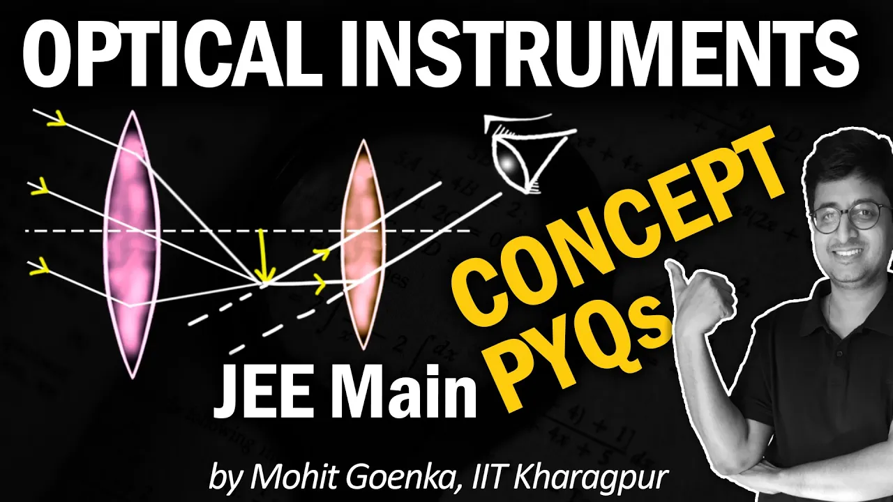

An astronomical telescope consists of two lenses—the objective lens (at the front) and the eyepiece lens (at the viewing end)—aligned so their focal points coincide; the objective creates a real image of a distant object at its focal point, which then acts as a virtual object for the eyepiece, producing a relaxed virtual image at infinity; the angular magnification M equals the ratio of the objective's focal length to the eyepiece's focal length (M = fo/fe), explaining why telescopes require a long focal length objective and short focal length eyepiece.
Astronomical Telescope Ray Diagram and Angular Magnification Derivation
Added:Understanding of refraction and image formation by thin convex lenses, including the thin lens formula.
Basic rules of ray tracing for convex lenses, specifically how parallel rays and rays passing through the optical center behave.
Definition of focal length (fo for objective and fe for eyepiece) and the concept of 'normal adjustment' where the final image is formed at infinity.
Introductory trigonometry and the small-angle approximation (tan θ ≈ θ) used in optical derivations.
Deriving the magnification formula for an astronomical telescope in near-point adjustment (image formed at the least distance of distinct vision).
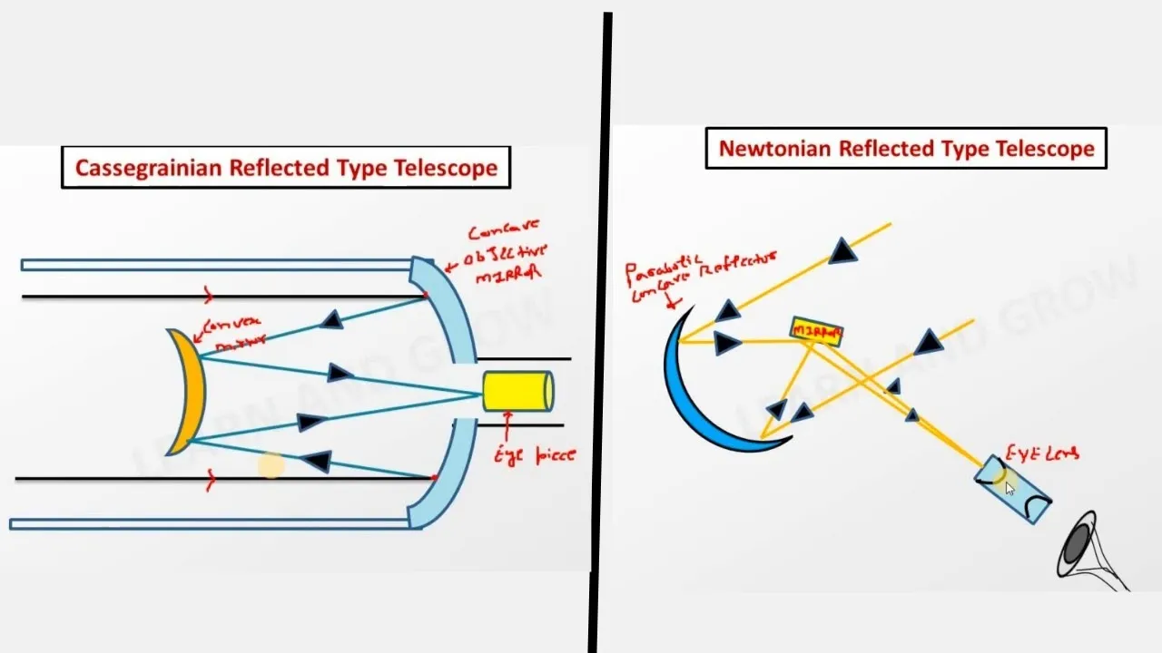
Exploring alternative telescope designs, such as Reflecting Telescopes (Cassegrain and Newtonian) to understand how they overcome chromatic aberration.
Studying the physics of Compound Microscopes and comparing their angular magnification mechanisms with astronomical telescopes.
Analyzing optical limitations such as chromatic and spherical aberrations, alongside performance metrics like resolving power and the Rayleigh criterion.
191.5K views1.6Klikes7:21Original Release: 2014-07-08
this video is about the theory of the astronomical telescope and in particular how to draw good lens Ray diagrams if you're more interested in finding out how an astronomical telescope works then take a look at one of my earlier videos on this subject the astronomical telescope consists of two lenses at the front end of the telescope you have a thin lens known as The Objective and at the opposite end the end you look through you have the eyepiece which generally is a much thicker lens the two lenses are set up in such a way that the focus of both lenses occur at the same point in this case I'm labeling the focal lengths fo for f objective and Fe for f focus of the eyepiece light hitting the objective lens From A Distant object can be treated as though it consists of parallel rays of light now these rays will be focused brought to a focus at a point near the focus of that lens and hence the objective lens creates an image of the distant object at the focus this image now acts like the object like an object for the second lens for the eyepiece now since the object is located at the focus of the eyepiece the image produced by the eyepiece is a virtual image and because it's at the focus the virtual image essentially occurs at an infinite distance from the lens producing a nice easy image relaxing image for the eye to look at to draw lens ray diagram for the astronomical telescope start by drawing a horizontal line across your page which is going to represent the principal axis then draw two vertical lines one on the right hand side to represent your eyepiece and one on the left hand side to represent your objective lens you can also draw in the lenses if you wish although you don't need these for the diagram once you've done this draw point on your principal axis to represent the focus it is conventional with the astronomical telescope for the focus to be Clos to the eyepiece than to the objective lens which gives this telescope positive magnification once you've done that we need to start drawing the Rays of light now any rays of light coming from an object that pass through the center of a lens will continue draw moving in a straight Direction so I'm going to draw a ray of light passing through the center of the objective which hits the eyepiece about just over halfway down now this will create an image located at the focus which touches that ray of light like so now the next stage of my diagram I'm going to draw another ray but this time I'm only going to draw the section passing between the two lenses and I'm going to draw a ray that is parallel to the principal axis the reason for this will become apparent in a moment now this Ray when it hits the objective lens since it's coming from distant object should be parallel to the original Ray so I can now draw in that side of the ray having done that I can now draw a third Ray parallel to to the original two and I know that that Ray should also pass through the tip of the image so I can draw its path between the two lenses like this and you'll see that all three Rays pass through the top of the image like that now the next step in drawing the diagram is I'm going to take this focus and I'm going to draw the same focus on the other side lenses as you will know have two focuses one on either side of the lens in this particular case I've drawn that Focus 6 cm on the left of the lens so I'm going to draw a corresponding one 6 cm to the other side now in order to complete the diagram I can use the fact that this Ray traveling parallel to the principal axis when it emerges from the eyepiece is going to pass through the focus so I can complete its path like that and then we know that when the telescope is in normal adjustment the Rays that emerge from the eyepiece will all travel parallel to each other giving an image at Infinity the final step in the diagram is just to show where the image is located and we can do that by taking each of these rays and just tracing back their apparent path using dotted lines and that is our completed ray diagram Now using our diagram it's possible to figure out one final very important rule for the astronomical telescope that is what the magnification of the of the astronomical telescope is now angular magnification basically is based on how big an object appears to be compared to how big it would be if you didn't look at it using the telescope now if you were looking at it using the uned eye the size of it would be determined by this angle here the angle at which the light from the top and the bottom of the image enters the I'm going to call that Theta o meaning the angle for the object now you can see through symmetry that this angle here Theta o is going to be about the same now using the fact that light going from leaving the top of an object pass would pass through the center of a lens we can see from this line here that the angle at which the image subtends with the I is given by this angle here which is Theta I Theta for the image which is the same as this angle over there now using a little bit of trigonometry if we call the height of the image in between the lenses H and based on the fact that this distance here is the focal length of the objective lens and this distance here is the focal length of the eyepiece to a rough approximation Theta R is going to be about H ided fo whereas Theta I is approximately h / Fe now the angular magnification for the t escope is just given by the ratio of these two quantities Theta i/ Theta o in other words how big the image appears to be compared to how big the object is and this using our relationships is just equal to H over Fe / H over fo we can cancel the two h's and that leaves us with a very simple final equation our angular magnification m is just equal to fo the focal length of the objective lens divided by Fe and from this you can see the reason why the eyepiece needs to have a very small focal length compared to the objective lens
Up Next
9:21
Optics Part 4: Spherical and Chromatic Aberrations Explained
@rogermoore7293
73.2K views•2016-10-25

12:53
21cm Hyperfine Transition in Neutral Hydrogen: Radio Astronomy Basics
@AaronRobertParsons
12.4K views•2011-10-13

32:32
NMR Spin Physics I: Zeeman Effect, Resonance Condition & Larmor Frequency
@nptel-indianinstituteofsci8064
2.3K views•2024-01-17

27:14
Entropy and the Second Law of Thermodynamics Explained
@veritasium
27.5M views•2023-07-01
Related Study Plans & Knowledge Roadmaps
Structured learning paths in Physics
physics
Nuclear Physics (Decay, Fission & Reactors)
01Atomic Structure and the Binding Force
02Radioactive Decay and Half-Life
03Nuclear Fission Mechanics and Chain Reactions
+ 2 more learning modules
12h5 modules
Explore Roadmap
physics
Soft Matter (Polymers, Colloids & Rheology)
01Foundations of Soft Matter & Thermal Forces
02Polymer Physics and Macromolecules
03Colloids, Surfactants, and Self-Assembly
+ 2 more learning modules
38h5 modules
Explore Roadmap
physics
Analytical Mechanics: Lagrangian & Hamiltonian
01Mathematical Foundations: Calculus of Variations
02From Newtonian Mechanics to Constraint Dynamics
03The Principle of Least Action & Lagrangian Mechanics
+ 3 more learning modules
28h6 modules
Explore Roadmap
physics
General Relativity (Spacetime & Cosmology)
01Foundations of Relativity: Special Relativity
02The Geometry of Spacetime: Equivalence Principle & Curvature
03Einstein's Field Equations: The Mathematics of Gravity
+ 2 more learning modules
55h5 modules
Explore Roadmap