



![[VẬT LÝ ĐC - LÝ SINH] BUỔI 5 - 19/11/2025](https://i.ytimg.com/vi/qLV_pQMDuxI/hqdefault.jpg)




![[GEOGRAPHY] Class 7 NCERT | Chapter 2 | हमारी पृथ्वी के अंदर | UPSC CSE 2025 | Apoorva Rajput](https://i.ytimg.com/vi/YnQMz2ABJJU/maxresdefault.jpg)















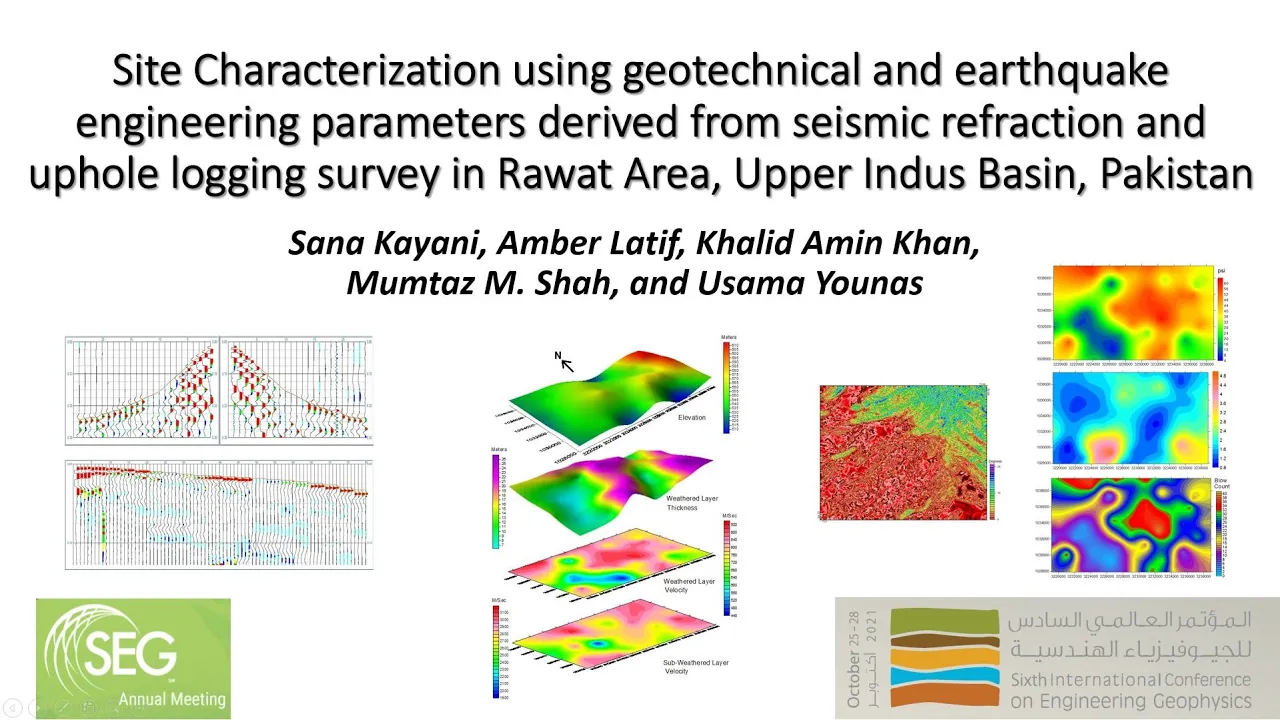

Seismic surveying uses controlled artificial sources to generate elastic waves (P-waves and S-waves) that propagate through subsurface geological layers, with P-waves traveling faster than S-waves due to their compressional nature; the reflection coefficient determines how much energy reflects at geological interfaces based on acoustic impedance contrast, while Snell's law governs refraction angles, and travel time curves for direct, refracted, and reflected waves follow specific mathematical relationships (hyperbolic for reflections, linear for refractions) that enable geophysicists to map subsurface structures and determine layer velocities and thicknesses.
Seismic Surveying Fundamentals: P & S Waves, Reflection, Refraction
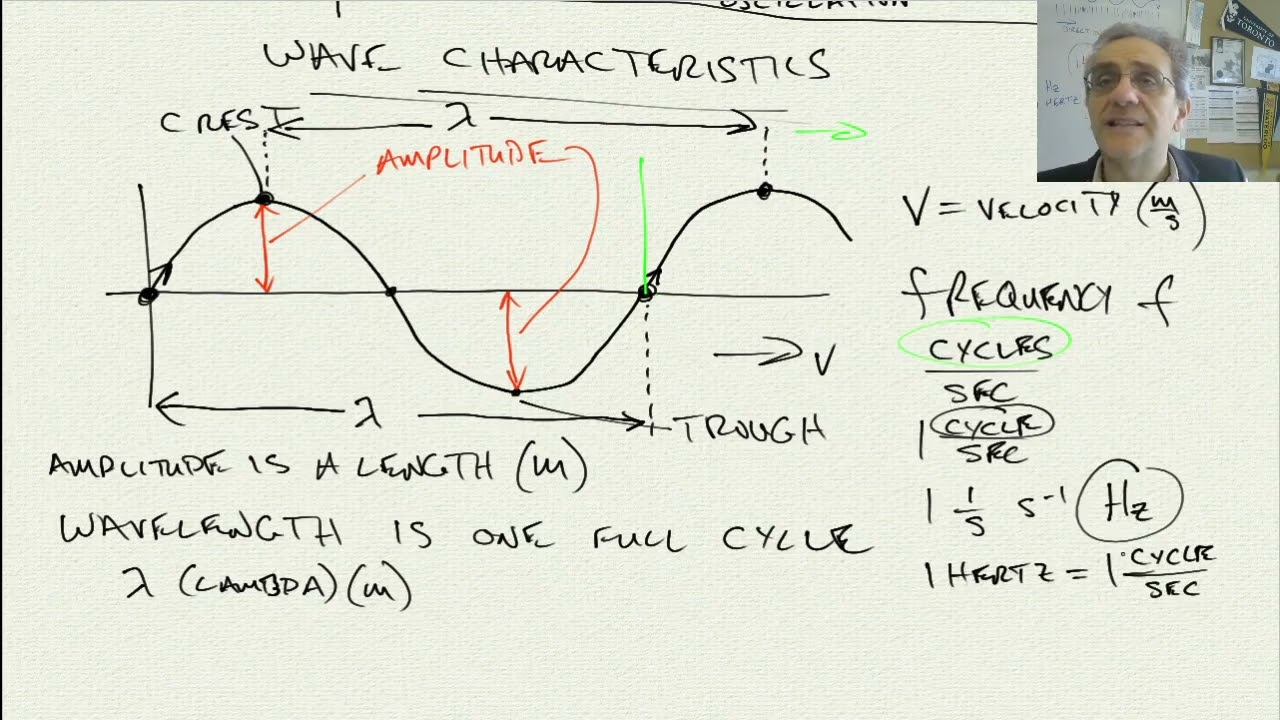
Added:Basic physics of waves, including definitions of wavelength, frequency, velocity, and amplitude.
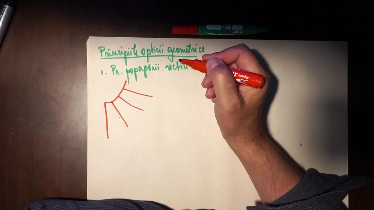
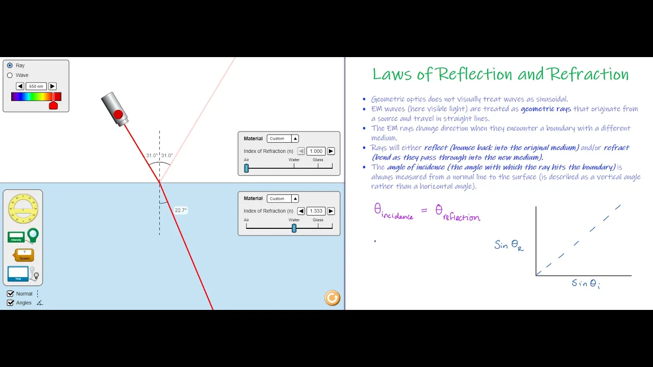
Fundamental principles of geometric optics, specifically the behavior of light refraction and reflection at boundaries.
Introductory knowledge of Earth's internal structure (crust, mantle, core) and the physical states of these layers.
Basic concepts of mechanics and elasticity, particularly how solid materials deform under stress and strain.
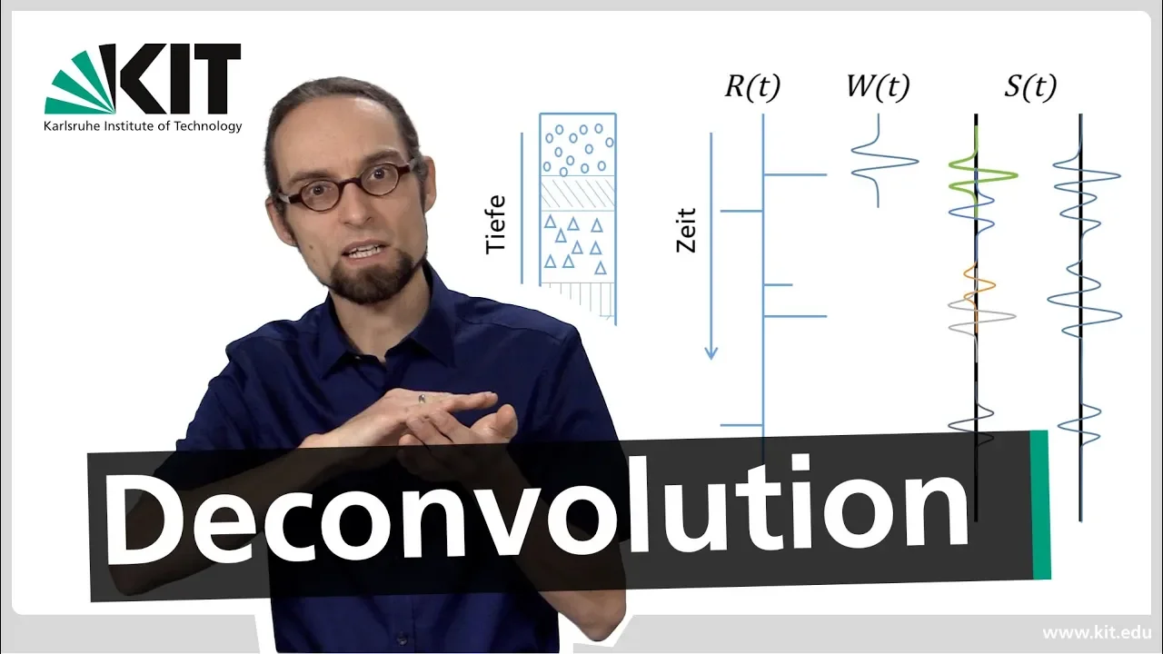
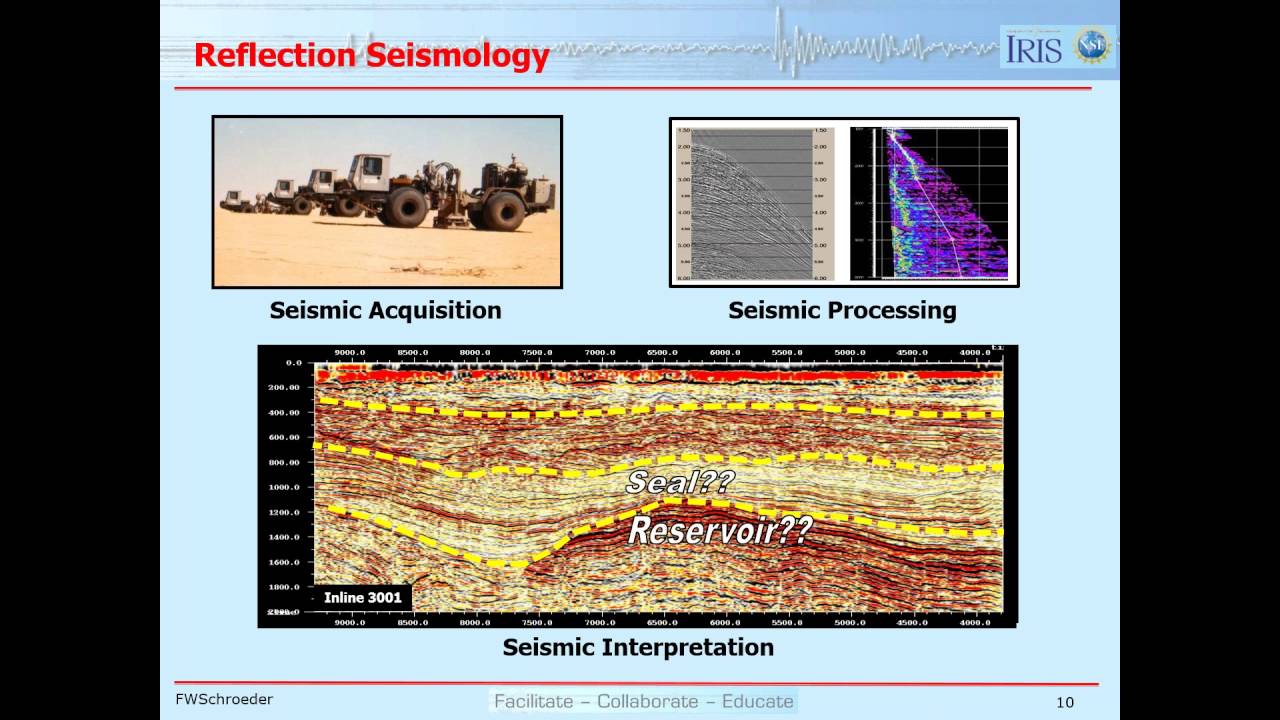
Seismic data acquisition and processing techniques, such as migration, deconvolution, and noise reduction.
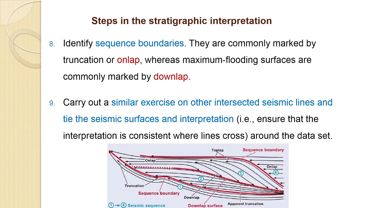
Seismic stratigraphy and structural interpretation to locate natural resources like hydrocarbons and aquifers.
Deep Earth seismology, including the study of global travel-time curves to map the Earth's core-mantle boundary and shadow zones.
Geotechnical and environmental applications, such as using shallow seismic refraction for engineering site characterizations and hazard mitigation.
2.6K views49likes34:09Original Release: 2022-05-23
so hello friends i am now with my new lecture called seismic serving principle and the concept of seismic wave propagation so in this lecture i will be talking about all the concept of the seismic wave and their velocity stressed in elastic moduli and the reflection refraction travel time curves and the coefficients what are the direct waves refracted waves reflected waves equation for the travel time scarves how they travel and what are the different types of seismic sources and the seismic pulse type so i have already discussed about gravity and magnetic survey but in detail now by the request of many viewers i am uploading this uh very detailed survey this is very costly seismic reflection and the refraction survey for oil and gas exploration so before that i will be delivering some basic concepts about it and it is very important topic for the so what are the different kinds of seismic survey and its objectives seismic waves are generally a control source method and propagate through the subsurface and there will be reflection and refraction of the geological boundaries within the subsurface within the subsurface the techniques of the seismic reflection and the refraction seismology they are using artificial and controlled explosions they were developed in search of the oil and the petroleum there the energy pulses are reflected from the subsurface and they are recorded at the near normal incidence and we can actually measure the travel times and that travel times can be converted into the estimates of depth to the interface and there are these receivers to receive the signal from reflection or the refraction to detect the ground survey for marine survey there are receivers that are several kilometers long uh what is the i mean comparison of the with earthquake seismology that earthquake systemology provides information on the gross internal layering of the earth and the measurement of the velocity of the earthquake a specific survey they can provide a clear and detailed picture of the subsurface geology that is on a small scale not a bigger scale and we can and the depth that we can measure from the sesame serving is down to the tens of kilometer using the artificial source method so before proceeding to the seismic survey we need to understand what types of seismic waves can be generated by an earthquake or the manmade source to unravel the structure of the earth's interior okay now seismic surveying there are two types of serving that is reflection and the refraction method and there will be difference between that generally these methods are widely applied to the exploration problems and the mapping of the subsurface for both the methods generally receivers are laid out at a distance along the profile through the short point and that short and receiver distance are small for the reflection survey that distance whereas that for the refraction survey that is very large 10 to 100 kilometer during the crystal survey generally reflection method is widely used in the oil industry for the mapping of sedimentary sequences the reflection systemology is directed primarily at finding the depths to the reflecting surface and the seismic velocities of the subsurface layer reflection seismic data are most utility acquired along profiles that is crossing the geological structure that means we need to take the seismic reflection data uh linearly to the normal to the strike of the structure the major axis of any body that is strike and we need to carry out the seismic reflection survey normal to the stripe of the data okay the energy diffraction is carried out when there is abrupt increase in the velocity with them and which is addressing the crustal thickness and depth to the bedrock when you map the crystal thickness that receivers are laid out far distance 10 to 100 so that is main difference between reflection and the refraction survey for reflection survey we are having reflected wave directory reflected wave apart from the reflected wave all are considered as the noise and they are to be eliminated generally when we use a instead of single hydrophone we use a group of interconnected hydrophone or the geophones for land of the marine survey to eliminate the noise or to reduce the noise to understand different types of seismic waves are propagated through the ground some elementary concepts we need to discuss regarding this so stress and strain relation and hooke's law we can so in your undergrad physics uh experiment if you are doing it you must have i mean read about the stress strain concept when there is external force there will be a balanced internal force and stress is the measure of the intensity of the internal force balance when when we apply stress to the body it undergoes a change in the shape and the size up to a certain limiting value of the stress let me show you a figure that is called yield strength of the material the strain is the linear and within that limit stress is proportional to strength that is called the hooke's law and that is within the reversible limit so we remove the strain and it will be a removal of the stress or vice versa so if our ill strength is exited a certain value in that way in that region our strain becomes non-linear and the irreversible that is called plastic or the ductile strain when you increase the stress further more the body fails by the fracture okay and that religion relationship between the stress and strain in the elastic field uh can be specified by various elastic modulus which is the ratio of the stress to the strain so what type of elastic modulus are there there will be bulk modulus young modulus and the shear modulus so i think in your undergrad physics practical also young modulus experiment you have carried out with a block that will i mean from a thread therapy block and the block will be there will be displacement so from that stress based strain related ratio so let me show you this longitudinal suppose we apply when we ro when we pull a rod or compress there will be a increase in the length or the compression so suppose we pull it by a force longitudinal for force force per unit area that means stress and there will be increase in length l plus delta so young's modulus is defined as longitudinal stress means force per unit area divided by the stress increase in length divided by the original length now in another case we have we have hydrostatic pressure that we apply to the cubic element so pressure is applied from both the sides many sides and there will be compression so accordingly the bulk modulus can be characterized as volume stress divided by the volume strain another thing is the shear modulus so we have a cube a force is applied to it there will be shear stress that force is applied in this direction delta f divided by the cross sectional area a and there will be increase in length so i have shown you that increase in length at delta l by l very interestingly the uh for when you apply that uh that fierce stress to the rigid body there will be no increase in the length so that implies that shear modulus tends to infinity so but in case of fluid there is no resistance to shearing because rigid body offers its full resistance to the shearing that's why the mu tends to infinity but in case of fluid if you physically imagine if we applied shear stress there will be infinite almost increase in the length and that leading to the shear modulus tends to zero that's why shear wave can not pass through fluids that means liquids or gases that elastic constants are generally determining how fast the waves travel through the medium i will tell about what is the body waves this concept let me show tell you about some seismic survival land and here what i have shown tell you the first refraction path this is the generally for reflection this source and the receiver distance are very much far distance way for crystal survey but for the depth to the bedrock it is almost not very much far distance away and this is the reflection path similarly for and this is the second for reflection the rays travel at the greater uh uh second layer at much more time but for uh this is uh this is the seismic survey carried out in ship and the source seismic source where front of the is there uh ray is there so seismic waves is generated and they will travel through different subsurface sedimentary layered sequences there is a c bit in this and the detectors are layout that played out at several distance and many distances there will be a group of hydrophones and from this will cancel the noise and this are shown as the path of the reflected waves at different sequences of the sedimentary layer for oil and gas industry this is for the offshore survey and this seismic is the land survey there's a source of this picture is describing that i want to show you in claims uh let me tell you about the primary and the what are the body waves what are the surface waves actually seismic waves are the elastic strain energy that propagate outward from any seismic source from any seismic source the energy goes out in a equal direction or due to the earthquake or artificial explosion and their velocity are determined by the elastic modulus that means k mu and rho two is the travels that i have described and there are two groups of seismic waves how will determine body waves if the waves that will travel through the earth interior that is called the bodies there are primary and the shearers for the body waste primary means compressional waves and if the earth move along the surface that means they are surface waves generally body waves the one of the bodies are compressional waves that means longitudinal the primary waves that propagate by compressional and the dilatational strains what is the example sound wave that means direction of propagation is a perpendicular particle vibration is part parallel to the direction of the propagation that is the sound wave and during my electromagnetic lecture i have discussed and show visual figures of the light that is the shear wave they propagate by the shear strain which is in the direction perpendicular to the direction of the wave travel example is just a lightweight hour this is a surface wave and this is a body wave so after that move along the surface after the explosion on the earthquake and the body wave move up that means travel to the body of the weight generally it is a very important point seismic surveying used only computational waves because seismic detectors recording only the ground vertical motion and that are sensitive to the horizontal motion of the a s wave they are insensitive so for if we record s waves and surface wave they gives greater information about the subsurface okay but that will be at a cost of greater data acquisition so it is very important point what is the velocity of the p and s waves any velocity is determined by the root over of the elastic modulus divided by the density of the material so in case of body waves the velocity will be k plus 4 by 3 mu this equation and for surface wave the velocity is root over mu by rho means the shear strength all other and rho is the density through his the travel now that we can see the compressional waves uh have greater velocity than the shear wave in the same medium that means if density remains same we know fluids have do not have any shear strength so shear oil cannot pass through liquids fluids air water and earth's outer core that are fluids and if the rock becomes more and more compact that means the elastic modulus that k and mu increases and they increases more than the density so the ratio will increase that that ratio will be increasing more and more and if we decrease porosity that will also lead to the increase in the velocity of the compression on the shear waves when there is a seismic wave uh there is a change from liquid state uh to the solid state the speed up of seismic waste will be there uh due to that increase in the shear because in liquids ah because shearer cannot pass through liquid so mu will be zero but for solid medium then we will be more and if we know the velocity of p waves is higher so they always reach a detector before any s waves and so they are easier to recognize so most seismic surveyings generally use compression always because of their higher velocity and the ground motion that have already uh described a vertical motion for many arts material that veloci these are all observation from the semi-wave velocity what are the factors that are controlling the wave velocity and how the with medium that is velocity is changing increasing or decreasing for many arts material the surface wave velocity is uh sixty percent of the primary velocity the value of velocity is ninety percent of the surface wave velocity so the value of velocity is lesser than primary or the shear waves value of velocity is approximately half of the primary wave that vr is the value that is surface wave i will show you the particle motion in the compression on the shear wave i think in in my lecture through electromagnetism that i mean light wave the particle motion is perpendicular to the direction of the propagation so that is from for the shear wave let me show you a compressional wave if there is a direction of propagation in this direction and particle motion also in the same parallel to the direction of propagation example is the sound wave and how the wave travels with travels by series of compression and the dilatation compression that is compressed in this direction and the dilatation you can see easily pictorially for shear wave there is a shear that is shear vertical wave that is shear horizontal wave if there is a direction of propagation in this direction in the same so the particle motion is perpendicular to the direction of propagation this here vertical wave and shear horizontally it is in that direction there are two types of shear waves so generally you can see there is a direction of propagation in the x direction if you can assume this is x the particle movement will be along y perpendicular so you can see direction of propagation for compressional waves that is compression travels through this is the region of compression the density of the dots that will be defining and the where there is a real there is a rarefaction this region and there is a compression so that so in that way the compressional wave travel but for the sheer wave we can see that the motion of the particles in the rod that are perpendicular to the direction of the propagation in this direction this arrows are defining so i hope you have already visualized this how the direction of propagation is related to the particle motion for both compressional and the shear wave and in case of surface wave that is a retrograde elliptical particle motion for the value as we can see and for the long waves the particle motion and in and out of the face generally they are comparable with this uh shear horizontal motion and for rally waves this the direction of propagation is same in the direction and the particle motion is in that elliptical motion okay now as i am repeatedly talking about the seismic waves so let me give some glimpse about the waves and the wavefronts seismic waves generally propagate outward from the seismic source which is with the velocity that will be determined by the physical properties of the wave the wavefront is the locus of all points that the pulse reach at a particular time suppose the pulse is traveling through homogeneous way so the velocity will be same in all direction that means it is called isotropic nature and away from the source so that at any subsequent time of the wavefront the at any subsequent time the wavefront will be that i mean sphere so this is the wavefront ideal case uh the pulse is reaching at a pulse is traveling at equal velocity in all direction so a front will be perfect sphere but in ideal case is always not uh applicable when there is a wave front of the p wave so there will be change in velocity or any wave so in the many segments the wave will be speed up and in many segments the wave will be bending speed down so bending in this bending will be there and there will be resulting in the distortion from the perfect sphere so let me show you this is a source and that's a p waves is travelling a different direction with the velocity will be changing is not same in all direction so the perfect sphere will be distorted and you can see the rays are perpendicular to the the ray paths that are always perpendicular to the wave front there's a p-wave wave front so source i have mentioned how you can also read from that but you have a preliminary knowledge about the waves and the wave front before proceeding to the seismic serving now you have i think this is also very important point reflection and refraction and when there is a at an interface between two rear uh rock layer the energy of the seismic pulse is just divided into reflected in the transmitted rate the reflection the amount of energy that is reflected is determined by the contrast in the acoustic impedance what is the acoustic impedance this term is the multiplication of the density and the velocity more the energy is reflected the greater is the contrast in the acoustic impedance you can see the reflection coefficient it is the ratio of the amplitude of the reflected wave to the incident wave and for a normally reflected ray we can incidentally we can determine the reflection coefficient will be the contrast in the acoustic impedance z2 minus z1 divided by z2 plus z1 so if there is no acoustic impedance contrast set 2 is equal to z1 the reflection will be 0 that means coefficient so there will be no waves will be reflected if there is no contrast in the acoustic impedance along a surface and the transmission coefficient is divided as the ratio of the transmitted to the amplitude of the incident ray so if generally for a surface interface the reflection coefficient is limited within the 0.5 and plus or minus is determined by this density it is going from lower density a higher dense this product is less than this here that will be negative and they are typically much less than 0.2 so normally the bulk of the seismic energy is transmitted and only a field proportion is impedance so now we show victoria the reflection the reflection of the reflect uh oblique ray and with the snail's law i think uh you can determine when there is a incident wave suppose p wave it is incident uh on an interface it is having a acoustic impedance there will be reflected and the transmitted p wave and some compressional energy is also converted into the reflected and the transmitted ace waves but that are polarized in a vertical plane in another day i will tell you about the concepts of polarization that is so this is one medium that is reflex z1 is the acoustic impedance 01 v1 so there will be acoustic impedance contrast accordingly the waves will be reflected and there will be diffracted p wave and refracted s waves so there is an empirical relationship with the source with the reflection reflect coefficient associated with the velocity of the two layers from which the rays are reflected and you can see for the theta theta one angle there will be angle of incidence theta one will be angle of reflection from the sense law because for the reflection that v one will be v two so sine theta one will be sine theta two so theta one is equal to theta two and reflect address there will be angle of uh refraction theta two uh so if from the sales law you can tell that if the velocity of the second layer is greater than v1 the ray is reflected away from the normal in this direction so because the theta 2 will be greater than theta 1 s for the velocity and if it is going from lower velocity higher velocity at the lower velocity layer so accordingly theta 2 will be lesser and the waves will be coming towards this normal in that way there is a snail relation we can determine the rays are reflected away or close to the normal to the interface suppose now i will tell you the reflection so what happens for a single layer interface there there will be source of energy waves will be reflected and there will be from this this travel time from for the reflected error from uh source to the receiver x is the offset distance means distance from the source to receiver now that is the travel time so i will urge everyone to determine this travel time how will determine this total travel time for reflection but let me show you and this this is the source of energies there so rays will be reflected from a source of energy and detectors are placed at a certain distance from each other so as per the acoustic impedance contrast the layers will be reflected in a single interface here from this equation if we can tell that if the distance between short receiver is zero so the time will be t0 so that will be 2z by v for a reflected ray you can see that time that travel time this is the equation for the travel time you can see this equation is the equation for the hyperbola and according to that equation this is a source to receiver and there will be a vertical distance depth or travel time curve so in that this is the near source to receiver distance and as you move away x will be greater than greater source to receiver distance for your convenience let me show you one under a path through which you can determine the travel time so travel time will be determined by the length l1 plus l2 total travel distance divided by the velocity so we do it with our own to come to this equation so and that is for the that equation is the near surface incidence t 0 that means vertical reflection to z dot 2 h by divided by the velocity v 1 yes it is a h distance so for reflection service the source uh vertical uh reflection almost source is near to the receiver is very near to the source so this curve is the travel time curve for the reflection now in case of direct and critically refracted waves what are the travel times curves so what is the direct wave let me show you the figure yes so when there is a source so waves are directly without any reflection where waves are directly reaching the detector so this is the distance from source to receiver and so the travel time tg is equal to x by velocity the upper surface velocity so from this slope we can determine the velocity for the direct wave to reach from the source to receiver for the body wave now we'll tell our another important thing that is critically reflected arrival when we are having velocities higher in the underlying layout there is a particular angle of incidence that is this angle of incidence for this there are many angle of incidence for if the velocity is higher for a particular angle of incidence the angle of refraction will be 90 degree and that is called critically refracted ray for which the wave travels along the interface at a very high velocity means second p2 so what we can see from the snail's law the angle of incidence is the theta c for particular angle of incidence angle of refraction is 90 degree so from that relation we can determine the critically reflected angle sine inverse v 1 by v and now uh let me show you the travel time curves for the critically refracted in the from the source the there will be ray and for critically reflected trait the angle of diffraction will be 90 degrees so waves will be traveling at the higher velocity layer more time and and this is the travel time curve for the critically refracted rays so how from the equation we get it let me show you so suppose there is three layers are there for each segment suppose from this segment the time travels distance divided by the velocity so from 41 the distance is h by cos theta c divided by the velocity for this segment that time spent is t2 so what is the distance that is x total uh source to receiver distance minus this distance that is that is we have to omit this distance is 10 that means 2h tan theta c so we will get this distance and then what is the velocity v2 and for this segment also t1 is equal to t3 now total travel time is you have to sum up after summing up we can reach to this equation now we have to apply snell's law sine theta c divided by the cos theta c because sine theta c is equal to v 1 by v 2 i have already shown for critically refracted rays using the snell's law the angle of refraction will be 90 degree so from that we'll reach to this equation that is sine theta c that is also sine theta is sine square theta c 1 minus sine square theta c means cos square theta c so after that we will reach to the equation of total travel time is equal to this term that term is a t axis intercept we can define it as a d one just like in reflection there is one term called t zero near surface vertical reflection that is t1 and there will be x by v2 so this is a straight line equation with the intercept is t1 and the slopes will be increasing in that direction but slope will be 1 by 2 that means 1 by velocity of the upper layer okay so this is the travel time curve formula for the critically refracted rays now if we want to compare between the critical time curve the direct race critically reflected trace we have to draw a picture so from this picture you can see theta c angle that is reflex reflect that is angle of incidence for critically refracted trace and that is direct that is a direct ray and there will be reflected rays with the angle of reflection is theta 1 and that travel time if we plot the travel time curve we can see there will be t axis intercept for the critically uh that means refracted trace and one by v2 is the slope but for the direct wave that slope is one by v one so that means direct wave is very sharp and velocity does velocity is less so that slope will be greater many times better than this slope for the reflected rays so for the refracted rays that values 1 by v2 is very much of less steep than the direct waves and there is a rectangular hyperbola that is the hyperbola curve for the uh that means reflect address this curve so we can see at the greater of i mean at the greater offset this offset there is a so there is a distance called xcr so this is the distance is called crossover distance beyond which the critically reflected waves that arrives before the direct waves so before that uh near to the source the reflected waves arrives after the direct waves that means travel time is greater but beyond this distance the reflected waves is uh arriving at a less time to the before the direct waves so and that distance is determined by the velocity and that distance or the thickness for the layer for the two layer model so and there is another distance called xc which is the closest distance from the source that source from is the clinically refracted ray we can observe again i am just recapitulating the travel time curve for the direct wave that is x by v 1 the travel time curve for the refracted waves that is there is a t axis intercept and x by v 2 and for the reflected rays it is a hyperbola that means root 2 is root over of the t 0 square plus x square by v 1 square but t 0 is the near vertical reflection that means two-way travel and two-way travel time this distance divided by the velocity and where t1 is equal to that 2h cos theta c by v1 so i hope from the picture and the travel time relationship you can easily understand in a in a i mean practically when you are carrying out this reflection or the refraction survey what type of waves you can assume in a reflection survey and based on the that travel time curve for the reflected and the direct wave you can omit that reflected and the direct waves in case of reflection survey follows that reflected and direct waves are considered as a noise so the source is there i have already mentioned this you can get these curves now uh let me come very briefly to the seismic source and the seismic pulse type for seismic survey so there are the explosive sources and there are explosive sources so they are on the land and generally detonated in shallow short holes to improve the coupling there will be minimum phase pulse that means burst of energy near the time of the event and there will be reverberation which diminishes with time that means the examples are the dynamite and in the land and ergon at the sea and there are also non-explosive land sources there's a fibrosis is the most common example for the reflection survey there it uses a truck mounting vibro vibrators to pass into the ground and an extended vibration of low amplitude and continuously varying frequency that is called the sweep signal uh then the pulse type will be zero phase pulse that is the zero phase pulse so there will be equal amplitude between the negative and the positive t axis so uh generally instead of abrupt exploration that means for the g or zero phase pulse the vibration can be sent into the ground as a sweep of continuously varying frequency there is also minimum phase pulse so generally in a reflection survey we use the minimum phase pulse instead of the zero phase pulse that is the minimum phase pulse is there positive is the positive amplitude is marked as a colored black and this is the negative amplitude okay so this type of sources are generally required for the seismic survey so in detail i'll be describing when i will tell in my next lecture about the details of seismic surveying reflection surveying method what are the procedures for the data and the noise reduction in the seismic reflection method particularly okay so this is the reference that i have already mentioned in my book i'm in my presentation from that reference i have taken uh i will just request to you if you like my lecture please share it like it follow it and comment on it if you had any doubt and also turn on the bell notification icon so this is my channel name and this in this channel i am delivering lecture for the upsc preparation beta physics beta geophysics and in the next lecture i will be presenting with all the seismic reflection method principle and the procedures of that data acquisition noise elimination and also maybe with practical cases for the seismic reflection hope you have liked it thank you very much for your patience
Up Next

34:26
Seismic Reflection Principles in Geophysical Interpretation
@IRISEarthquakeScience
39.8K views•2017-07-11

12:53
21cm Hyperfine Transition in Neutral Hydrogen: Radio Astronomy Basics
@AaronRobertParsons
12.4K views•2011-10-13

32:32
NMR Spin Physics I: Zeeman Effect, Resonance Condition & Larmor Frequency
@nptel-indianinstituteofsci8064
2.3K views•2024-01-17

27:14
Entropy and the Second Law of Thermodynamics Explained
@veritasium
27.5M views•2023-07-01
Related Study Plans & Knowledge Roadmaps
Structured learning paths in Physics
physics
Nuclear Physics (Decay, Fission & Reactors)
01Atomic Structure and the Binding Force
02Radioactive Decay and Half-Life
03Nuclear Fission Mechanics and Chain Reactions
+ 2 more learning modules
12h5 modules
Explore Roadmap
physics
Soft Matter (Polymers, Colloids & Rheology)
01Foundations of Soft Matter & Thermal Forces
02Polymer Physics and Macromolecules
03Colloids, Surfactants, and Self-Assembly
+ 2 more learning modules
38h5 modules
Explore Roadmap
physics
Analytical Mechanics: Lagrangian & Hamiltonian
01Mathematical Foundations: Calculus of Variations
02From Newtonian Mechanics to Constraint Dynamics
03The Principle of Least Action & Lagrangian Mechanics
+ 3 more learning modules
28h6 modules
Explore Roadmap
physics
General Relativity (Spacetime & Cosmology)
01Foundations of Relativity: Special Relativity
02The Geometry of Spacetime: Equivalence Principle & Curvature
03Einstein's Field Equations: The Mathematics of Gravity
+ 2 more learning modules
55h5 modules
Explore Roadmap