


















![✔ Заставим говорить Taranis(Horus) по-человечески! Низкий заряд, RSSI и тд [Предупреждения в OpenTX]](https://i.ytimg.com/vi_webp/75WsQollzyw/maxresdefault.webp)


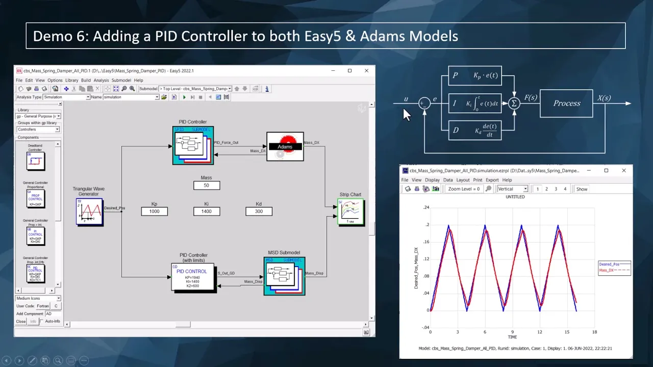
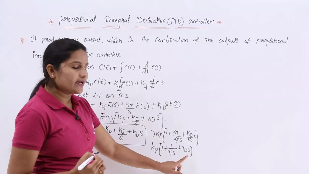
A 250 Hz flight controller control loop for quadcopters uses PID (Proportional-Integral-Derivative) control to stabilize rotation rates by calculating error between desired and measured rates, with the P term responding to current error, I term accumulating past errors to prevent steady-state error, and D term predicting future error based on rate of change; the loop runs every 4 milliseconds, limiting throttle to 1800 microseconds (80%) to reserve power for stabilization, maintaining minimum 1180 microseconds to prevent motor shutdown mid-flight, and using a 400 microsecond integral windup limit to prevent overshoot when the quadcopter cannot achieve the desired setpoint.
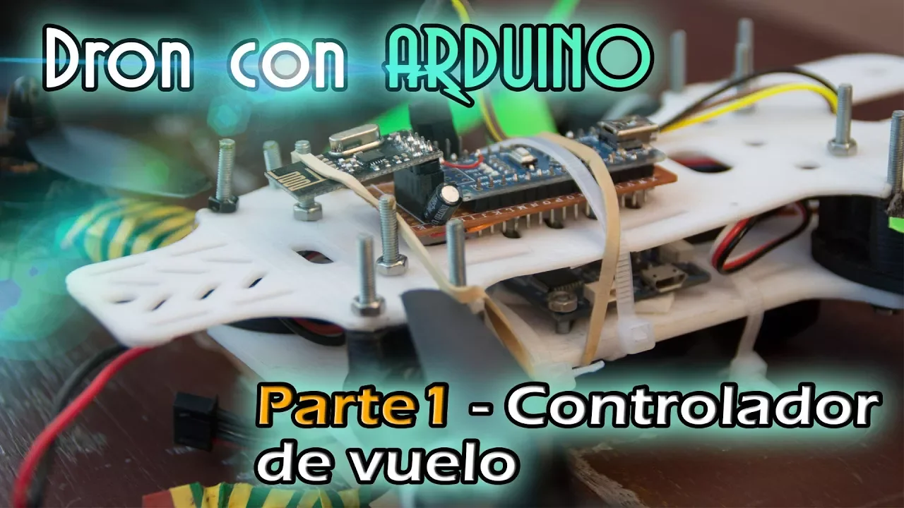
Arduino-Based Quadcopter Flight Controller: 170-Line Code Explained
Added:Basic proficiency in C/C++ programming and the Arduino IDE, including working with registers, interrupts, and basic functions.
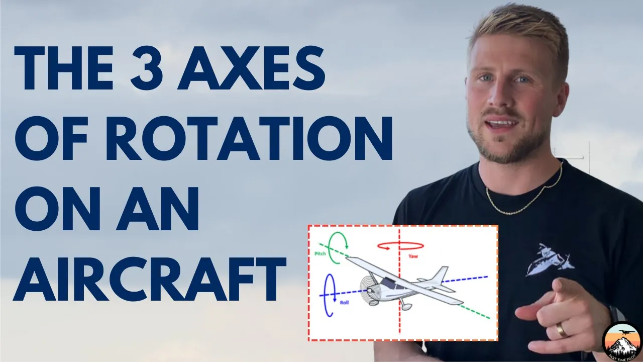
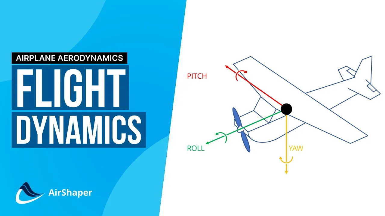
Fundamental physics of flight dynamics, specifically understanding the axes of rotation: pitch, roll, and yaw.
Basic electronics and hardware knowledge, including how Pulse Width Modulation (PWM) is used to communicate with Electronic Speed Controllers (ESCs).
Conceptual understanding of feedback control systems, particularly the basic purpose of a Proportional-Integral-Derivative (PID) controller.
Implementing sensor fusion algorithms, such as Complementary or Kalman filters, to combine accelerometer and gyroscope data for more accurate orientation estimates.
Advanced PID tuning techniques, including manual tuning strategies and frequency response analysis to handle external disturbances like wind.
Integrating fail-safes and telemetry, such as low-battery auto-landing, loss-of-signal detection, and real-time wireless data logging.
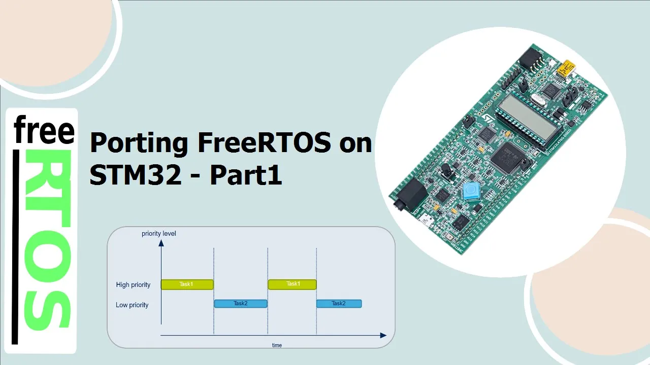
Porting the flight controller to high-performance 32-bit microcontrollers (e.g., STM32, ESP32) and exploring RTOS (Real-Time Operating Systems) for multi-threaded flight tasks.
39.3K views667likes8:02Original Release: 2022-10-05
after a lot of hard work you now have all the ingredients to create your first flight controller and test it on your quadcopter first it is important to make sure there are no short circuits on your quadcopter frame when this is not the case you start testing the motor separately without the microcontroller in between this can be done fairly simply instead of connecting the receiver to the frame connect the ESC directly to channel 3 of the receiver through the female jumper wires this way you can control one motor directly from the receiver just make sure you put your radio transmitter to pwm instead of PPM when you have successfully rerouted the ESC cable connect the battery the ESC should make some noises indicating that it receives power move the throttle stick of your radio transmitter upwards for the motor to start repeat it procedure for all four Motors to verify that they work correctly and that the rotation directions are correct as well now let's start programming your first flight controller I will put the full code on GitHub such that you can easily explore and further adapt it the flight controller code starts with the definition of the gyroscope receiver and power switch variables which you already saw in Parts 4 5 7 and 9 as the parameter that will keep track of time during each control Loop Now define the variables necessary for the PID control Loop remember that each PID control Loop contains three variables and three constants the PID control Loop will result in three variables that are initialized as being zero Now define the p i and D constants for the roll pitch and your rotation rates as seen in the previous video declare the motor input variables as well now create the functions for monitoring the battery level and the receiver inputs continue with the function that will extract the rotation rates from the gyroscope the no PID function will contain the PID equation that was constructed in the previous video first the P term is calculated subsequently the I term and finally also the D term remember that we will create a 250 Hertz Loop meaning that the length of one iteration is equal to 4 milliseconds to avoid integral windup limit the value of the item and PID output to 400 microseconds integral windup is a phenomena in which the integral term accumulates a significant error due to saturation and causes a large overshoot for example when the quadcopter cannot achieve the desired set point because it did not yet lift off the ground at the end of the function you need to return three outputs the PID output itself which will be an input for the motor and the current error and integral term that will be stored for the next iteration also create a function that resets these variables for random Motors are for example turned off now start the setup phase by Illuminating the red LED start the communication with the gyroscope and continue with its calibration during this period you should not touch the quadcopter to avoid messing up the calibration set the pwm frequency of the motor output pins and the resolution illuminates the green led to show that the setup process is finished and determine the initial battery level just before exiting the setup process you need to check that a throttle stick is in its lowest position otherwise if you accidentally left the throttle stick in a higher position and the radio transmitter is not nearby the motors could suddenly start off after the setup process Without You controlling it with these lines you stay in an infinite Loop until you move the throttle stick between 1020 and 1050 microseconds so moving it from the lowest position to a slightly higher position in the last line of the setup process start a timer that will count the time in the control Loop start the control loop with the corrected rotation rate measurements read the commands sent to the receiver and convert them to the desired rotation weights as seen in part 11. now calculate the error between the desired and the measured rotation rates call the PID function to execute the PID calculations remember that each PID function contains six variables the output of each function will be a part of the motor input and the error variables that need to be passed to the next iteration with the throttle stick you are able to go to 2000 micro seconds which would give maximal power to all four Motors however this would give no room to stabilize the rule which and your rates that is why you limit the throttle values to 1 800 microseconds or 80 percent now calculate the motor inputs with the quadcopter Dynamics equations you saw in part 11 remember to convert the throttle values in microseconds to their 12-bit equivalent by multiplying them with 1.024 make sure that the inputs to the motors do not exceed 2000 microseconds after the dynamic equations to avoid overloading them to avoid stopping the motors in mid-flight keep them turning at 18 when the motor input decreases below 1180 microseconds the previous lines would mean you can never switch off the motors as they keep turning at minimally 18 power just before sending these commands to the motors you add the condition that if the throttle stick is brought to its lowest position so below 1050 microseconds all four motor stop usually you would do this after landing the quadcopter the PID parameters need to be reset in case you want to have a bumpless restart now you are finally ready to send the commands to each of the four Motors keep track of the battery level with these lines of code and illuminate the red LED if necessary the last step in the iteration is to wait until the 4000 microseconds or 4 milliseconds have passed using a while loop when this condition is met we set the timer to the actual time and the program can proceed to the next iteration congratulations you just created a 250 Hertz control Loop to upload the code connect the TNC with your computer when the code is uploaded the red LED should illuminate first from this point do not move the quadcopter to avoid interfering with the gyro calibration when the calibration is finished the green LED will be illuminated you can now start the motors by moving the throttle stick softly up and down after the beeps of the ESC also the quadcopter firmly with one hand and increase the throttle to test the flight controller for your first flight make sure you start outside at a large grass field without any people nearby to minimize any damage to the quadcopter or others in the event of a crash for the next video 0 we will have a more detailed look into the physical components necessary to build the quadcopter don't forget to subscribe for this Channel and see you next time
Up Next
38:03
Exploring Ardupilot: An FPV Pilot's First Pixhawk Build
@JoshuaBardwell
190.8K views•2023-11-21

58:25
MathWorks Virtual RoboSub Simulation Environment | Webinar 2026
@RoboNationInc
209 views•2026-03-10

11:04
How to Build a Self-Balancing Robot: Arduino Nano & MPU6050
@easytechzones
16.8K views•2022-03-09

25:22
Micromouse: The Fastest Maze-Solving Robots on Earth
@veritasium
23.5M views•2023-05-24
Related Study Plans & Knowledge Roadmaps
Structured learning paths in Robotics
robotics
Building Delta Robots: Kinematics & Pico
01Foundations of Delta Robots & Mechanical Design
02Electronics and Microcontroller Setup with Pi Pico
03Delta Robot Kinematics and Coordinate Math
+ 3 more learning modules
65h6 modules
Explore Roadmap
robotics
Building Ballbots: Dynamics, Kalman & LQR
01Embedded Electronics & Omniwheel Actuation
02Ballbot Kinematics & Rigid Body Dynamics
03IMU Sensors & Kalman Filter State Estimation
+ 2 more learning modules
42h5 modules
Explore Roadmap
robotics
Micromouse: Hardware, PID Control & Flood-Fill
01Electronics & Teensy Microcontroller Basics
02Sensors and Actuators: Motors, Encoders & IR
03Precision Movement: Implementing PID Control
+ 2 more learning modules
35h5 modules
Explore Roadmap
robotics
CDPR: Kinematics, Arduino & Winch Control
01Foundations of Arduino & Basic Electronics
02Stepper Motors and Winch Mechanics
03Kinematics of 2D Cable-Driven Robots
+ 2 more learning modules
28h5 modules
Explore Roadmap