





















X-ray diffraction (XRD) is a powerful analytical technique that uses Bragg's Law (nλ = 2d sinθ) to determine crystal structure, phase composition, crystallite size, and microstrain by measuring the constructive interference of X-rays diffracted by atomic planes in a material; the technique requires specialized equipment including an X-ray tube source, sample mount, and detector with primary and secondary optics to condition the X-ray beam, and relies on analyzing diffraction patterns where peak positions reveal lattice parameters and peak intensities indicate elemental composition.
X-Ray Diffraction (XRD) Explained: Bragg's Law & Setup
Added:Basic concepts of crystallography, including crystal lattices, unit cells, and Miller indices.
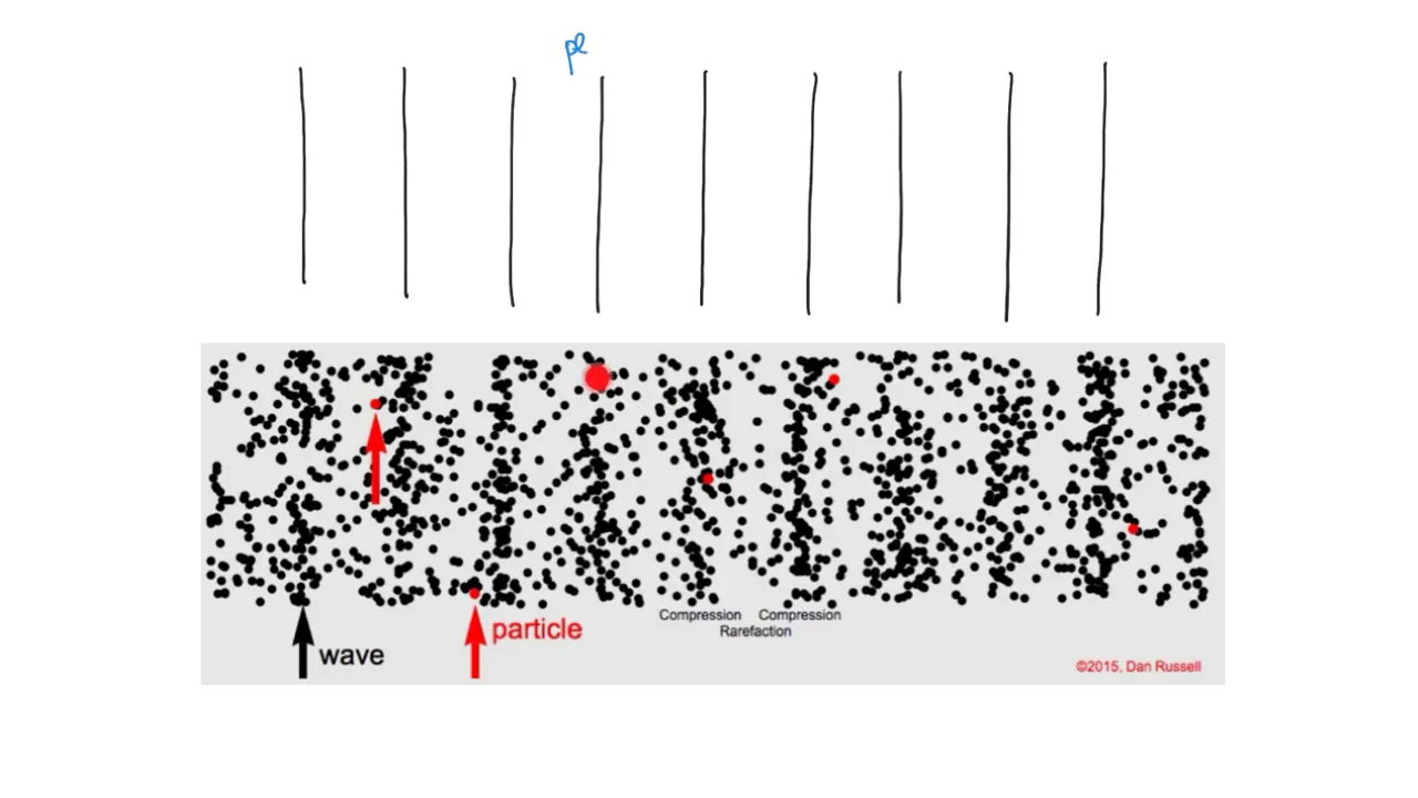
Wave mechanics, specifically the principles of constructive and destructive wave interference.
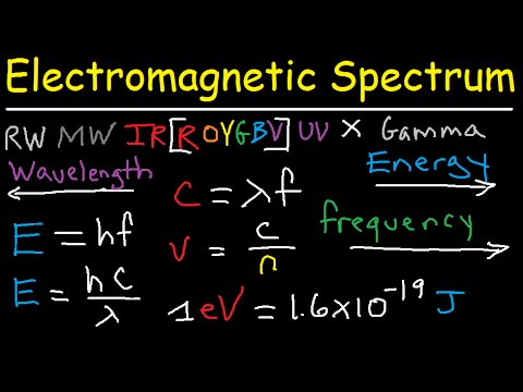
The properties of the electromagnetic spectrum, particularly why X-ray wavelengths correspond to atomic spacing.
Fundamental geometry and trigonometry required to calculate path differences and derive simple wave equations.
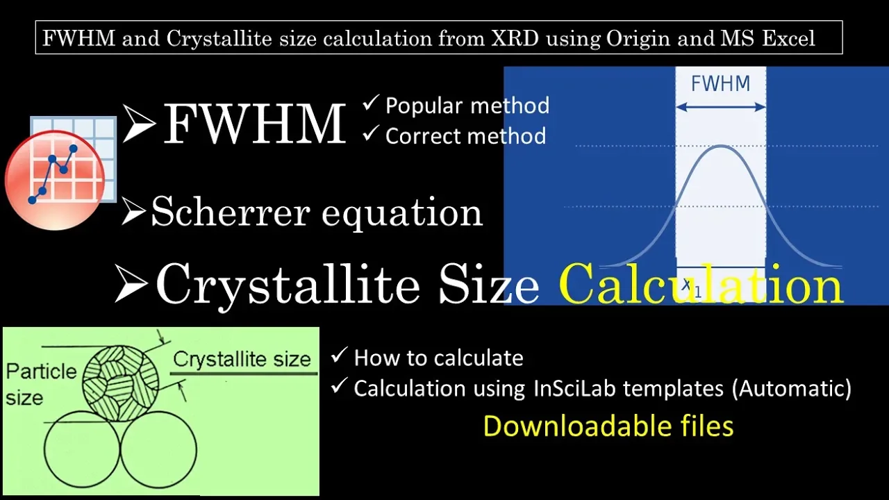
Applying the Scherrer Equation to estimate crystallite size and microstrain from diffraction peak broadening.
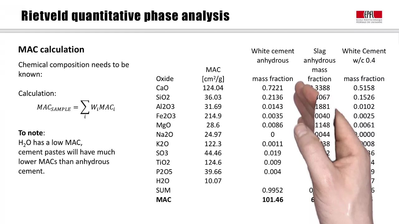
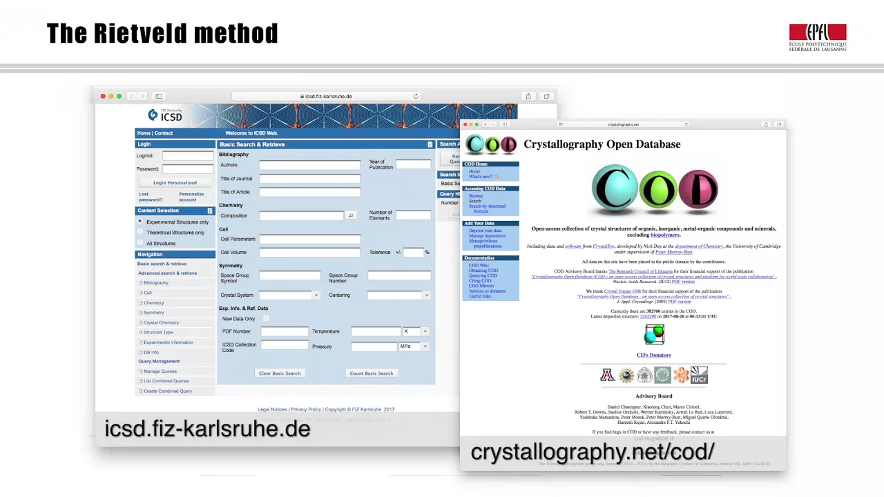
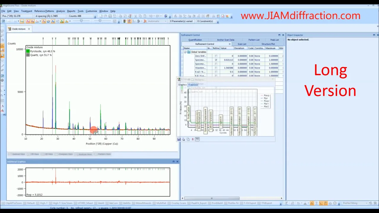
Utilizing Rietveld refinement and phase-matching databases (like the ICDD) for quantitative phase analysis.
Comparing the experimental setups and applications of Powder XRD versus Single-Crystal XRD.
Exploring advanced structural characterization techniques, such as Neutron Diffraction and Electron Backscatter Diffraction (EBSD).
111.3K views1.2Klikes15:14Original Release: 2017-01-13
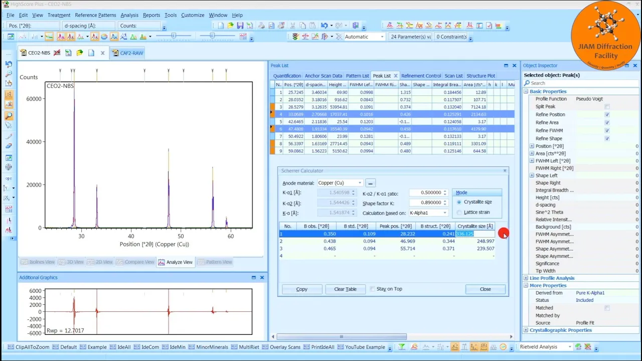
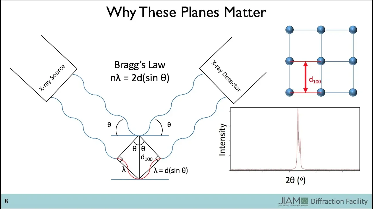
hello my name is Emily crawl and this is a training video to give you background information on x-ray defraction so what do x-ray defraction machines do these machines are incredibly powerful and can be employed to run many different types of analysis some of the most common uses for xrd machines include analyzing the crystal structure and even performing quantitative analysis of phase composition it is used for finding the crystalite size and micro strain but it can also look at the strain on a macro scale known as residual strain xrd can identify defects and samples it's used to identify and characterize polymorphs texture orientation can be found and unit cell lattice parameters and bravis lattice symmetry can also be analyzed not only can it be employed to analyze crystalline materials but it's also frequently used for its ability to identify amorphous materials x-ray defraction is extensively used in material characterization in material characterization it's necessary to identify both the elements present as well as the structure in order to fully Define the material unlike other characterization methods xrd can provide information on the elements as well as their structure which is defined by the atomic Arrangement a material composed of only one element is called an allat trophy and this can be a polymorph a polymorph is a material with the same composition but different structure the best example I can come up with is carbon carbon can either form graphite or diamond or even an amorphous structure depending on its crystallin form so in the case of carbon it's extremely important to not only identify the element carbon is present but also the structure that it takes to understand what material you're working with so how does xrd actually do this the best place to start is Bragg's law brags law is used in defining a material using x-rays which have very short wavelengths on the scale of an angstrom and these are aimed at the sample when the x-rays hit the atoms in the sample the path of the x-rays is altered in 1912 WL brag discovered the relationship between the wavelength of an x-ray and the angle of defraction and the distance between the Turtle planes of a crystal and this is Bragg's law the wavelength is Den noted with Lambda and is proportional by an integer n to two times the spacing between the planes D which is multiplied by the sign of the defraction angle Theta the Fred x-rays interact with each other and can either have a constructive or destructive interference destructive interference occurs when the waves are out of phase meaning that the peak of one wave coincides with the peak of an opposite amude in the other wave essentially the two waves cancel each other out on the other hand constructive interference occurs when the waves are in Phase meaning that the positive peaks of the two waves are aligned and the waves are Amplified whether or not the x-rays will be constructive during xrd is determined by the material properties of the sample and the angle at which x-rays are applied and detected now that we know how brags Law relates the defraction angle and the lattice spacing we can take a look at how xrd machine to use this law first we need to identify the basic setup of the machine it includes three main parts the X-ray tube the sample Mount and the detector in order to find the lce spacing using brags law a rotation must take place so that the x-rays can be detected at various defraction angles in any xrd machine there'll be two or two of the three main parts that will rotate for many machines the source is fixed with the sample and detector rotating but for others the XR machine has a fixed sample Mount while the X-ray tube and the detector rotate about it an obvious advantage to having a fixed sample Mount is that the samples are liable to slip off the stage of its rotating and the angle becomes too great however the rotation of the source and the detector is very demanding on the machine so that is why some of the machines have a rotating sample plate the angle that forms between the source of the x-rays and the sample on on the xrd machine is Omega and then the angle between the detect detector and the incident beam from the X-ray source is consistently 2 Theta meaning that it's always double the Omega angle so that's the basic setup of the machine taking a little bit a closer look here are some more parts of the machine that you'll need to know one is the X-ray tube or the source just to the right of that are the solar slits and Divergent slits which make up the primary Optics in the very center is the sample holder and Sample stage then to the right of that highlighted in blue at the top is all of the secondary Optics and then lastly to the farthest left is the detector an x-ray tube is used for the source of the xrd this is either a ceramic or glass container that has a Tungsten filament that acts as a cathode this cathode filament emits electrons which then pass through a series of nuclear cores that accelerate them this causes a white radi effect the accelerated electrons then travel to a Target anode material where the electrons bombard the element's atomic structure causing secondary electrons to be kicked out of the electron shells the hole in the electron shell causes the secondary electron caused by the secondary electrons being expelled leaves it in an unstable state that is when electrons from higher energies will drop down to fill the space however in order for these electrons to go from a higher energy level to a lower one some some energy must be released this energy released is in the form of x-rays a Char a characteristic amount of radiation is emitted from the target material depending on the energy level of the atom as well as the uh as well as um what Target material is used typically the target material is a copper and the character characteristic radiation is classified as either uh K alpha one or two or k beta in order for the x-rays produced in the source to be effective as possible there are primary and secondary objects that condition these x-rays the primary Optics conditions the X-ray beams prior to hitting the sample and the secondary Optics receive the x-rays that are deflected by the sample before they go to the detector the primary optic can be broken down into three main parts first is the solar slits these keep the beam on the correct place L allows for data with narrower Peaks and less asymmetry to be collected while a sour slet keeps the beam in the correct direction the the Divergent slit controls how wide the beam is lastly there are monochromats in in the primary Optics that act to filter out unwanted radiation in the X-ray beam this only allows K Alpha 1 and K Alpha 2 radiation to pass and it filters out any of the white radiation or the K uh beta radiation the monochromatic the monochromats much like the Divergence slit greatly increase the resolution of the data that is collected let's take a closer look at the solar slits these slits are metal foils that are stacked in parallel with constant spacing like we mentioned earlier the job of the slit is to reduce the angular Divergence of the X-ray beam and to keep it on the correct path by doing this the Pak asymmetry of the signal will be greatly reduced so you'll get better data the Divergent slit is used to block x-rays that have too great of a Divergence by reducing the spread of the beam which is known as the height Divergence the resolution of the output is significantly increased the Divergence slit comes in a variety of sizes which affect the peak intensity and the shape of the output for example a narrow Divergent slit will reduce the intensity of the beam the length of the X-ray beam produce sharper Peaks and allow for greater resolution than a wider Divergent SLP would let's take a look at the secondary Optics the secondary Optics are on the receiving end of the x-rays that were defract by the sample and can be broken down into four main parts the selection slit which is known as an anti-scatter slit reduces the diffusion or scattering of the x-rays that occurs due to Amorphis or air scattering the height limiting slit which is again a type of solar slit reduces the axial Divergence and Limits The Beam height the receiving slit is next it is the height Divergence limiting slit that removes diffuse scattered x-rays that occur that occurs from previous elements in the secondary Optics and lastly the beam passes through another monochromat the monochromat acts just as it did in the primary Optics it absorbs K beta radiation and white radiation while allowing only K Alpha 1 and K Alpha 2 allowed through during the actual detection the x-rays are absorbed by a compound that then emits visible light this process of converting x-rays to visible light is called scintillation the scintillation compound can be organic or inorganic Crystal or an organic compound dissolved in a solvent of sodium iodide activated with thalium a photo multiplier is used to detect the visible light from the scintillations the photo multiplier detects photons and then produces a proportional electrical voltage which is the actual Source used by the computer to create your output so the results for the xrd can be seen on a graph that plots intensity versus 2 Theta it is important to keep in mind that the peak position as 2 Theta depends on the instrument parameters such as wavelength therefore brags law is used to relate this position to material Peak position that is instrument independent the spacing of the Peaks can be used to define the Crystal cell unit because the diff the distance between diffracting planes of an atom is what determines this peak position the peak intensity is based on counts which is the number of x-rays detected for a given Peak position the intensity is determined by the atoms that are present in the diffracting angles therefore intensity gives Insight on the elements that are present in your sample xrd also takes into account the width and the shape of the defra Peaks by using the sh equation this relates the peak width and the crystallite size here at C we use a program called Jade that analyzes the xrd Pak and profiles using these characteristics it's an extremely powerful program and I suggest you learn into using it more if only one single crystal is being analyzed the standard brag brentano setup we discussed earlier which is the the standard setup for an xrd machine would only show one set of Peaks you can see that the Peaks from this Crystal are only observed when the planes are aligned such they bisect the incident and defract beams as they do at 100 and 200 but if the P the planes are not properly aligned like they aren't at 110 Peak then there will be no defraction at all and you can't see a peak there on the other hand if there are multiple crystals present let's say in a powder form then this proba can be circumnavigated this is because the packed powder forms all the cryst lights with different plane Arrangements that are randomly oriented therefore there will be a number of Crystal lights with properly aligned that are properly aligned to defract in all orientations at some point in the powder for powder defraction the size of the particles should be between 10 and 50 microns the powder is packed into a sample hoarder using a spatula to ensure that the divot and a glass slide is filled and the surface is as smooth as possible if you're doing more of a bulk sample there are holders for that as well you can see some examples of them below there are many parameters that need to be set to determine how well your data collection will go these parameters have to do with the characteristics characteristics of the equipment such as the slit WI and the settings of the power source and how the rotation is controlled and the data is collected it is best to read articles related to your project for a guideline when deciding how to control these parameters for your sample there are few very common sources of error when collecting data from xrd and many of them can be easily avoided the most common of all is sample displacement this means that the sample is not not in the correct place and it's not in the focus of the X-ray tube or the detector so just put your sample where it's supposed to be easy fix axial Divergence can be minimized with the primary and secondary Optics but if the xray is in place with the sample it can cause Divergence a flat specimen error and poor counting statistics can both be avoided with better sample preparation a powder sample should be thick enough to prevent the xray from passing all the way through it lastly sample transparency can cause a shift in the Peaks due to the defraction beam being partially displaced and this can lead to inaccurate Peak profiles like any machine there are limitations to get the best results a homogeneous sample with a single fa phase can be analyzed for composits or mixed materials the limit of detection is about 2% so if there only any elements present that make up less than 2% of the samples they cannot be detected once a profile Peak is collected there must also be a reference file in order to identify what that material is based on that profile fortunately there are such reference libraries at our Center other limitations for this process is that there's a sizable amount of material needed in order to run the test so if you don't have very much of your sample it will be a challenge or impossible to run xrd lastly if the sample is being run at high angles there may be Peak overlay which causes inaccurate Peak profiles thank you so much for listening to this video I hope you found it helpful
Up Next
4:25
Atomic Force Microscopy (AFM) Explained: How It Works and Key Modes
@CaptainCorrosion
125.4K views•2014-09-23

12:53
21cm Hyperfine Transition in Neutral Hydrogen: Radio Astronomy Basics
@AaronRobertParsons
12.4K views•2011-10-13

32:32
NMR Spin Physics I: Zeeman Effect, Resonance Condition & Larmor Frequency
@nptel-indianinstituteofsci8064
2.3K views•2024-01-17

27:14
Entropy and the Second Law of Thermodynamics Explained
@veritasium
27.5M views•2023-07-01
Related Study Plans & Knowledge Roadmaps
Structured learning paths in Physics
physics
Nuclear Physics (Decay, Fission & Reactors)
01Atomic Structure and the Binding Force
02Radioactive Decay and Half-Life
03Nuclear Fission Mechanics and Chain Reactions
+ 2 more learning modules
12h5 modules
Explore Roadmap
physics
Soft Matter (Polymers, Colloids & Rheology)
01Foundations of Soft Matter & Thermal Forces
02Polymer Physics and Macromolecules
03Colloids, Surfactants, and Self-Assembly
+ 2 more learning modules
38h5 modules
Explore Roadmap
physics
Analytical Mechanics: Lagrangian & Hamiltonian
01Mathematical Foundations: Calculus of Variations
02From Newtonian Mechanics to Constraint Dynamics
03The Principle of Least Action & Lagrangian Mechanics
+ 3 more learning modules
28h6 modules
Explore Roadmap
physics
General Relativity (Spacetime & Cosmology)
01Foundations of Relativity: Special Relativity
02The Geometry of Spacetime: Equivalence Principle & Curvature
03Einstein's Field Equations: The Mathematics of Gravity
+ 2 more learning modules
55h5 modules
Explore Roadmap