
![Sketch Constraints Made Easy in Autodesk Fusion [UPDATED!]](https://i.ytimg.com/vi/EnNPCfIxpX8/maxresdefault.jpg)





![Une manette PS4 custom pour Brak2K ! Même si on aménage toujours l'atelier. [EP-04]](https://i.ytimg.com/vi/axI2KQjqxPE/maxresdefault.jpg)












When upgrading an RC aircraft motor, the new motor's different weight and dimensions require redesigning the motor mount to maintain proper weight distribution and balance; this process involves using CAD software like Fusion 360 to modify the existing mount geometry, then creating DXF files for laser cutting to produce stronger, more durable components that can be assembled with 5-minute epoxy.
Fusion 360 Motor Mount Redesign for 3D Printed RC Plane
Added:Basic proficiency in Autodesk Fusion 360, specifically handling 2D sketching, geometric constraints, and basic 3D modeling operations such as extrusions.
Fundamental understanding of RC airplane propulsion systems, including brushless motor mounting dimensions, thrust angles (down-thrust and right-thrust), and structural load paths.
Introduction to manufacturing processes, specifically the difference between additive manufacturing (3D printing) and subtractive manufacturing (laser cutting), including file preparation formats like STL and DXF.
Applying Finite Element Analysis (FEA) in Fusion 360 to simulate structural stresses, thermal loads, and vibrational harmonics on the motor mount under full-throttle conditions.
Exploring generative design and topology optimization techniques to drastically reduce the weight of aircraft nose structures while maintaining safety factors.
Design and integration of aerodynamic cowlings and cooling ducts around the motor mount to optimize airflow over the electronic speed controller (ESC) and motor coils.
Advanced assembly design, including tolerance stack-up analysis and the integration of vibration-damping mounts (such as rubber isolation grommets) for high-power RC powerplants.
1.5K views50likes14:17Original Release: 2025-08-17
This was a 48 in scratchbuilt 3D printed pits that I designed and fully built but could never get it flying because it has a piece of junk motor in it. This was a cheap Chinese motor that kept throwing magnets. So, today is the big day. We're going to swap that puppy out with this guy.
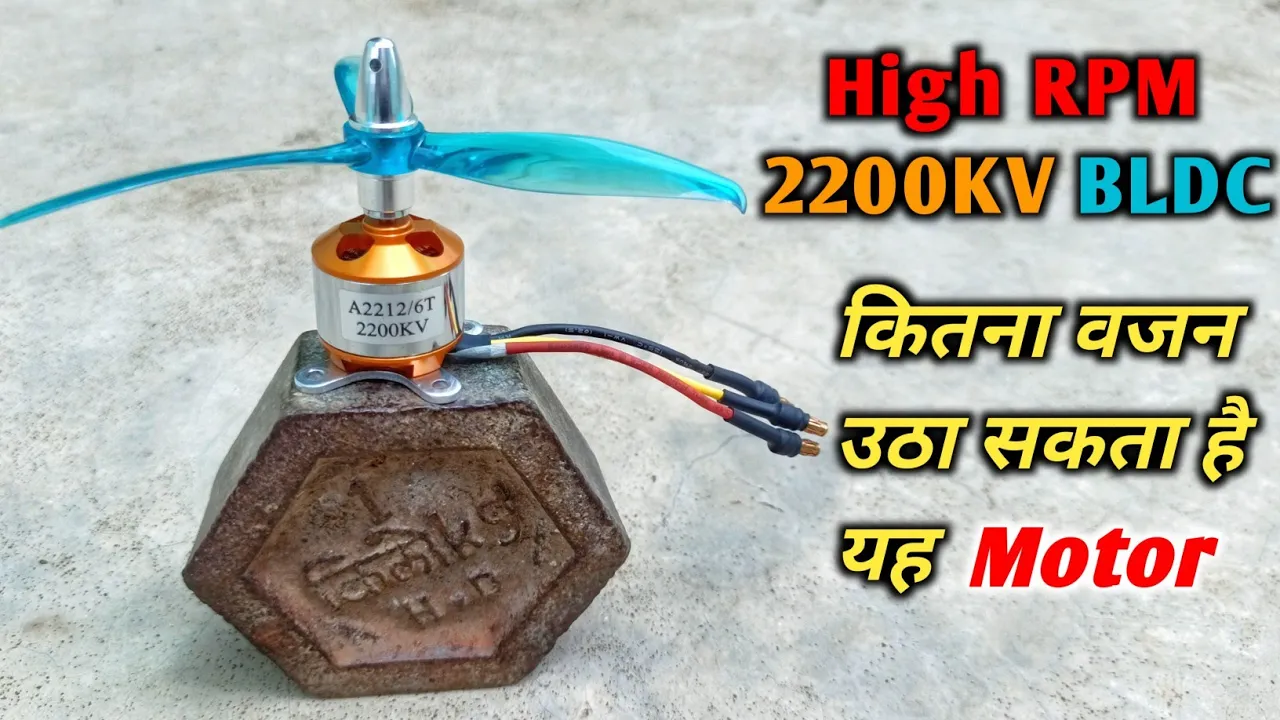
E-Flight power 60 motor. And this thing is a beast.
Excited about this. Problem is, it's a monster. So, it's going to change my weight and balance. It's going to change the distance from the prop to the cowling. I'm going to have to redesign the motor mount. So, what we're going to do is we're going to do a little bit of thunder laser cutting over there with some pieces. And I'm going to assemble this bad boy back together.
Okay, now I got this sucker off. Man, that's a big cowling.
And here's the problem.
This new motor is going to sit it's like about an inch further forward. So, we're going to have to redesign this motor mount and bring it back by about that far. So, I'll show you in Fusion 360 what we're doing.
So, here we are. We're in Fusion 360.
I've got the full model pulled up. First thing I'm going to do is I'm going to hide the cowling so we can see what we've got to work with. And now, you see this red motor mount? This was my first attempt at making one that was 3D printable. And I thought it was cool, but it wasn't strong enough. So, I'm giving up on that. This actually broke on me. I went with a laser cut mount for the motor. And this is the one that we're going to be adjusting here. So, what I'm going to do now is I'm going to bring in a model of that E-Flight motor that I had gotten somewhere else, assuming that it was actually correct.
It actually wasn't 100%, but it was good enough. And now I'm moving it to align the back of the spinner plates so that I can see how much we've got to remove.
Now, I'm getting rid of that old motor.
I'm getting rid of that ugly prop. And I'm going to get rid of the 3D printed section of the original motor mount.
Then using the back of the new motors mount, I'm going to line the motor up with a plane so I have it centered in both directions.
And now I'm going to use the trim command to trim the existing motor off back of the new motors mount. Next thing I'm going to do is I'm going to extrude the existing walls of the motor mount out 4 mm. And then I'm going to use the split tool command.
Clip it right at the first opening. The idea behind this motor mount is that it's going to just slide over the top of the existing. So I'm going to rename it here. And then I'm going to create a component out of it.
And then do a circular pattern of that one component using the axis of the motor.
rotate it and put it in four positions.
So, it's essentially it's the same component all the way around.
Now, I'm going to modify it to the slightly bigger shape so that it will slide over the existing. Now, we're going to check this for all four sides.
And now, I'm going to draw a front circular mounting plate, the motor adapter. Again, I'm going to extrude it back 4 mm and say new body. So, that's one of two that I'll be making. Going to make it just a little bit bigger than the adapters.
Now, I'm going to use the split tool.
Cut the outer shell bodies again because they're components. It cut it all the way around. Now I'm extruding and creating a new body for the secondary plate that's going to go inside the actual motor mount, but it's going to be a little bit different shape. It just starts out as this. So I have my secondary piece of mount here. I'm using a split tool to cut the existing mount and I'm deleting these little curved pieces. We won't need those anymore. And curved pieces of the existing mount will end up being sawed off. Remount this.
I'm joining bunch of bits here to the front. because I want these little square pieces to line up. It'll be easy for for me to mount this forward firewall piece later. I'm isolating it.
And it's a little bit of a mess. So, what I want to do is create a cylinder right on the front. And I'm going to allow the operation to cut and it cleans that right up. There was a little bit of trash that I'm just hitting the delete key and it's automatically healing itself with. They all cleaned up. That's exactly the shape I want. I'm isolating it now. and we will begin working on the back piece. Going to use the split body command and touch the edges of the side mounts so that it cuts straight through it. And I'm going to do the same thing on the sides so that it's going to create a plus shape. Now I'm going to join those interior pieces together. And right here I am tired of seeing the whole model. So I'm creating a section plane, but I have to turn analytics on to be able to see it. Now I'm only looking at what I want to edit. There's a little bit of the remainder here that I still want. So I'm going to do the join command and use the cut feature.
We'll do this all the way around the model. It's kind of a sloppy way to do this, but sometimes you get going down a road and you just keep going.
So now we see the plush shape that we have that I wanted. Now I'm going to use split body command again. Going to split a hole right at the mount point. Turn off the motor to extrude that body out.
Move it back through both plates. And then I'm going to use the circular pattern tool. Select body. And then the axis will be the plate. I'm going to set it to a count of four. We'll touch both faces or all four faces here. And launch extrude command tool. Run it straight through. It cuts everything including the cylinders you just made. Now I have both my plates exactly the way I want it. unisolating everything. Turning off my section analysis, me hide my cowling again. So there we go. That's going to be the new motor mount shape. Once I cut the existing mount behind it, it'll all clean up just nicely. Here's an important point is that laser cutting is very much a two-dimensional operation.
And if you zoom into these parts, we have tapers on them and that makes for nonsquare edges. And so we need to really be careful about which edge it is that we choose to create a profile from because the profile is what we're going to send to the laser cutter. So for example, this piece, if I did this outside edge, if that was a two-dimensional shape, it probably wouldn't fit in that space.
For example, if I extruded this right here, you see it extruding square. You see how it's getting larger and it wouldn't necessarily fit between the sidewalls. So, I would choose the outside face of that one. And on the front motor mount, I'm actually going to choose the inside face right there to create my profile. So, you see that it just said I'm going to create a TXF or sorry, create a sketch.
Believe it or not, it's already done.
Just because I said to create it, it found the boundaries for me and it created it. I'm going to hide that one.
And I need to isolate the back plate.
Turn the sketches off. I'm going to see how the sketches are still showing the one that I just created. So I'm going to turn sketches off. Touch on the face.
Right click. Create a sketch. And now I'm going to immediately hit done. Turn all of these back on. Now since the sides are all identical, I'm just going to create one of them. I'm going to touch a face, right click, say create sketch. And now that sketch is also done. So, if you look in my list here, I have sketches that sketch one, sketch two, sketch three. And now I can double click on them and rename them whatever it is that I want to name them. There's sides, there's front, there's back. Now, it's simply a matter of taking them and exporting them out to a DXF file. But before I do that, I'm using LightBurn and I have found it to be a real problem. I draw in millimeters on these drawings. But Thunderjet and LightBurn tend to default to imperial units. So before I do this, going to go to my model units here.
Right here under document settings, I'm going to change my units to inches. This will make life perfect. So now I'll go back to my sketches. So now I'll export to DXF. Export it out. And these are the only thing that will go in to the LightBurn software. As far as the LightBurn software, we won't spend a lot of time on this, but I will literally drag and drop these DXF files onto the build plate. I will set up power to be at 90% and I'll set my speed to about 45. And that's just recommended settings for the plywood for uh this specific laser cutter. And this is what you'll about to see.
[Music] Well, this is why you measure twice and cut once, even if you're using a laser.
My holes don't line up. Dang it.
It's like 70 mm.
All right. So, second time's a charm here. Now, I'm going to go back through and we're going to create a sketch to exactly what the caliper said to create. I'm going to do this much in the same way I did the first one. Just create these cylinders. I could have done this by a number of different ways. I just tend to lurking with models. Deleting the old geometry, old holes. And now I'm going to delete the ones on the front and then could have drilled a hole. You could have done a number of things, but I'm just going to take the cylinder and I'm going to use a pattern circular array just like I did before. And there are my four. Now I'm touching all four faces.
I'm going to use the extrude command and punch them straight through. You could have chosen to do this by drilling holes, but I just did it this way.
>> All right, so that's it.
[Music] So now I'm just checking the alignment here. And this is going to be a simple laminating with 5minute epoxy.
>> I'm just letting the epoxy set. This slid right over the old one. Cut it back about an inch. It should actually be stronger than it was to begin with.
>> So, here's the story behind this model and how it came to be and why I'm sharing it with you. This started as an experiment. I've always loved 3D printing and I've built plenty of 3D printed planes, but at the same time, I have a real soft spot for traditional models. I've built them all my life. To me, they're just more beautiful. They fly better. They are tougher. And when something breaks, you can actually fix it. So then I thought, well, what if I didn't have to choose? What if I could combine both worlds into one design? And that question is really where this project began. I wanted to create a hybrid, something mostly 3D printed, but with enough traditional construction to make it stronger, lighter, and actually easier to build. Now, the first version came together in kind of a patchwork way. I printed most of the parts in PET G with this neat interlocking system that just clicks together. Some parts I swapped out for laser cut pieces because the strength to weight tradeoff was just too good to ignore.
Few balsa stringers slipped in for the same reason. Sometimes wood just wins.
Now for the canopy, I pulled out the vacuum former because I wanted clear glass. And when it was all done, I wrapped the whole thing in Ultra Coat just to give it that finished look. No layer lines here. And here's the thing, I didn't set out to make this a downloadable model. This was really just a labor of love and experiment, just me chasing an idea to see how far I could push it. But now that it's finished, I thought, why not share it? So, yes, the files are free to download. They're on my website if you want to try printing your own version. But full honesty here, I haven't had a chance to fly yet. I can blame the motor or just I'm a little bit apprehensive about it. So, it's sitting here ready to go, but life and work have kept me grounded. And the same for documenting the build. I've started putting some notes on my blog about how it's done, and I'll add more as time allows. But for me, the fun was actually the journey. Taking an idea, experimenting old and new techniques, and ending up with something unique. And if you decide to build one yourself, I'd love to see what your version looks like. So download, give it a try, reach out to me. I'll try to make some follow-up videos where people are getting stuck. See if I can't help out.
Anyway, happy flying.
Up Next

39:01
Fusion FEA Tutorial: Beginner Stress Analysis Walkthrough
@bradtallis8968
2.8K views•2026-01-02

30:32
Ultrasonic Transducers: Resonant Frequency Measurement and Horn Design
@imajeenyus42
229.9K views•2017-02-22

54:16
Polymer Environmental Degradation: Mechanisms & Stabilization
@iit
1.8K views•2012-07-10

33:39
How a Student's Question Saved a NYC Skyscraper from Collapse
@veritasium
22.8M views•2025-04-26
Related Study Plans & Knowledge Roadmaps
Structured learning paths in Engineering
engineering
Building Acoustic Levitators: Physics & Arduino
01The Physics of Sound and Standing Waves
02Piezoelectric Transducers and H-Bridge Drivers
03Arduino Programming: Generating 40 kHz Signals
+ 2 more learning modules
14h5 modules
Explore Roadmap
engineering
Building Peltier Cloud Chambers: Particle Tracks
01Cosmic Rays & Cloud Chamber Physics
02Thermoelectric Cooling (TEC) Fundamentals
03Custom Liquid-Cooling Loop Design
+ 2 more learning modules
18h5 modules
Explore Roadmap
engineering
Yagi-Uda Antennas: Modeling, Build & VNA Test
01Introduction to RF and Antenna Fundamentals
02Yagi-Uda Antenna Design Principles
03Antenna Modeling and Simulation in 4NEC2
+ 2 more learning modules
18h5 modules
Explore Roadmap
engineering
ECG Monitor Design: Op-Amps, Filters & Noise
01Electronics & Breadboard Basics
02Op-Amps and Instrumentation Amplifiers
03Bioelectricity and ECG Fundamentals
+ 2 more learning modules
18h5 modules
Explore Roadmap