![[3D모델링 기초] 3D프린팅을 위한 모델링 배우기!! (FUSION 360)](https://i.ytimg.com/vi/puqWcAl82JU/maxresdefault.jpg)

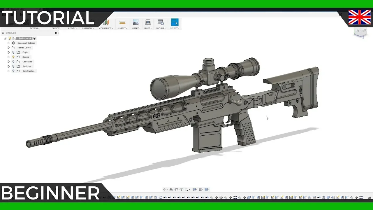















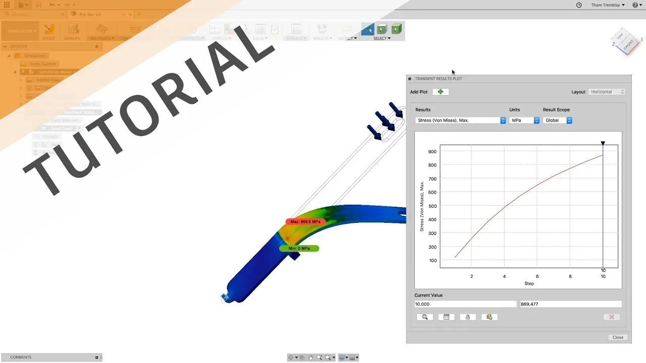
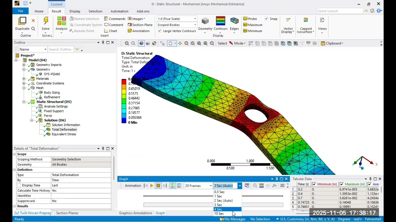



This video tutorial introduces beginners to Finite Element Analysis (FEA) in Fusion 360, demonstrating the complete workflow for running a static stress simulation: creating a new study, simplifying the model by removing unnecessary components and features, assigning appropriate materials, applying constraints to stationary areas, adding structural loads (force and moment), using the pre-check icon to validate setup completeness, running the solve locally without cloud credits, and analyzing results including safety factors, deformation, and stress distribution to determine if a design is over-engineered or under-engineered.
Fusion FEA Tutorial: Beginner Stress Analysis Walkthrough
Added:Basic proficiency in Autodesk Fusion 360 CAD modeling, including navigating the workspace and manipulating 3D geometry.
Fundamental concepts of mechanics of materials, specifically stress, strain, and the relationship defined by Hooke's Law.
An understanding of material mechanical properties, such as Yield Strength, Ultimate Tensile Strength, and Young's Modulus.
The principles of static equilibrium, including how external loads (forces, pressures) are balanced by constraints (boundary conditions).
Techniques for mesh refinement and performing mesh convergence studies to verify the accuracy and reliability of the FEA model.
Advanced simulation types in Fusion 360, such as Modal (vibration) analysis, Thermal Stress, and Buckling studies.
Nonlinear stress analysis, which accounts for material yielding (plasticity) and large deformations beyond the elastic limit.
Topology optimization and Generative Design to automatically lightweight and redesign components based on stress results.
2.8K views201likes39:01Original Release: 2026-01-02
In this video, I'm going to be talking about FEA or finite element analysis.
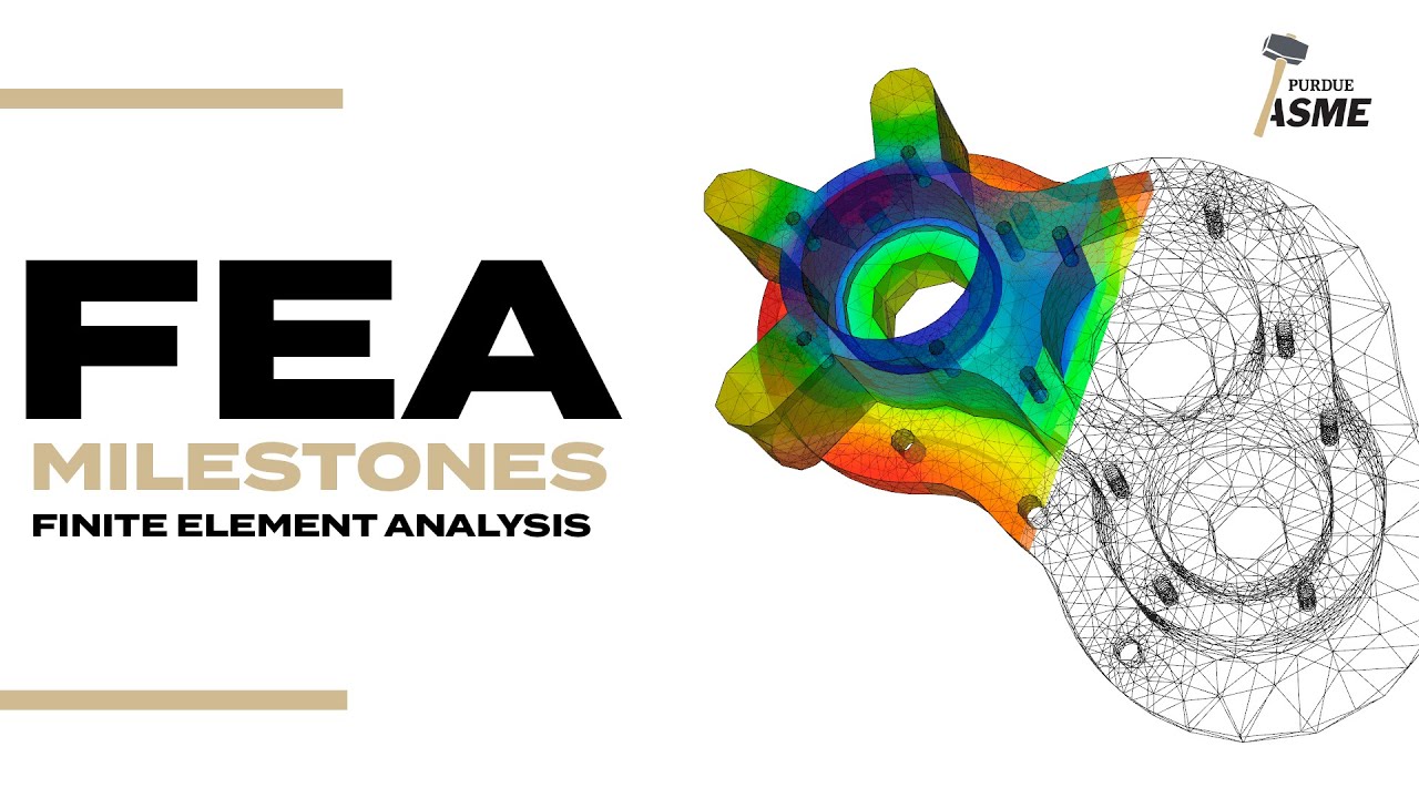
FEA breaks down your design into finite elements or small chunks which then equations are applied to and then combined all together to approximate the behavior of the whole system. So let's take a look at how this works.
So, in this example, I want to simulate how strong this plate is on this drone that I downloaded from GrabCAD.
So, I'm going to jump into the simulation workspace.
And you can see it brings up this study dialogue, and you can see all the different types of studies that you can do such as static stress, modal frequency, electronics, and thermal, etc. There's a bunch of different ones in here. We're only going to be talking about static stress as this is the only one that does not cost cloud credits to solve. The rest of these are a little bit more advanced and they require cloud credits because they actually get solved out on the cloud. Um, you can notice here it says help me choose a study type. If I click on that, it actually explains what each of the different studies do. And some of these are pretty impressive such as like dynamic event simulation, shaped optimization, injection molding simulation, etc. But we're going to do just a static stress.
The other thing I wanted to point out is this little icon right here is actually your settings. Um, now you'll notice I can click on mesh and it's going to use the average element size. And right now it's set to 10% of the model. So you can kind of see I can drag this slider around. And by default it's set to 10%.
I also have the ability to scale the mesh size per the part or to specify an absolute size. I wanted to point that out because sometimes you'll do some calculations and you want to have a finer resolution mesh and you can actually set that here in the settings.
You can also change it later on, but I just wanted to point that out at the beginning.
You also have some advanced settings here. I'm not going to go into too much detail, but you can kind of see, you know, are we creating curved mesh elements? Are we doing parabolic or linear element order, etc., etc. And then we have adaptive mesh refinement. And this is actually pretty cool. Right now it's set to none. But what this allows you to do, if I were to crank this up a little bit, you can see um for example, if I go to medium, the maximum number of mesh refinements.
Obviously, this is going to take longer to calculate. But what it does is it runs a solve and then if it needs to, it's going to run a solve again to get a higher resolution and then it's going to run it again and again basically four times. Um each time getting a better and better resolution to get a better and better result. So, by default, it's set to none. It's just going to run it once and give you a result. This is actually pretty nice. It gives you a much better solution if you're going for that really uh fine result.
Okay, so we're going to do a static stress. So, I'm going to say create study.
And now you can see that we're in the simulation workspace. We've already created our study. So, the next thing we're going to do is this simplify. I do not want to simulate the whole assembly.
All I'm really care about is this base plate. So, I'm gonna say simplify.
I'll expand open my model components.
I'm just going to click on this base plate to kind of figure out which of these components it is, which is this one right here. So, I can rightclick and say remove all except the selected.
So, I'm going to say remove all except selected. and it removes all of the other components and now it's only going to simulate this singular component.
The other thing is since we're still in simplify, you'll notice there's a bunch of holes in here. And what I'm really kind of concerned about is what's going to happen to these motor arms uh as you know we turn on the motors and you know do some high torque moves and all that kind of stuff. What's going to happen to these [clears throat] arms? So these holes really aren't necessary. And with FEA, which stands for finite element analysis, this model is going to get broken down into small triangular elements or finite elements. So the more um curved sections you have, the finer those elements need to be. And these holes really don't matter. So we could go ahead and probably remove those. So under modify, we have remove features. You can see a bunch of colored items and it's set to select all.
So it's looking for fillets and holes and chamfers and extrusions etc. And this feature size allows us to specify what size of these features do we want to select.
So for example, let me go ahead and um do fillets. And we can see that there's these small fillets, but then there's some larger fillets that aren't selected. But if I were to drag the slider to the right, we're going to see small fillet, then these medium fillets got selected. If I keep dragging to the right, then we're going to see the larger fillets get selected. And if I continue to drag, we'll finally see the really large fillets start to get selected, like so.
So, that's what this slider allows you to do. Now, what we care about are these holes. So, I'm going to go ahead and select hole. I'll drag this slider. And you can see it's going to select all of these holes right here. But you'll notice it didn't select these motor holes until I keep dragging the slider farther and farther until finally it selects those motor holes, which we don't want to get rid of. I just want these smaller holes like so.
I'll hit delete and it removes those out of the design. And what's cool about this is it's only removing it in this simplify mode. It's not physically changing the actual model. So if I say finish simplify and we jump back to the original design, you'll see that the holes are still there. But if I go back to the simulation, we can see that they are not in the simulation model.
The next command over is the materials menu. And if I click on materials, we can see that this model was designed out of aluminum.
Now, I want to see if we could make this as lightweight as possible. So, I'm going to come in here and instead of saying make it out of aluminum, same as the model, let's go ahead and analyze it if it were made out of ABS plastic.
So, we've just assigned ABS plastic to this model. Continuing from left to right, the next menu over is constraints. And what constraints do is allow you to specify something that you want to be stationary. And all of the other forces are going to react against those stationary faces. And what we're trying to figure out here is like what's going to happen to these motor arms as we you know crank up the electric motors with high torque um you know and they're you know high speed and all that kind of stuff. We want to see what's going to happen to these arms. So I'm going to say basically this tray area here is going to be our stationary area that we want to be constrained. So I'll go ahead and click on constraint.
And you'll see there's many different types such as fixed and pin and frictionless. etc. We're going to go ahead and leave it as fixed. And then you'll also notice we have different axes such as X, Y, and Z. And you can actually toggle whether you want something to like rotate freely around the Z-axis if you wanted to. Now, in this case, I'm going to just select, let me go like so. I'm just going to select this region here and say okay. And we just selected all of those faces to be fixed. And you can see they have all these little lock symbols on them. So we're telling the simulation that those faces we don't want to move.
Now there's a bunch of different kinds of constraints. Um, you can see we can do structural constraints, but we also have what's called like bolt connectors.
So, you could specify if something's bolted together. We also have like rigid body connectors, etc. I'm not going to cover all of these different commands.
The next one is loads. And there's a bunch of different ones in here. We're going to focus on structural loads, but you can see as you hover over each of these, like we have linear global loads, angular global loads, you can toggle gravity on or off. You can even edit what the gravity is. Um, but this is really useful for other types of simulation. Um, but in this case, we're going to do just a standard structural load. And in that, there's many different types such as force and pressure and moments, etc. We're going to deal mainly with force and moment loads. So what we're going to simulate is basically the pressure or the force of the propellers pushing down on these arms. And then we're also going to simulate the moment or the torque of the motor on these arms. So we're going to do two separate structural loads. So the first one we're going to do is just a regular force and it's asking for a target. And again I'm going to focus kind of where the motors are mounted.
So, I'm going to select this cylinder right here.
Now, you'll notice it kind of gives me a preview of this arrow. Well, I want to push down. And we have this direction type of normal, angle, or vectors. So, I'm going to go ahead and select vectors. And now, we can specify in which direction we want the force to happen, X, Y, or Z. And in this case, we want it to happen in the Z direction.
You'll also notice the N and that is the units here. So, if I click on change units, we're in Newtons. Well, I want to say pound force because I I did some research on the motors and I know that they can output 4.4 pound of force. So, I'll go ahead and type in here 4.4 lb.
And then I'll go ahead and you'll notice that the arrow is pointing up. So, I'll say in the negative direction. And now the arrow is pointing down.
And I can select all four of these cylinders.
And then you'll notice there's this force per entity. I'll go ahead and check that on because each motor can output 4.4 pounds of force. So, I'll go ahead and turn that on and say okay. And we just put 4.4 24 pounds of force down on these cylindrical faces.
Now, I'm actually going to undo that really quick because I want to point one thing out. I'm going to undo and I want to point out this pre-check right here.
You'll notice that there's a red exclamation point and it basically says the study cannot be solved. Let me go ahead and click on this and you'll see it says incomplete setup missing structural loads. Click here to select structural loads. So, it's telling me that it doesn't have enough information to be able to solve. Now, I'm going to go ahead and hit redo. So, now it put my loads back on there. And now, you'll notice there's a green checkbox.
So, if I click on this, everything is good. The study has all of the information required. So, this is a cool little icon to take a look at as you're going through and doing your analysis and setting up your materials, your constraints, your loads, etc. because it'll tell you, does it have everything that it needs before you can run the solve?
And we're actually going to come back to this in another example here in a moment. Okay, so we now have our loads specified, our force, and we also have our fixed constraints.
I also want to simulate the torque. So, I'm going to go ahead and do another structural load, but this time I'm going to say it's a moment.
I'll select that same cylinder.
And with drones, you have four motors, but two spin in one direction and two spin in the other. So, I'm going to select these two motors here to spin in the same direction.
And I did some calculations and I'm going to type in 83 Newton meters. And this is Newton millimeters. So, I'm going to change my units to Newton meters.
And I'm going to set this to be uh 83.
Now what I used was the formula torque equals power * 9550 divided by the speed. You know this was a formula I found on Google to figure out torque for this particular size motor. Uh and the result was 83 newton m. So I'm going to do it in that direction for those motors.
I'll say okay. I'll repeat that command.
I'll say moment and then I'll pick these two specify that to be newton meters again make that 83 uh but I'm going to say flip directions so they're going to go in the opposite direction and I'll say okay so we now have created two different moments forces on these arms once again the pre-check is green. So now we can do the solve. So I'm going to go ahead and click on solve. You'll notice it doesn't require any cloud credits. And this is the key thing uh for the static simulation. Uh it does not get solved out on the cloud. It gets solved locally.
We can see the percentage here. Um I'll go ahead and speed this up for the video. uh this will take some time to solve.
Okay, we can see that the uh results are done and unfortunately we have a very low very low um safety factor. Uh which kind of makes sense with this being a made out of ABS plastic and these being very high torque, very strong motors. Um and this is a cool result. that's telling us that this design is expected to bend permanently or break under the current analysis criteria. So making this out of ABS plastic is probably not a good idea.
Um, and that's kind of what this simulation has proven.
So what we can do now is let's finish our results. We'll come into the study materials and let's change that back to aluminum.
I could say same as model or I could even pick a specific aluminum out of here. I'll just go ahead and pick standard aluminum and let's just rerun the solve and see what the results we get this time.
Okay, so this time we got a minimum safety result of 1.77 made out of aluminum. And as we look at this, we can kind of see it's showing us a flag of where the minimum safety factor is, and it's kind of pointing to this small fillet. Um, and so basically saying that's kind of the weakest point. In fact, there's a cool option right here, show weakest areas of design. I'll go ahead and select on that, and it kind of highlights, kind of grays everything out and kind of highlights the weakest areas. Um, and so we can kind of see where those weakest areas of the design are. So it kind of looks like in this fillet right here is that 1.77.
Now, typically you want your minimum safety factor to be somewhere between like three and six. So it would be nice to get this a little bit higher.
So, what we could probably do is maybe increase the size of that fillet. So, let's go ahead and finish the results.
Switch to the design workspace.
Let's see. That's this guy here. I'm going to go ahead and isolate.
And let's just make that fillet be a little bit larger. So, I'll select both of those fillets, do a press pull, and let's just maybe make those 3 mm in radius. So, we're just kind of enlarging that radius.
And we'll switch back to this simulation workspace.
Now, I want to keep everything that I've done in this study so far. So, I'm going to rightclick on study one and say clone study.
What it just did is we now have study one and now we have study two. And that way we can always come back and look at the results of study one. And we're working on study two now.
So let's go ahead and solve with this new updated fillet here. So I'll hit solve.
We'll let that run and see what the safety factor is on that.
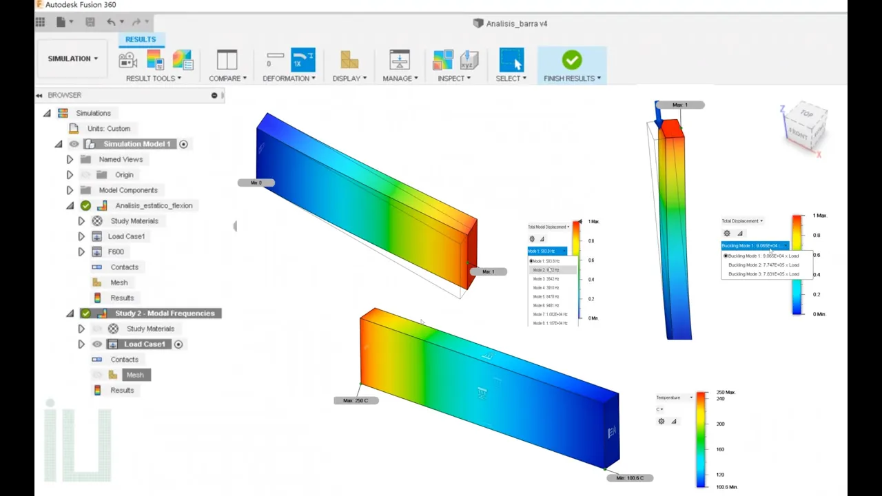
So now we can see with this one, we got the minimum safety factor almost up to two in this case by changing that radius there. And now it's telling us our minimum safety factor is in this small radius here. So again, we could probably go and fix some of these smaller radiuses, maybe enlarge them a little bit, but a safety factor of two is not too bad. It's, you know, pretty close to three. Um, so I'm going to call that good in this case. Um, but what I wanted to show next is this was the safety factor. Let's change this to stress. And now we can visually see where is the stress happening on these arms with these motors. And you can kind of see these shadow lines right here. And then you can kind of see these colored lines.
And what this is is this is basically exaggerated deformation. And that's in this menu right here. So you can see we have undeformed at all. So, this is as design.
And then we have actual. And it's hard to see the change there, but I'm going to zoom up pretty close to here. So, this is act um undeformed. Then I'm going to hit actual. And you can see it move ever so slightly, and you can see the slight difference right there. So, it's physically showing us the difference when this thing is under load.
What's going to happen to these arms? So that's how much it's going to move while it's under load. While it's constrained here and it's putting the torque and the pressure on these aluminum arms, that's how far they're going to move. So we can see that they're moving down a little bit, which makes sense cuz the motors are pushing them down and then the torque is kind of twisting them off to the side, which also makes sense for these uh motor arms.
Then we have adjusted and that's basically kind of an exaggeration to kind of give you a better visual representation of what's really happening to these arms. And you have different options here. You could say adjusted two times, you know, you could say five times, which is obviously an overexaggeration, but you can kind of see things are getting pushed down and they're getting torqued off to the side.
So, I usually do adjusted because it it does kind of give you a visual representation of what's happening.
Then, what's kind of cool with this is under the results tools, we have this animate.
And what this allows you to do is to create an animation of this. If I just hit play, you're going to see it kind of step through for 10 frames.
Now, what I like to do is I like to turn on two-way and hit play. And then it's kind of like a pingpong where it kind of goes back and forth and you can visualize frame by frame what's happening. Now, the more steps you put in, the more resolution you're going to get. So, if I type in 20, you're going to see it's going to do more frames in between. It's going to go a little bit slower, but you're going to see there's basically more frames.
Then, we also have the speed. So, I'll go ahead and change that to like fastest. And now you can kind of visually see what that looks like, how it's animating a little bit faster.
We also have legend options.
And one of the things I like to do in here is this color transition. You'll notice it says smooth. And you can see how it's kind of going from this red to this blue.
You also can do banded and it kind of changes it to, you know, like almost like banded colors instead of the the uh smooth option.
And it kind of highlights things a little bit a little bit more evident, I guess. Um, some people like banded, some people like the smooth. It's really up to you. Then we also have this compare option. So, I'm going to go ahead and click on compare. And you can see that it splits the window into two separate windows. And this allows you to compare two different simulations.
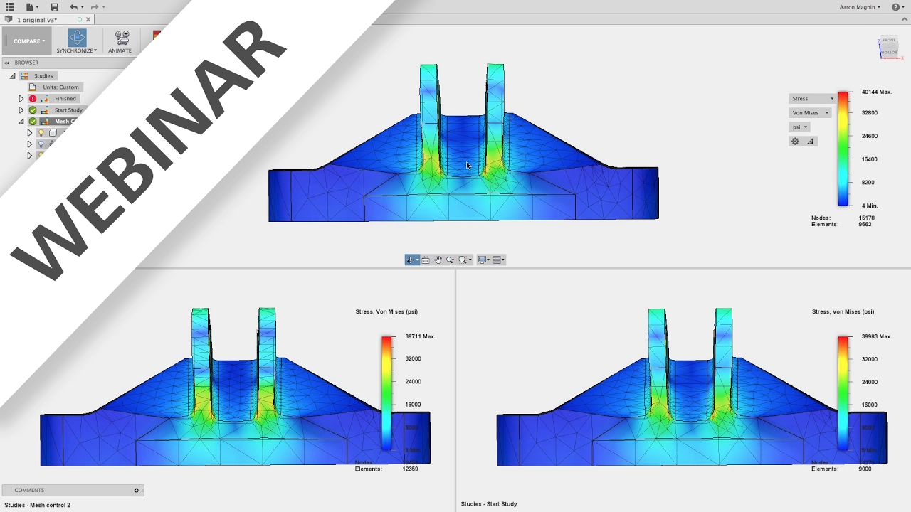
So for example, if I click on this right here, I can look at study one and we can see on study one our minimum safety factor was 1.7 and in study two our minimum safety factor was almost two. And we can kind of compare and see what the differences are. We can see here is the small fillet. Here is the larger fillet.
And you can come in here and say let's take a look at stress. Same thing over here. I'll come in and take a look at the stress. And we can kind of, you know, zoom up on key areas and see is there any difference in these areas.
Another thing I like to do is if I grab these little triangles on the legend, it'll actually filter out.
So, for example, let me start from the bottom. Let's go like this.
And it's just going to highlight kind of the high stress areas.
And so, I can drag this up to let's just do maybe around 70. And then we'll do the same thing here.
And so we can kind of visualize, you know, in the two different results, you know, this one here with the larger fillet, is it putting more stress here than it did with the smaller fillet here? Um, you can kind of analyze that.
Kind of a cool little trick.
We also have displacement and this is showing like how far things are moving. So obviously since these are constrained right here, they're not moving at all. And then we can see again in millimeters, these are moving about 6 millm in actuality.
So if we come over here, let's do displacement. Um so point this is 62 this is 6. So by changing um that fillet we're getting a little bit less movement here. So it's kind of cool being able to compare the two right next to each other. Now um this would make more sense if we were comparing two different materials. You know maybe aluminum versus steel or something like that. You would see obviously a larger difference.
Um but even just making minor changes like the change of this fillet is giving us different results in different um you know like stress and displacement etc. So I'll go ahead and finish that compare.
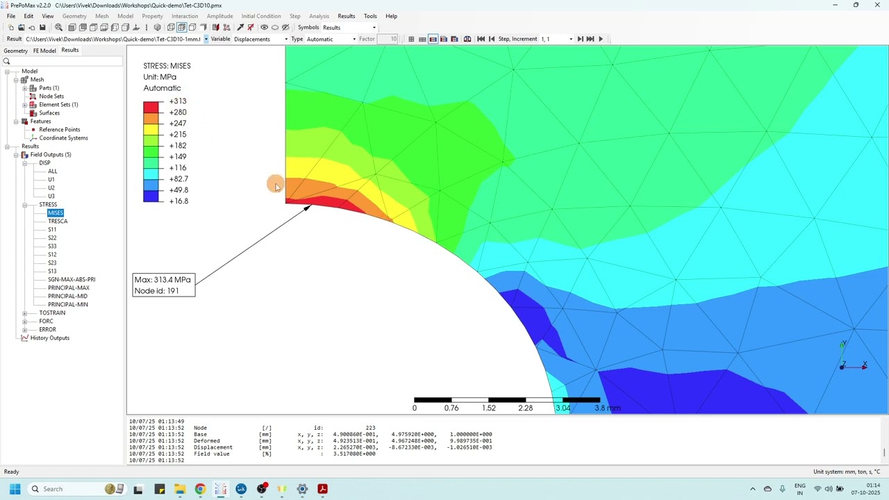
The next thing I want to show is under display we have this mesh view and this is showing all of the finite elements and this this kind of gives you a visual picture of what's actually happening. So you can see how larger flatter areas are broken down into larger triangular chunks like you can kind of see here in this region. But then fillets and small curved areas are broken down into these smaller finite elements. And this is why I removed those holes earlier because you could imagine every single one of those little holes that were in here would have to have a bunch of these small triangles to calculate.
You can kind of see those all throughout here. Each of these fillets have very small finite elements that take longer to calculate. and larger regions are these larger triangles.
Another thing I like to do in the results is let's go ahead and turn off the mesh view and let's turn this back to smooth and let's do maybe like stress. Um, what I like to inspect, there's a lot of options in here. So, you can see you could hide the min and max labels, which are these right here. here. If I turn those off, they go away. Um, you have create surface probes, and this just allows you to kind of like drag over the design, and it'll give you results anywhere on the design.
You also have point probes where you can pick a particular point and it's going to tell you what the megapascals at that particular point and that location are.
Um, and then you have like center of mass, but I also like this slice plane.
What this allows you to do is pick a plane. You can actually see inside the design. So you can actually see what's having happening inside right there for example.
Let's kind of slice right here. And you can see what's where the strain and stress is happening not just on the surface but inside the design um as we kind of slice through here. So we can see obviously the stress and strain is on this lower corner here versus up here. So that's kind of a cool option in the inspect menu.
Okay. Now, now let's say we want to simulate what would happen if we actually like crashed our drone into like a wall or something like that. So, I want instead of just the plate, I want the whole drone. So, I'm going to go ahead and close this and bring up let's just bring up the original drone.
And I'll save this as um a new version here. I'll call this drone impact.
And we're going to kind of do the same thing, but like I said, I want to simulate it with, you know, more components. I want most of the frame.
I'm not I'm not going to calculate like the circuit boards or the propellers or anything like that. So, we'll jump back into simulation.
We'll do a static stress.
Now, typically we would probably want to do a a dynamic event simulation. This is more for like, you know, how your design responds to rapidly changing loads and constraints. you know, like for example, in this case, it's showing like something hitting a helmet like a baseball or something like that. What we're gonna kind of simulate that is what would happen? How would these parts deform if something um you know pushed against it? That's what we're kind of simulating in this case. So once again, I'm going to do a simplify. I'll expand this open. And instead of selecting one and removing everything except for that, what I'm going to do here is select a couple components, rightclick, and say remove. So instead of remove all except selected, I'm just going to say remove.
So for example, I'll select these motors here and remove that out of there. We don't need um these guys. I'll remove them out of there. I think these are the the uh blades. So, let me uh select those.
I want that. These are the stands. I want those guys. We don't need that one.
Okay. So, we're left with this. And this is what I want to simulate.
I'll check my materials. I can see that everything is made out of aluminum.
Okay, I'll go ahead and simplify um this part here.
Remove features on this body. We'll select those holes. I'll go ahead and delete those out of there. Um I could do the same thing on um you know some of these other parts, but for now I'll just leave them for now. But like I could probably remove these chamers and fillets that are on here, but to save time, I'm just going to leave those for now. Okay, I'll add my constraints.
Now, you'll notice this pre-check right here has the red icon on it. If I click on it, it's giving me a lot of information missing structural loads.
So, I need to create some kind of structural loads. So, I could click here to select the structural loads, or I could go up there. So, I'm going to go ahead and select right here. It takes me right into the structural loads menu, which is pretty cool. Now, what I want to simulate is like we basically hit a brick wall or something like that. Maybe a corner. So, instead of both of these faces, I'm going to select just this face here because we're kind of flying forward at high speed, you know, like so. And so we're going to maybe hit this surface right here. Um, right now it's in Newtons. Let's change this to maybe pound force. And I don't know the exact number here. I'm just going to simulate, let's just say 200 lb of force. Um, and again, this number could be 500. It could be 200. Let's just say 200 in this case. I'll say okay. And so we're basically applying 200 lb of force against that face right there. Now, you'll notice it still says pre-check is red. So, I'm going to click on that.
Now, the list is a a little bit smaller, but it says model contains six fully unconstrained groups. Click here to select DOF view. Well, DOF stands for degrees of freedom. So, I'm going to click on that. And we can see that one part is green and the rest of them are red. If I come over here, green is fully fixed. And that kind of makes sense because we fixed this part in place.
But then red is free. So what basically that means is fusion doesn't know how these red parts are connected to this green part. So I'll go ahead and click on this again. So we did the doof view.
Click here to select automatic contacts.
So contact detection tolerance 0.1 mm.
Let's go ahead. I'm going to turn on my um DOF view.
Let's do that pre-check again.
Hit generate. So, what it's going to do is it's going to automatically detect any contacts and we can see that these posts were touching this bottom part and this plate was touching that post. So it basically figured out all these parts were touching within that tolerance. And so now they are fully fixed. We can see that they're all green. And we can also see that our pre-check is now happy.
So that pre-check is a really cool command because it kind of walks you through step by step what needs to happen to make the solve work. So let's go ahead and run the solve and see what our results are.
Okay, so our results are done.
Let's go ahead and close this. It looks kind of funky right now. All blue like so. This is our safety factor. Let's go ahead and change this to stress. And again, this is an exaggerated deformation, but it kind of makes sense.
So, if we were to hit this one face, we can visually see what's going to happen to our design as it's going to kind of torque these metal posts or whatever. Now, there's some things we can do to make this a little bit easier to see. So, this is the stress. I'm going to change it to displacement. And what this does is displacement shows how far things are moving. So we can see that this back point is actually moving the farthest as this impact is happening here. We can see that this is moving from its original location all the way over to here. And so as I'm looking at this as a designer, I might say, you know what, I wonder if I should have some support posts in the back here to help kind of support the back of this frame instead of it being only supported kind of in the front and the middle. So, this is kind of a cool, you know, visual confirmation that maybe we need some kind of support in the back. Um, I'll go ahead and change this back to stress.
And another thing that you can do here is if we go into the results tools and go to this legend min max, you can come in here and specify, for example, I want the minimum to be zero and I want the max to be a much smaller number. And what that's basically going to do is change how much the color changes through the part. So if I make this a much smaller number, let's just try like 100. You can kind of see how that lightened a little bit, but not by much. Let's try 50. And there we go. We can kind of see how things are starting to kind of warm up a little bit. Let's go even smaller. Let's try like 30 in this case. And now we can really visually see what area of this design is really getting affected the most during the you know what's the highest stress areas as it's being impacted on this front face right there just by changing the min and max of this. And like I showed earlier, you can drag this up and just kind of go like so. And so you can really kind of see, you know, here's like 24 to 30. These are kind of the high stress areas.
Also, if I came in here and set the deformation to actual, we're going to see that it really doesn't deform hardly at all because all of this is aluminum.
It's just, you know, pretty gosh darn strong. So even 200 lb of force really aren't going to deform this in real life. So the adjusted kind of gives you a very visual what would happen uh you know if you really impacted and like I showed before if you did an animation let's do 20 two-way and fastest you can kind of visually see Oops that was two let's do 20 you can visually see what that would look like as it impacts the the wall right there what's happening to your design.
And that might make you, like I said, might make you change your design. Like I might add some support posts on the back of this drone just to make it almost like a solid box to help strengthen this.
So hopefully that allows you to see how you could use FEA to quickly see, did you overengineer or underengineer your design? I hope you learned something new and enjoyed that video. If you did, make sure you've hit like and subscribe.
[music] That way, you'll be notified of upcoming videos.
If you'd like to learn more about Fusion, make sure you visit my web page at cadedlc.com.
And as always, have fun learning Fusion.
Up Next

6:21
Fusion 360 Topology Optimization: Lightweight Design Simulation
@AutodeskEcoWorkshop
81.2K views•2017-04-11

30:32
Ultrasonic Transducers: Resonant Frequency Measurement and Horn Design
@imajeenyus42
229.9K views•2017-02-22

54:16
Polymer Environmental Degradation: Mechanisms & Stabilization
@iit
1.8K views•2012-07-10

33:39
How a Student's Question Saved a NYC Skyscraper from Collapse
@veritasium
22.8M views•2025-04-26
Related Study Plans & Knowledge Roadmaps
Structured learning paths in Engineering
engineering
Building Acoustic Levitators: Physics & Arduino
01The Physics of Sound and Standing Waves
02Piezoelectric Transducers and H-Bridge Drivers
03Arduino Programming: Generating 40 kHz Signals
+ 2 more learning modules
14h5 modules
Explore Roadmap
engineering
Building Peltier Cloud Chambers: Particle Tracks
01Cosmic Rays & Cloud Chamber Physics
02Thermoelectric Cooling (TEC) Fundamentals
03Custom Liquid-Cooling Loop Design
+ 2 more learning modules
18h5 modules
Explore Roadmap
engineering
Yagi-Uda Antennas: Modeling, Build & VNA Test
01Introduction to RF and Antenna Fundamentals
02Yagi-Uda Antenna Design Principles
03Antenna Modeling and Simulation in 4NEC2
+ 2 more learning modules
18h5 modules
Explore Roadmap
engineering
ECG Monitor Design: Op-Amps, Filters & Noise
01Electronics & Breadboard Basics
02Op-Amps and Instrumentation Amplifiers
03Bioelectricity and ECG Fundamentals
+ 2 more learning modules
18h5 modules
Explore Roadmap