

















![[005] 4.4GHz RF Synthesizer Board - ADF4351 - Theory, Setup, Reverse Engineering, Experiments](https://i.ytimg.com/vi/xJ0Mfuj0KUQ/sddefault.jpg)
The Raspberry Pi offers multiple methods for controlling its 17 GPIO pins, each with different performance characteristics: raw C code accessing processor registers achieves the fastest speed at 10.7 MHz but requires direct memory access; the BCM2835 library provides easier access at 4.7 MHz; WiringPi offers Arduino-like simplicity at 6.8 MHz; Python's RPi.GPIO library is easiest to use but slowest at 49 kHz; and Bash commands provide simple terminal control. The choice of method depends on the application's speed requirements and programming complexity needs.
Raspberry Pi GPIO Control: 6 Ways & Benchmarking Libraries
Added:Familiarity with the Linux command-line interface and basic system navigation on Raspberry Pi OS.
Fundamental understanding of General Purpose Input/Output (GPIO) pins, including digital logic states (HIGH/LOW) and electrical safety constraints.
Basic programming proficiency in both Python (syntax and library usage) and C (compilation, syntax, and memory management).
Conceptual understanding of software benchmarking, processor overhead, and how programming language abstraction layers affect execution speed.
Implementation of Hardware Interrupts and event-driven programming to replace resource-intensive polling methods in GPIO control.
Exploring Linux Kernel-level programming to write custom device drivers for high-performance, low-latency hardware interaction.
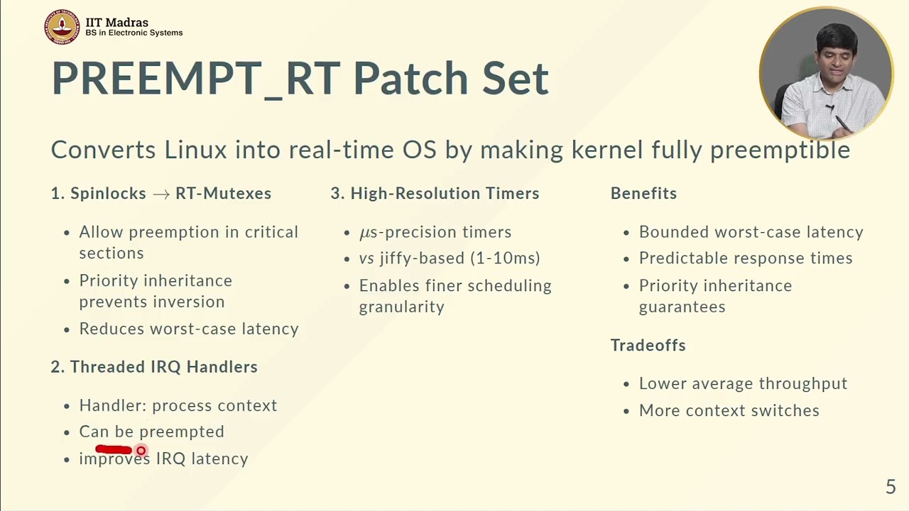
Applying real-time operating system concepts (such as PREEMPT_RT patches) to achieve deterministic GPIO timing and minimize jitter.
Designing high-frequency custom communication protocols (e.g., software-based bit-banging for SPI or I2C) leveraging the highest-performing libraries identified.
118.1K views517likes39:19Original Release: 2012-09-06
Hello YouTube. Today we are going to have a look at this new Raspberry Pi. We had this board for a while, but uh we've been playing with it and waiting till the right time for us to demonstrate the board and show you some of the goodies with it. In this uh short video, we're going to present the board itself. This is from funnel and we will be uh installing the Raspian which is the float uh the hardware floating uh operating system uh running a Debian system Debian like system together with the um X GUI interface uh that comes with it. And in the end we will have a play with the GPIOs. This board has 17 GPIOs and we will play with these GPIOs using the raw C uh SC library and other C library and also Python and in the end we'll also show a quick guey demonstration on how to control these GPIOs using a guey interface on the on the X window system.
So, uh, first off, let's have a view what's inside the box. Inside the box, we have the Raspberry Pi itself. This small credit card sized board contains a processor, 700 MHz processor with 256 MGB of RAM stacked on top. Then we have an HDMI port, an Ethernet port because this is the model B version, two USB ports, an audio jack output, and also Svideo for exchange communication. Uh we also have the GPIO port, a camera and an LCD interface, these two connectors. And finally, we of course have the power supply connector, which is this USB microB connector.
For this demonstration where we will um boot up the board for the first start and use the GPIOs, you'll need an uh SD card because on the bottom of the board there's a slot for SD cards where the uh system and the boot loader uh will uh be installed. And this is an uh 8 GB of micro SD.
if I can get it out there.
Uh, but anything above two or 4 GB will uh be enough. So, uh, you'll need an SD card. And to install the system, you'll also need a card USB card reader.
So, let's head over to uh the computer.
First plug this into the computer and then let's uh head over to to that to download and install the Raspian image.
Here at the computer I've entered the raspberry pi.org or homepage where I will go to downloads and on the download page I will find the Raspian wheezy um zip file which contains the image for this distribution.
So by clicking on this zip file I'll be directed over to this distribution homepage where I can select a mirror and download the file.
So when this has been downloaded, it is a 445 megabyte uh package. I go into my folder where I have this uh zip file, the 816, which is the latest one. I double click it and uh extract the image.
When this image has been extracted, I've got it here.
You should also download, go back to the Raspberry Pi download page, you should download, if you're on Windows, you should download the Windows tool Win32 disc imager, which is used to format and partition uh the SD card properly for uh the Linux distribution for the image contained in the zip file. And for Unix users, you can use the tool DD. For this guide, I'll be using the Win 32 disc imager, which can be downloaded here.
When that has been downloaded, you should extract it. I got it here. And you should open the Win32 disc imager.
With this one opened, you should click on the little um folder icon and select your newly extracted image file.
This 2012816 WC Raspian. Double click on that and make sure that you select the right drive, the right device for the SD card.
In my case, we have this um removable disc out here, G, which is the SD card.
And when you have uh selected that press the right and it will inform you that it will remove everything on the disk. Yes, please. And then it starts to prepare the device. You can see that it writes to to the SD card with a speed of about 4 mgabytes pers. And this will take a while. So, uh go grab a cup of coffee in the meanwhile.
And now we see that the right has been uh completed. So we will press okay to this box. And uh then we are actually finished with the computer part. So we will unplug uh close this program and unplug the USB SD card reader.
The next part we're now going to is to install or extract the image so it will run on the Raspberry Pi. This is done by plugging in the SD card to the micro no sorry the SD card slot on the back of the Raspberry Pi board. And then we will need a keyboard and later on also a mouse for interacting with the Raspberry Pi board. This is a USB keyboard and a USB mouse.
And uh further on, we'll also need an HDMI cable for the video output. And finally, also an Ethernet cable for communication uh communicating with the Raspberry Pi. And this will also make everything else as we don't need the keyboard as we can do the interaction through our computer.
So, let's hook all these devices up. And uh also, sorry, I forgot to mention that we of course also need the USB power supply cable. This is a um microb connector uh connected to a 5V power supply uh capable of uh supplying at least 700 milliamps.
So, let's hook all these things up and uh let's see what happens with the board. And now for the final part, the USB power connector.
And it's been connected. And on the screen, you can see that the Raspberry Pi powers up. We have the Raspberry Pi logo. And this is the boot screen.
And uh this is the first initial boot.
So we will soon be uh we'll soon see an initial screen where we can actually select no there it was um select what to do with this Raspberry Pi. We can configure it for the first time. This config can also be started uh second times but it will only show up automatically for this first boot. So we go down to this um expand root file system as we would like to be able to use the whole 8 GB of this card. So we press enter on that and it resizes the root position. So we can now use the full file system on the next reboot.
And uh that's actually it. We can also change the password or keyboard, but I'll leave it as it is. And uh uh select finish.
Whoops. Enter. And then it asks if we're going to reboot. Yes, please. So now the board is going to reboot.
And uh it takes a while but compared to normal computer this is nothing. It takes like 30 seconds to boot and uh another 30 seconds to get into uh the X Windows system if necessary.
But the great thing about the Raspberry Pi can see also the LEDs indicating power and uh the Ethernet.
Um but the great thing about the Raspberry Pi is that it isn't standard X enabled. you can do so in this configuration menu, but the great thing is that it just boots into the terminal and then you can start the X window if necessary afterwards.
Um, and here we see the resizing part because the resizing on an 8 GB uh takes a while because it has to partition all the other uh and then expand the the partition the root partition itself. So the other was only a setting uh which sets the resize initiation.
Now it has finished the resizing and it continues the uh boot process. And now the boot process has finished. We got the login screen. And on this Raspian uh login uh this Raspian distribution the log in the username is pi and the password is raspberry.
And now we're logged in. We get the terminal pi at raspberry pi. And it also tells us that if we would like to launch the graphical session, we should type in start x. But for now before launching this and showing this to you, I would like to update and make sure everything uh for the packages has been updated. So I write sudo for the root access and then I use apt get and then I write update and uh this might take a while because it updates all the packages.
um not the packages itself but the uh library of packages so to say.
It has now finished the update of the package list. So we can do a sudo sorry app get upgrade like that.
And then it uh checks what needs to be upgraded according to the new um library list and uh it says that it need to get 132 megabytes of archives and uh 1.8 megabytes will be freed on the SD card.
So yes, we would like to do this upgrade and this might take a while. 3% of uh packages has been downloaded. So, uh, go grab another cup of coffee.
Finally, after about 10 15 minutes of downloading and updating, it has, uh, installed the updates, and we are now ready to, uh, reboot the device for, uh, to continue with our progress. So now let's write sudo for the root access again and then shutdown slash r for reboot and it should be done now.
So when the system has booted which it has now we log in again with Pi and Raspberry as a password and uh then I will simply just get the IP address that the board has fetched from the router.
the DHCP IP address. So I write if config and we get the Ethernet zero and the IP address is this one.
So uh we can now go back to our computer um and we can actually connect to the terminal of the Raspberry Pi using SSH.
So we will be doing that instead of having to use the USB keyboard and the HDMI output.
So I'll log out of this uh session. I can't by doing that. And then it is back to the login prompt. So let's get back to our computer and open an SSH terminal connection.
And now for the fun part as we are now going to play with the GPIO outputs. But first we have to connect to the um Raspberry Pi using the an uh SSH connection. And on Windows I recommend you to do this with a program free program called putty. And uh I've opened the putty program here and selected the connection type SSH which is uh represents the port 22. And then we're going to type in the IP address we just saw in the if config output.
When we open the connection, we get the terminal login screen uh from the Raspberry Pi and we log in as the user.
And now we have access to the terminal of the Raspberry Pi. So, uh we going as we're going to play with these GPIOs, I will in this tutorial describe different ways to control that compare the speed of each. There are different ways. There are the raw way which is uh by directly using a C script uh directly accessing the registers of the processor itself accessing the GPIO registers and writing to the right peripheral to turn on and off a GPIO. That would be the fastest method but not the easiest. Another way would be to use a library such as viring pi which is a very arenous similar library which makes a uh good and fast IO toggling uh which has a good and fast IO toggling functionality together with spy and serial communication too.
Another option would be the BCM 2835 library which is the processor itself a library for the processor uh which includes uh both spy and GPIO control though this library is actually not that fast and finally we're also going to have a look at uh a Python library which makes it possible to control the GPIOs using Python and also how to control the GPIOs using raw uh no sorry standard bash commands but uh let's start with downloading the um code collection we made for this GPIO toggling tutorial first I'll make a directory called GPIO here in the home of the PI user I'll access this directory and then I will go fetch the file we have uploaded with this code collection This file can be found at our homepage in the uploads folder called Raspberry Pi GPIO.tar.
When this file has been saved, we can now extract it and we now see the different files. We have the code the C code file for the raw test accessing the registers. We have for the wiring pi library and for the BCM library and we have a Python script. And then we also have a guey Python which I'll end this tutorial with showing and demonstrating to you. But to use these codes to be able to compile them well the codes with uh which uses libraries we have to install these libraries. But uh let's first go back to our Raspberry Pi and hook up a uh pin uh to a our oscilloscope to monitor the output.
Here at the Pi, we will now hook up this oscilloscope probe from our Rial DS1052 oscilloscope to one of the output pins. In this tutorial, we'll be using the BCM output pin 18. And uh for the libraries, there are different pin numberings. The standard ones are the processor specific BCM pins, which in this case is BCM GPIO 18. But for the wiring pie, this corresponds to GPIO1, which is why I selected it.
Uh first, we'll have to connect the ground pin. And the numbering of this GPIO connector starts here which is pin one and then pin two over here 3 4 5 6 7 8 and so on. The ground pin can be found on pin six. So we count one 2 3 4 5 6. There we go.
And then we connect the output pin which can be found on out on the connector pin 12. So we count again 6 7 8 9 10 11 12 and plug it in there. And then we are ready to move on and uh compile the first raw test code um to see if we can toggle the output. Now as we have hooked up the wire to the Raspberry Pi and our oscilloscope, let's compile the first raw code which doesn't require any library. And to do so we are going to write uh GCC as the new GCC compiler is comes pre-installed with the Raspian image. And then we are going to use the uh IO toggle C raw. C file and uh we would like uh the output to be IO toggle C raw.
And when that has been compiled we uh can run this application uh by executing it executing it but we have to remember to run this as root as it is going to access the memory. So we are going to write sudo dot / io toggle c raw and then on the oscilloscope we'll notice that the I uh the output pin starts toggling and uh the output toggling is toggling at a frequency of 10.7 MHz we can see which is actually a uh pretty decent uh and fast speed compared to the processor running at 700 MHz. It might not not sound as much but as the processor is also running a Linux and this is a C application simple C application is a fair speed but you'll notice that also that there is that the the frequency is bubbling a bit and also that sometimes there is a line um as there is a timeout and these timeouts in the toggling is uh due to the interrupt processing of the Linux uh system. So we cannot avoid these. So please have this in mind if you're making some very time critical application that needs uh a specific toggling frequency. It would not be possible to do this real time with a Linux system like that. Uh in this in that case an embedded processor would be a better choice.
So for the raw library which acts as the registers directly um we get a toppling frequency of 10.7 MHz which is decent but now let's close this application stop it and uh install the BCM 2835 library which uh includes spy and the GPIO uh control uh so instead of uh rather than writing directly to the registers we can use this library which is a bit difficult but we can use it. So to install this library as uh we have to install a library to use it of course we are going to download it from the following homepage which is a bit long and the version is 1.8. And when we have fetched that we can extract it into a new directory and by entering this directory we can then compile it and install it. So first we make a configure make as we're going to make the make file for our system.
And when that has been done, we can then uh make compile the project. Uh and we do this in root and we also do a check to make sure that it can be compiled successfully.
And when it has been compiled, we install it into our Raspberry Pi by making and make install. And that's it.
Now we have installed the BCM 2835 library. So we go back to our folder with the C file. Uh and then we compile this by uh making the same GCC command as before.
CIP and then we have the BCM28.
And the output should be IO toggle C lip BCM28. But this time we also have to include remember to include our local um include folder and also our local library folder and of course also the library we are going to use in this case and then we can compile that and the project has been compiled. So we are now able to execute it in the same way as we did before. This time just with the new file.
Whoops. 2835. And then watch the oscilloscope.
Now we got a yeah a slightly lower frequency. It has actually got halfed.
um the frequency is only 4.7 MHz compared to the other 10. So that's a dramatic change and we still have the the wobbling and the the the interrupts but yet again it is easier to use this library compared to the raw code as writing to the regist is is a bit difficult but 4 MHz is still a bit so it is definitely usable. Um, but now let's have a look at the the more commonly used on the Raspberry Pi, the wiring library. And the wiring library is a uh great Arjuino comparable uh similar library um which works a bit in the same way as we can use digital right uh and pin mode for setup and uh is it is actually also uh pretty fast. But to use and download this library we have to um install the git core as the library is um uploaded to github. So first we are going to make an appget install of the git core and this of course has to be done by root.
And uh when that has been installed, we are now going to clone the wiring pi uh library, github library into our local folder. So we do this by writing get clone and then the address which is a bit long. It's jet slash jet.droen.net/wiringpie.
And when we have cloned this into the folder, we can enter the folder where we'll see three folders examples, GPIO and wiring pi. In this case, we'll be using the wiring pi folder as it contains the library itself. So we are going to do a make to compile the library.
And when we have compiled the library, we'll do a sudo make install to install the library into our Raspberry Pi.
And now when that has finished, we can go back to our folder with the code files and we will be able to compile our um wiring pi C file uh with the same command as before with the BCM. But this time we have to uh change the library name to the wiring pi. GCC IO toggle CIP wiring pi C and the output should be the same.
And we still have to uh remember to include the local include folder and the local library folder and of course together with the wiring pi library. Now as the script has been compiled, we can execute it by doing an sudo io toggle cip wiring pi and then notice the oscilloscope where we have a slightly higher frequency compared to the BCM output.
Here we have 6.8 MHz compared to the 10 MHz with the RAW library. But compared to the BCM of only 4 MHz herz 4.7 MHz, I think this is a decent library. The wiring pi library is also very easy to get started with and use uh as it simply in it uses simple commands as al as the Arduino does too. the pin mode for setting an output pin and digital right for uh controlling the IO's and uh the wobbling is also uh to be found here and the interrupts are also to be found as that is uh due to the Linux interrupt processing.
So the changes and the differences in these libraries are the the speed especially and also the ease of use.
But let's uh stop this program and go back to the computer to try out the Python library as many of you guys uh love Python. Uh there is of course also make made a Python library for the Raspberry Pi.
And yet again we have to install this library. Uh so we are going to fetch it first and this address is even longer sources R PI dot GPIO RPI RPI.gpio/r.gpio3 GPIO 031 a.tar dg g set not found. Uh uh that's one there.
Now we have saved the file. So we can write tar set xf to extract it.
And we can enter the folder where we will find the library itself.
And uh then we should uh install this.
But to install these we have to uh to install libraries we have to install another package. As Rasbian comes uh with Python installed uh you can execute Python scripts but you can't install Python uh libraries as it doesn't comes pre-installed with the Python dev package. So we have to install this using appget python dev as developer and uh this will take a while.
You can see that it need to get 28 megabytes. Uh so go grab another cup of coffee.
Now this has been installed too. So we can continue with install in the installation of this R py Python GPIO library. And to do so we write pseudo python setup pi install.
And uh this will install the RPI GPIO library.
And when that has been finished, we can go back to our main folder with the GPIO uh files. And we can execute our Python script. IO toggle Python script by writing pseudo Python. It is very important to remember the root axis. IO toggle_python.py.
And here on the oscilloscope, we notice a very low frequency compared to the other twos.
Here we only got uh 49 kHz compared to the megahertz scale. So if you're using Python, you wouldn't be you would you won't get any high frequency toggling. Um so I definitely recommend uh to stick to C libraries, the wiring PI for example, if you're going to do fast toggling. But if you're only going to do simple LED turning on and off and you're very used to Python, I would definitely recommend to to use the R py Python instead of changing to uh the C library.
So uh that's it for the C and the Python, but there's also another option.
Now I I stop the program and the the last option would be to use uh bash commands terminal commands and in this case we can actually uh install uh a part another part of the viring pi directory. So we enter the viring pi folder. In here we have the GPIO folder and this folder contains the GPIO um test uh bash terminal commands. So we enter this GPIO folder and do the same a make and then also a pseudo install to install this library.
pseudomake install.
And now that this has been installed, we can use the simple command GPIO. And you can see we have the usage table. First we uh we have to select a mode. So we write GPIO mode and then we write pin one as an output sorry out like that. And then as it has been set to an out, we can now control it using GPIO right pin one and then one for high as you can see on the oscilloscope and zero follow.
So now you have actually full GPIO control using simple terminal commands.
All right, that's it for the terminal.
Now let's try and boot up the Raspberry Pi for the first time in the window system X mode.
Here at the HDMI output of the Raspberry Pi, we now have the login screen. So we will log to the Raspberry Pi, but this time we will start the graphical environment which is also says we were able to do by writing start X.
And this will load up the graphical user environment where we have our mouse and we can move around and see some of the pre-installed tools. We have Scratch programming environment, LX terminal and Midori. And we also have Leaf Pad which is uh the graphical editor. But we'll go into LX terminal to start our GUI Python script. So we will enter our GPIO folder and in here we'll start the IO uh the R pi guey GPIO Python script and yet again we have to remember the pseudo for the root access python ry guey gpio py I and when this loads up, we have this simple interface with a button uh two buttons like my LED quit and also a label in the middle which will uh indicate if a high is put into GPIO pin 17 which I will not test in this case.
But when we press this, I press it now. You see that the output turns on for 5 seconds in this case and then turns off again. The same happens with the button. I press it, it turns uh it stays clicked for 5 seconds and then goes out. So here we have combined the GPIO uh Python library with a simple GUI interface made uh with TK inter.
So that's it for now for this uh tutorial. Uh I hope you uh enjoyed the video and found it useful for your own projects uh using the GPIO port on the Raspberry Pi. Uh, for now that's just to shut down the Raspberry Pi and say goodbye.
Up Next

8:16
Programming a 3-Axis Servo Injection Robot: Step-by-Step Guide
@adamshuang311
6.7K views•2023-10-25

12:54
Triumph of Orthodoxy Icon: Byzantine Art & History Explained
@BenCallan
2.1K views•2024-08-06

9:49
FastAPI vs Flask vs Django: Choosing the Right Python Web Framework
@TechWithTim
302.5K views•2024-05-26

1:42
Game of Thrones Opening Credits: A Cinematic Analysis
@gameofthrones
46.3M views•2011-04-18
Related Study Plans & Knowledge Roadmaps
Structured learning paths in General & Interdisciplinary Studies
general-studies
Elevator Engineering: History, Physics & Cities
01From Hoists to Safety Brakes: The Dawn of Vertical Lift
02Hydraulic vs. Traction: The Engineering Physics of Elevators
03Modern Speed, Safety, and Algorithms
+ 2 more learning modules
12h5 modules
Explore Roadmap
general-studies
Rubber: Material Science, History & Geopolitics
01Origins of Natural Rubber & Mesoamerican History
02The Chemistry of Natural Rubber & Vulcanization
03The Geopolitics of the Rubber Boom & Colonization
+ 2 more learning modules
12h5 modules
Explore Roadmap
general-studies
Containerization: Evolution, Logistics & Trade
01Ancient Trade & Bulk Cargo: Amphorae to Barrels
02The Industrial Revolution & Cardboard Packaging
03The Containerization Revolution: Malcom McLean
+ 2 more learning modules
12h5 modules
Explore Roadmap
general-studies
Textile Tech: Evolution, Labor & Global Impact
01Pre-Industrial Textiles: Handloom & Cottage Industry
02Mechanization: The Spinning Jenny to the Power Loom
03The Factory System & Global Labor Transformation
+ 2 more learning modules
10h5 modules
Explore Roadmap