A DC motor can function as a generator by converting mechanical energy into electrical energy when its axle is rotated using an external mechanical source; the direction of rotation determines which LED bulbs light up due to forward or reverse bias, demonstrating the motor's ability to generate electricity.
How a DC Motor Works as a Generator | Electricity Generation
Added:Deep Dive
Fundamental concepts of electromagnetism, specifically Faraday's Law of Electromagnetic Induction.

محاضرة 10 فصل ثاني
138.1K
Faraday's Law states that the induced electromotive force (EMF) in a closed conducting loop is equal to the negative rate of change of magnetic flux through that loop. The induced EMF depends on two factors: the number of turns in the coil and the rate of change of magnetic flux. The polarity of the induced EMF depends on whether the magnetic flux is increasing or decreasing. When flux increases, the induced EMF becomes positive; when flux decreases, it becomes negative. This law establishes that a changing magnetic flux through a closed conducting loop induces an electromotive force.
Click to watch →

Class 12 Physics Derivations One Shot | All Important Derivations Of Physics Class 12 | UP Board RWA
435.2K
Faraday's Law states that induced EMF equals the negative rate of change of magnetic flux: ε = -dΦ/dt. The negative sign (Lenz's Law) indicates the induced EMF opposes the change in flux. For a coil with N turns, ε = -N(dΦ/dt). This principle forms the basis for electric generators and transformers.
Click to watch →
فيزياء السادس العلمي | الفصل الثاني | المحاضرة 6 | الفيض المغناطيسي - منهج 2025
197.9K
Faraday's Law states that the induced electromotive force (EMF) in a conducting loop is directly proportional to the rate of change of magnetic flux through the loop, expressed as ε = -dΦ/dt, where the negative sign indicates the polarity of the induced EMF depends on whether the magnetic flux is increasing or decreasing. The induced EMF can be increased by increasing the rate of change of magnetic flux, which can be achieved by changing the angle of the loop relative to the magnetic field, changing the area of the loop, or moving the loop into or out of the magnetic field.
Click to watch →

Faraday ve Lenz Yasaları | 88 Günde AYT Fizik Kampı | 62. Gün
197.6K
Faraday's Law states that a changing magnetic flux through a closed loop induces an EMF in that loop. The induced EMF is proportional to the rate of change of magnetic flux. Magnetic flux (Φ) is calculated as Φ = B × A × cos(α), where B is magnetic field strength, A is area, and α is the angle between the field and area vector. When a rectangular loop enters a uniform magnetic field, flux increases, inducing current. When the loop is completely inside, flux is constant, so no current flows. When the loop exits, flux decreases, inducing current in the opposite direction. The key condition is flux change, not flux presence.
Click to watch →

فيزياء السادس علمي | الفصل الثاني (حل مسائل قانون فراداي حل مسئلة وزارية 2023) محاضرة - 9
79.4K
Faraday's Law states that induced EMF equals negative rate of change of magnetic flux: ε = -N(ΔΦ/Δt). The negative sign indicates direction (Lenz's Law). Calculate ΔΦ = A(B₂ - B₁) when flux density changes. Use Ohm's Law (I = ε/R) to find induced current. Memorize key values: N (turns), A (area), B (flux density), Δt (time), R (resistance). The instructor emphasizes understanding the physical meaning of each variable.
Click to watch →
Deep Dive
The basic construction and working principle of a standard brushed DC motor, including the armature, stator, commutator, and brushes.

Brushed DC Motor Basics Part 1 of 2
166.5K
A brushed DC motor operates through four key components: the stator (stationary magnetic field generator using permanent magnets or electromagnets), the rotor/armature (rotating windings that produce magnetic poles), brushes (carbon contacts that supply current), and the commutator (copper segments on the rotor shaft). When voltage is applied, the brushes contact different commutator segments as the rotor turns, sequentially energizing the rotor windings to generate a dynamic magnetic field that interacts with the stator's stationary field, creating continuous rotation through mechanical commutation without requiring an external controller.
Click to watch →
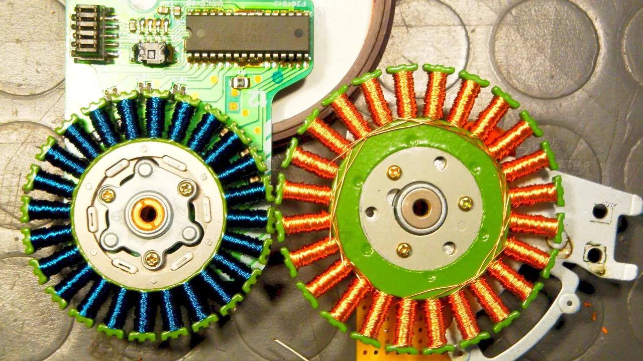
Brushless DC Motors and Brushed DC Motors explained - BLDC Fan (2)
1.7M
Brushed DC motors contain motor brushes, a commutator, and a rotor with multiple poles. The stator is typically a ring-shaped permanent magnet. When current flows through the rotor windings via the commutator, a second magnetic field builds up around the rotor. The commutator switches current between windings to ensure the rotor continues rotating by reversing the magnetic field direction at appropriate times. The interaction between the stationary stator field and the rotating rotor field creates the torque that drives the motor.
Click to watch →

Magnetic Effects of Electric Current | DC Motor - Parts and Working CBSE Class10 @Vedantu9_10
297.8K
A DC motor converts electrical energy to mechanical energy using direct current. The armature is the rotating coil on a soft iron core. The commutator reverses current every half rotation for continuous rotation. Carbon brushes maintain electrical contact with the rotating commutator. The field system creates the magnetic field using permanent magnets or electromagnets. The yoke provides mechanical support and carries magnetic flux.
Click to watch →
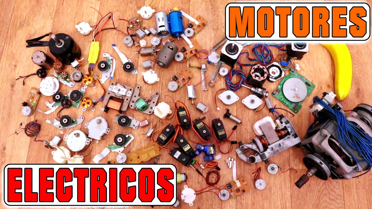
Tipos De Motores Eléctricos - DC/AC | Síncrono, Sin Escobillas, Stepper, Servo
178.7K
The brushed DC motor is the most basic motor type, commonly found in RC toys and DVD recorders. It consists of a stator with copper windings and permanent magnets, and a rotor with copper pads. Brushes (carbon contacts) switch power to different rotor coils as they spin, changing magnetic polarity to maintain rotation. Speed is controlled by adjusting voltage or using PWM. The motor can be modified with gearboxes for increased torque or dual shafts for additional components.
Click to watch →

Brushed DC motor இயங்கும் அடிப்படை விளக்கம்
3K
A brushed DC motor operates on the principle of electromagnetic induction, where current flowing through the armature windings creates a magnetic field that interacts with the permanent magnet field, producing torque that causes rotation; the brushes and commutator periodically reverse the current direction in the armature windings to maintain continuous rotation in one direction.
Click to watch →
Deep Dive
The distinction between Direct Current (DC) and Alternating Current (AC), and how electrical polarity affects components like LEDs.

299 का पहला वीडियो!/first video of 299
1.7K
Electrical supply comes in two types: AC (Alternating Current) and DC (Direct Current). DC supply maintains constant polarity - positive terminals always carry positive voltage and negative terminals always carry negative voltage. AC supply alternates polarity continuously, changing direction periodically. LEDs are polarity-sensitive components that require correct connection (positive to positive, negative to negative) to function. A 3.7V battery requires a 1kΩ resistor to safely power an LED. Understanding these fundamental concepts is essential before working on any circuit.
Click to watch →
Como Ligar um Led (ou um monte de leds) em AC - Tomadas e transformadores
33.9K
AC (Alternating Current) flows in both directions, changing polarity periodically, while DC (Direct Current) flows in only one direction. This fundamental difference affects how components like LEDs must be connected and protected in each type of circuit.
Click to watch →

Nie wieder flackernde LED Beleuchtung - Die Ultimative Lösung!
672
Alternating current (AC) periodically reverses direction, switching between positive and negative polarity every millisecond, like ocean waves moving back and forth. Direct current (DC) flows in one fixed direction with stable positive and negative terminals. Traditional incandescent lights work with AC because their resistance wire glows regardless of current direction. LEDs, however, are polarity-sensitive semiconductors that only conduct current in one direction, making them incompatible with AC without modification.
Click to watch →

【60分で全部復習できます!!】電流と電圧、オームの法則、電力・熱量、直流・交流、電流と磁界、電磁誘導、放射線、フレミングの左手の法則〔現役塾講師解説、中学2年、理科〕
569
Direct current (DC) flows in one direction with constant magnitude (like batteries). Alternating current (AC) changes direction and magnitude periodically (like household outlets). AC frequency is measured in hertz (Hz)—Japan uses 50Hz in East and 60Hz in West. LEDs have polarity: longer lead connects to positive, shorter to negative. With DC, only correctly connected LEDs light up; with AC, LEDs alternate lighting as current direction changes.
Click to watch →

【短時間で用語チェック!!】直流・交流・発光ダイオード〔現役講師解説、中学2年、理科〕
372
Direct current (DC) flows in one constant direction with constant magnitude, while alternating current (AC) periodically changes both direction and magnitude; LEDs require correct polarity (longer leg to positive, shorter leg to negative) to light up, so DC causes only one LED to light while AC causes both LEDs to light alternately.
Click to watch →
Deep Dive
The Law of Conservation of Energy, specifically how energy is converted between mechanical and electrical forms.

مراجعه الفصل الاول -الشغل والطاقه -فيزياء تانيه ثانوي ٢٠٢٦ الترم التاني |متبقاش جهاز
230.7K
Mechanical energy is the sum of kinetic and potential energy: ME = KE + PE. The law of conservation of mechanical energy states that ME remains constant in an isolated system. Energy can transform between forms: potential to kinetic (falling object), chemical to mechanical (car engine), electrical to light and heat (bulb). At maximum height, PE is maximum and KE is zero. At impact, PE is zero and KE is maximum. At midpoint, PE equals KE.
Click to watch →
Mechanics Part 6
11.1K
The law of conservation of energy states that energy cannot be created or destroyed, only transformed from one form to another. The total energy of an isolated system remains constant. Energy transformations include: chemical to electrical (batteries), electrical to light (light bulbs), electrical to mechanical (motors), mechanical to electrical (generators), and light to electrical (solar cells). These transformations demonstrate that energy changes form but the total amount remains constant.
Click to watch →

İş Güç Enerji +PDF | TYT Fizik Çek-AP 5 #çekap #tytfizik
237K
Energy transforms between forms: chemical to electrical (batteries), electrical to light (lamps), potential to kinetic (falling objects). The law of conservation of energy states energy cannot be created or destroyed, only transformed. In real systems with friction, mechanical energy decreases as it converts to thermal energy. The total energy remains constant, but mechanical energy specifically is not conserved when non-conservative forces act.
Click to watch →
RRB ALP CBT-2 Day-10 || Force, Work, Energy and Power | बल ,कार्य, ऊर्जा व शक्ति || By BK Pathak Sir
10.3K
The Law of Conservation of Energy states that energy cannot be created or destroyed, but it can only be converted from one form to another. The total energy in an isolated system remains constant. Examples of energy conversions include: electric heater (electrical → heat), electric bulb (electrical → light + heat), tube light (electrical → light), electric kettle (electrical → heat), microphone (sound → electrical), loudspeaker (electrical → sound), heat engine (chemical → heat → mechanical work), solar cell (light → electrical), chemical cell (chemical → electrical), and generator (mechanical → electrical).
Click to watch →

Science 28 : Work, Energy and Power || CDS - 1 2023
55.3K
The Law of Conservation of Energy states energy cannot be created or destroyed, only transformed. Total energy in an isolated system remains constant. Mechanical energy (PE + KE) is conserved when no non-conservative forces act. Examples: falling objects convert PE to KE, rising objects convert KE to PE. Everyday conversions include: bicycle (muscular to mechanical), food (chemical to thermal/mechanical), coal fire (chemical to heat), electric bulb (electrical to heat/light). This principle underlies all physical processes.
Click to watch →
Prerequisite Knowledge
- Concept 01Fundamental concepts of electromagnetism, specifically Faraday's Law of Electromagnetic Induction.
- Concept 02The basic construction and working principle of a standard brushed DC motor, including the armature, stator, commutator, and brushes.
- Concept 03The distinction between Direct Current (DC) and Alternating Current (AC), and how electrical polarity affects components like LEDs.
- Concept 04The Law of Conservation of Energy, specifically how energy is converted between mechanical and electrical forms.
Subsequent Learning
- Step 01Lenz's Law and the concept of electromagnetic drag, explaining why it becomes physically harder to rotate the motor's shaft as more electrical load is added.
- Step 02The design and mechanism of AC generators (alternators) and how they differ from DC generators through the use of slip rings instead of commutators.
- Step 03Real-world applications of motor-generator duality, such as regenerative braking systems in electric vehicles and wind turbine operations.
- Step 04Voltage regulation and rectification techniques used to stabilize and clean fluctuating generator output for sensitive electronic devices.
Motor as Generator
LED Setup
Glow Detection
Polarity Test
Direction Effect
Reverse Rotation
Motor as Generator
0:04Playing Section
- 1
DC motor acts as a generator when shaft is turned.
- 2
Mechanical energy rotates the axle to produce electricity.
Practical Limitations and Inefficiencies of DC Motors as Generators
While it is scientifically true that a standard DC motor can function as a generator, this educational demonstration overlooks critical engineering limitations. In real-world applications, using a DC motor for electricity generation is highly inefficient. DC motors rely on mechanical brushes and commutators to output direct current, which introduces significant friction, electrical arcing, rapid physical wear, and electromagnetic interference. Additionally, their internal windings are optimized for torque production rather than efficient power generation. For practical electricity generation, modern engineering heavily favors AC alternators or brushless generators combined with solid-state rectifiers. These systems eliminate the friction and maintenance issues of brushes while providing far superior conversion efficiency. Therefore, while the DC motor-generator setup is an excellent conceptual teaching tool, it is practically obsolete for viable power generation.
Deep Dive
Lenz's Law and the concept of electromagnetic drag, explaining why it becomes physically harder to rotate the motor's shaft as more electrical load is added.
Physics for Beginners
148.8K
Generators convert mechanical rotation into electrical energy through electromagnetic induction. Motors operate in reverse, converting electrical to mechanical energy. Lenz's law states that induced electromagnetic fields create currents opposing the original change in magnetic flux. This creates counter-torque opposing applied torque. Greater circuit resistance results in less current and less counter-torque, making generators easier to turn.
Click to watch →
LENZ'S LAW of Electromagnetic Induction | in HINDI
463.6K
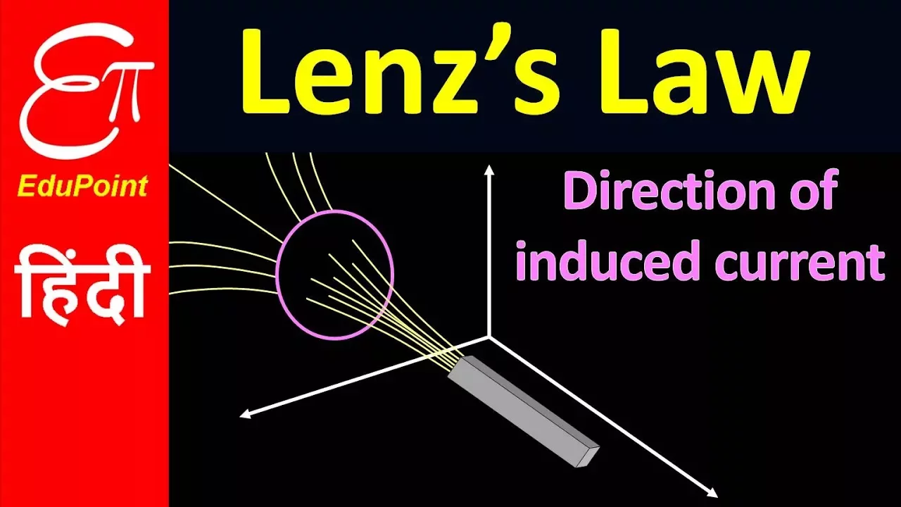
Lenz's Law states that the direction of induced current in a circuit is such that it creates a magnetic field that opposes the change in magnetic flux that produced it, which is a direct manifestation of the conservation of energy principle.
Click to watch →

विद्युत चुंबकीय प्रेरण - One Shot | Class 12 Physics Chapter 6 Electromagnetic Induction | BSEB
70.8K
Lenz's Law states that induced current opposes the change in flux that produced it. This is a consequence of energy conservation. Motional EMF occurs when a conductor moves through a magnetic field, causing charge separation. The formula is ε = vBL (for perpendicular motion) or ε = vBL sin θ (for angled motion).
Click to watch →

مسرحية الحث الذاتي للملف #تعليم #فيزياء #ثانوية_عامة
42.3K
Electromagnetic induction is the phenomenon where a changing magnetic field induces an electromotive force (EMF) in a conductor. When current flows through a wire, it creates a magnetic field that induces current in nearby coils. Lenz's Law states that the induced current always flows in a direction that opposes the change in magnetic flux that produced it. When current increases, induced current flows in the opposite direction; when current decreases, induced current flows in the same direction. The magnitude of induced EMF depends on the rate of change of magnetic flux - faster changes produce larger induced EMF. When current becomes steady, no induced EMF is generated because the magnetic field is no longer changing.
Click to watch →
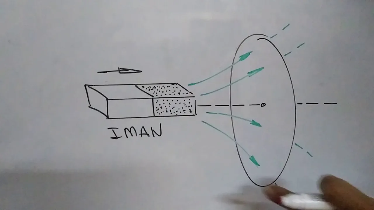
53. LEY DE LENZ #AnibalMalger #Física
60.5K
Michael Faraday discovered in 1831 that a changing magnetic field produces an induced current in a conductor. Lenz's Law states that the induced current creates a magnetic field that opposes the change in flux that produced it, demonstrating energy conservation. To apply Lenz's Law, consider two instants to observe flux change. There are only two cases: when flux increases, the induced field opposes the external field; when flux decreases, the induced field supports it. The right-hand rule determines current direction: thumb points in the induced magnetic field direction, fingers curl in the current direction. Common scenarios include a coil entering a magnetic field (flux increases, counterclockwise current), leaving the field (flux decreases, clockwise current), or moving away from a current-carrying wire (flux decreases, supporting current). No induced current occurs when flux is constant.
Click to watch →
Deep Dive
The design and mechanism of AC generators (alternators) and how they differ from DC generators through the use of slip rings instead of commutators.

SSLC Physics | Electromagnetic Induction in Daily Life | Oneshot | Exam Winner
97.4K
AC and DC generators have the same basic components: field magnets, armature, and brushes. The key structural difference is in the commutator: AC generators use slip rings (full rings), while DC generators use split rings (segmented rings). Slip rings allow continuous AC current flow, while split rings convert AC to DC by reversing connections at each half-cycle. In both types, the current induced in the armature is always AC. The difference is in the output: AC generators deliver AC directly, while DC generators convert the AC in the armature to DC using the split ring commutator. For a DC generator to produce DC output, the armature must be rotated while the field magnets remain stationary. If the field magnets are rotated instead, the output will be AC.
Click to watch →
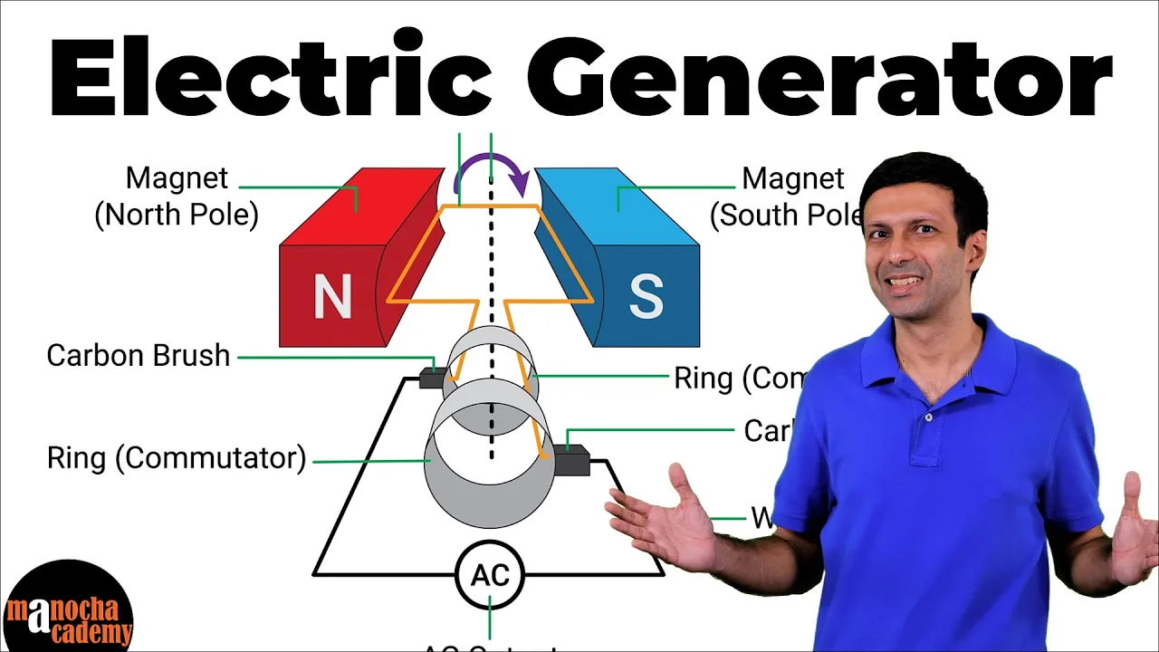
Electric Generator
182.8K
An electric generator is a device that converts mechanical energy into electrical energy through electromagnetic induction, where a rotating coil in a magnetic field induces an alternating current (AC) that continuously changes direction; the generator consists of a rectangular coil, magnetic field, slip rings, and carbon brushes, and differs from a DC generator by using slip rings instead of a commutator to produce AC rather than DC.
Click to watch →

فيزياء السادس علمي || المراجعة المركزة الاقوى || جميع كلاميات الفصل الثاني وبالتفصيل
1.2M
An electric generator converts mechanical energy into electrical energy using electromagnetic induction. An AC generator consists of a coil rotating in a magnetic field, with slip rings and brushes to collect the induced current. The induced EMF varies sinusoidally with time. A DC generator uses a split-ring commutator instead of slip rings to produce unidirectional current. The induced EMF in a generator is given by ε = NBAω sin(ωt), where N is the number of turns, B is the magnetic field, A is the area, and ω is the angular velocity.
Click to watch →
MAGNETISM II PHYSICS II SSC CGL, CHSL, GD, MTS, CPO, RRB NTPC, PSC #physics
1.3K
AC generators use slip rings to collect alternating current, while DC generators use split rings (commutators) to convert AC to DC. The commutator reverses the connection every half rotation, ensuring current always flows in one direction through the external circuit. Both generators have similar construction with a rotating coil (armature) in a magnetic field.
Click to watch →

الفصل الثاني الحث الكهرومغناطيسي تصوير جديد المحاضرة 22
92.1K
The key difference between AC and DC generators lies in their current transfer mechanisms. AC generators use two slip rings that allow current to flow in alternating directions, producing AC output. DC generators use a single split-ring commutator (two insulated halves) that reverses connections at the right moment, producing DC output. The commutator ensures current always flows in one direction through the external circuit, making it suitable for applications requiring unidirectional current.
Click to watch →
Deep Dive
Real-world applications of motor-generator duality, such as regenerative braking systems in electric vehicles and wind turbine operations.

Motor Generator Unit Explained {Science Thursday Ep160}
3.2K
A motor generator unit is a single device that can function as both a motor (converting electrical energy to mechanical motion) and a generator (converting mechanical motion to electrical energy), operating on the fundamental principle that motors and generators are essentially the same device at the physics level; this dual functionality enables critical applications including regenerative braking in electric vehicles, integrated starter-generator systems in modern vehicles, dynamic braking in trains, pumped hydro energy storage, and thermal energy recovery systems in high-performance engines.
Click to watch →
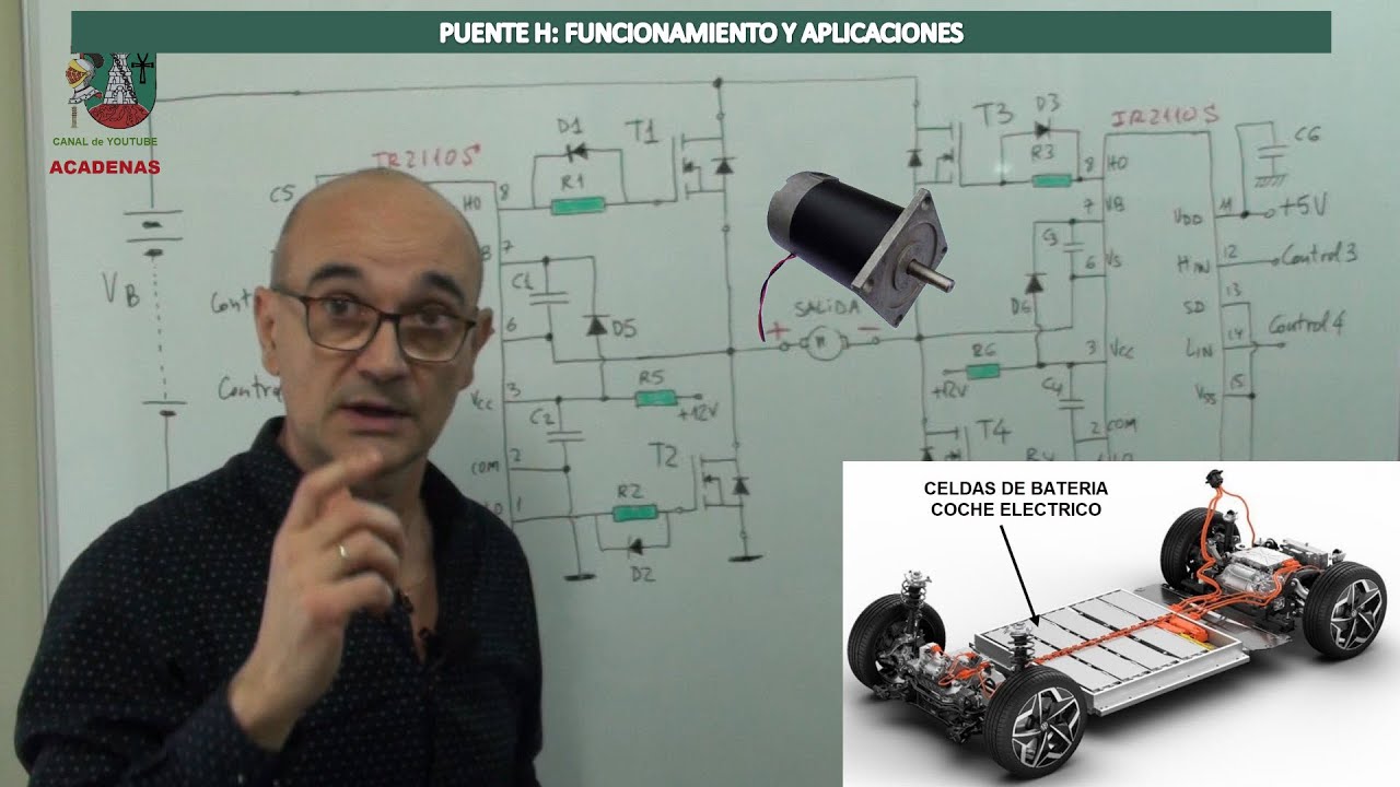
Puente H: Funcionamiento y aplicaciones (Clase 119)
58.1K
Motor braking is achieved by stopping the applied voltage while maintaining a path for the motor's inductive current. When transistors T1 and T4 conduct, the motor runs in one direction. When turned off, the motor's inductive current cannot stop instantly and finds a path through freewheeling diodes, creating a braking effect. Regenerative braking is achieved by turning off all transistors, allowing the motor's inductive current to flow back through the freewheeling diodes to the battery, effectively charging it. This principle is used in electric vehicles - when braking, the motor's kinetic energy is converted back to electrical energy and stored in the battery. A DC motor can function as a generator when mechanical energy is applied to rotate it, inducing a voltage that generates current in the opposite direction, creating a braking torque.
Click to watch →
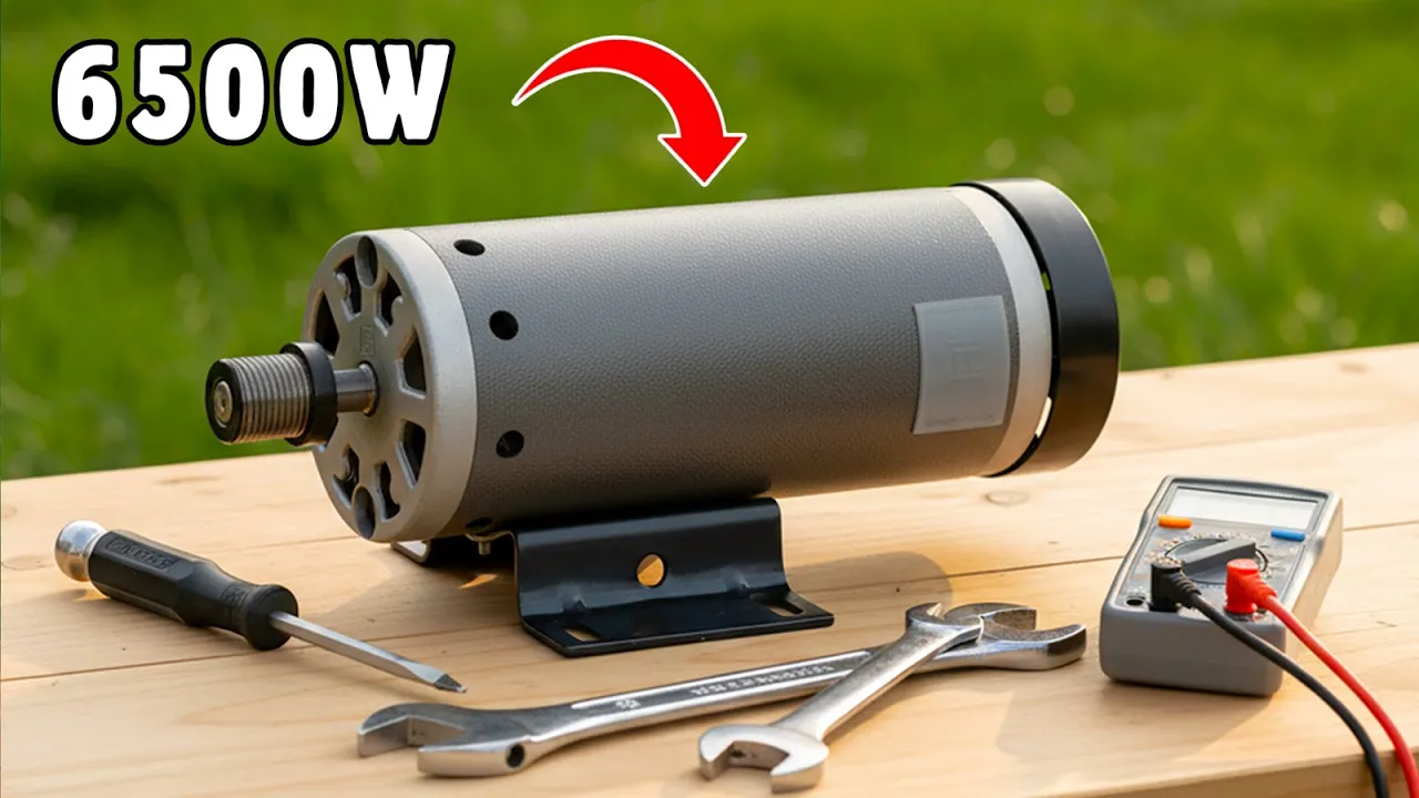
Regenerative Braking Power Generation System | Electricity Without Fuel
5K
Electric motors can operate as both motors (converting electrical to mechanical energy) and generators (converting mechanical to electrical energy). Permanent magnet motors are particularly suitable for regenerative braking because their fixed magnets create consistent magnetic fields for energy conversion. Testing involves connecting a multimeter to measure generated voltage when the motor shaft is rotated manually, demonstrating the bidirectional energy conversion capability essential for regenerative braking systems.
Click to watch →

Самый Простой Вечный Двигатель
158.6K
This segment demonstrates the dual nature of motors as both motors and generators through hands-on experiments. The presenter shows that when motor wires are short-circuited, the motor resists rotation significantly, as if a brake has been applied. This occurs because the short circuit creates a magnetic field opposing rotation. The presenter then demonstrates that the same motor can generate electrical energy when mechanically driven, outputting approximately 12 volts and 250-700 watts. This illustrates the fundamental principle that motors and generators are essentially the same device operating in reverse.
Click to watch →

Галилео. Эксперимент. Генератор-двигатель
226.7K
The same electromechanical device can function as both an electric motor and a generator depending on how it is used. When electrical energy is applied to the device, it operates as a motor converting electricity to mechanical rotation. When mechanical rotation is applied to the device while its electrical terminals are connected to a load, it operates as a generator converting mechanical energy back to electrical energy.
Click to watch →
Deep Dive
Voltage regulation and rectification techniques used to stabilize and clean fluctuating generator output for sensitive electronic devices.

EV YAPIMI BASİT VE VERİMLİ JENERATÖR YAPIMI - VERİMLİ JENERATÖR NASIL YAPILIR -EVDE ELEKTRİK ÜRETİMİ
212K
Single diode rectification creates half-wave rectification, capturing only one half of each AC cycle. For improved efficiency, multiple diodes can be connected to create full-wave rectification, utilizing both halves of the AC waveform. A capacitor connected in parallel stabilizes voltage and smooths fluctuations, particularly important at low rotation speeds where output may flicker. The capacitor's positive terminal connects to the positive output, and negative to the negative output. These techniques transform the generator's raw AC output into stable, usable DC power suitable for powering electronic components.
Click to watch →

Clase 02 Análisis de la Fuente de alimentación del Aire Acondicionado | refriserka
15.1K
Bridge rectifiers convert AC to pulsating DC using four diodes, each with 0.7V forward drop. The resulting pulsating DC contains voltage variations that create ripple. Capacitors smooth this ripple by charging during voltage peaks and discharging during valleys, producing more stable DC output. Voltage regulators (7805 for 5V, 7812 for 12V) provide stable output regardless of input variations. Proper capacitor selection requires voltage ratings exceeding circuit voltage to prevent catastrophic failure. This systematic approach ensures clean, stable power delivery essential for sensitive electronic components like microcontrollers.
Click to watch →

How to Test a Regulator Rectifier - They're Not all the Same! | 3 Phase Rectifier Test | Partzilla
636K
The voltage regulator rectifier converts AC stator output to DC battery charging voltage (12.8-14.2V). Full wave rectification flips AC sine waves to create continuous positive DC, smoothed by capacitors. Diodes act as on/off switches: forward bias allows current flow (~0.48-0.52V drop), reverse bias blocks it. Testing requires a digital voltmeter with diode function. Honda units allow complete diode testing by forward and reverse biasing all six diodes sequentially.
Click to watch →
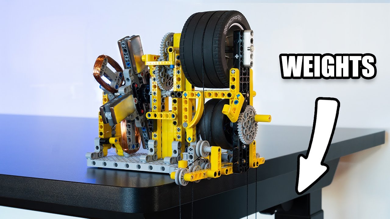
Lego Gravity Power: Turning Falling Weights Into Electricity!
452.6K
Full bridge rectifiers convert three-phase AC generator output into smooth DC power suitable for powering electronic devices. The video connects a three-phase full bridge rectifier to combine outputs from all three generator coils, producing three times the current of a single coil. This electrical circuitry enables the generator to power devices requiring direct current, such as LED lights and small motors, by eliminating the alternating nature of the generator's raw output.
Click to watch →

БЛОК ПИТАНИЯ СВОИМИ РУКАМИ. Трансформатор, диодный мост, стабилитрон -- объясняем просто и доступно!
575.9K
Diode bridge rectifiers convert AC to pulsating DC using four diodes arranged so current always flows through two diodes regardless of AC polarity. Critical specifications include Peak Inverse Voltage (PIV) and forward current rating. After rectification, output contains ripple voltage requiring filtering. Multimeters display RMS values (~0.707 × peak), but capacitors charge to true peak voltage—requiring proper voltage rating. Zener diodes maintain constant voltage by dramatically reducing resistance when reverse-biased voltage exceeds breakdown voltage. They require series current-limiting resistors because their breakdown resistance is very low. The emitter follower configuration provides current gain while maintaining voltage level, allowing a small Zener reference to control larger load currents. The base-emitter junction has a ~0.6V drop, so a 5.9V Zener provides ~5.3V output. This combination solves the current limitation problem of direct Zener connection while providing stable voltage regulation.
Click to watch →
Motor as Generator
LED Setup
Glow Detection
Polarity Test
Direction Effect
Reverse Rotation
Motor as Generator
0:04- 1
DC motor acts as a generator when shaft is turned.
- 2
Mechanical energy rotates the axle to produce electricity.
Practical Limitations and Inefficiencies of DC Motors as Generators
While it is scientifically true that a standard DC motor can function as a generator, this educational demonstration overlooks critical engineering limitations. In real-world applications, using a DC motor for electricity generation is highly inefficient. DC motors rely on mechanical brushes and commutators to output direct current, which introduces significant friction, electrical arcing, rapid physical wear, and electromagnetic interference. Additionally, their internal windings are optimized for torque production rather than efficient power generation. For practical electricity generation, modern engineering heavily favors AC alternators or brushless generators combined with solid-state rectifiers. These systems eliminate the friction and maintenance issues of brushes while providing far superior conversion efficiency. Therefore, while the DC motor-generator setup is an excellent conceptual teaching tool, it is practically obsolete for viable power generation.
Fundamental concepts of electromagnetism, specifically Faraday's Law of Electromagnetic Induction.
The basic construction and working principle of a standard brushed DC motor, including the armature, stator, commutator, and brushes.
The distinction between Direct Current (DC) and Alternating Current (AC), and how electrical polarity affects components like LEDs.
The Law of Conservation of Energy, specifically how energy is converted between mechanical and electrical forms.
Lenz's Law and the concept of electromagnetic drag, explaining why it becomes physically harder to rotate the motor's shaft as more electrical load is added.
The design and mechanism of AC generators (alternators) and how they differ from DC generators through the use of slip rings instead of commutators.
Real-world applications of motor-generator duality, such as regenerative braking systems in electric vehicles and wind turbine operations.
Voltage regulation and rectification techniques used to stabilize and clean fluctuating generator output for sensitive electronic devices.
41.7K views316likes2:39@ABC123XYZOriginal Release: 2016-09-28
the DC motor is a readymade generator that will generate electricity all that you have to do is turn the axle of the DC motor using a mechanical outside source of energy to show that I have a DC motor and few LED bulbs let's see how it is working here I am connecting four LED bulb in a row two green bulb and two blue LED bulbs are connected in the same polarity let me rotate the axle of the DC motor LED bulbs are glowing now for testing I am connecting two blue bulbs in specific polarity and two green LED bulbs in reverse polarity let's see what's happening when I rotate the shaft yes now when the shaft rotate on clockwise two LED bulbs will be on due to forward bias and other off due to reverse bias and vice versa in case of anticlockwise rotation the DC motor is a readymade generator that will generate electricity all that you have to do is turn the axle of the DC motor using a mechanical outside source of energy
Up Next

17:06
Wind Turbine on a Vehicle: Feasibility & Aerodynamics 1
@QuintBUILDs
270.1K views•2020-06-22

30:32
Ultrasonic Transducers: Resonant Frequency Measurement and Horn Design
@imajeenyus42
229.9K views•2017-02-22

54:16
Polymer Environmental Degradation: Mechanisms & Stabilization
@iit
1.8K views•2012-07-10

33:39
How a Student's Question Saved a NYC Skyscraper from Collapse
@veritasium
22.8M views•2025-04-26
Related Study Plans & Knowledge Roadmaps
Structured learning paths in Engineering
engineering
Building Acoustic Levitators: Physics & Arduino
01The Physics of Sound and Standing Waves
02Piezoelectric Transducers and H-Bridge Drivers
03Arduino Programming: Generating 40 kHz Signals
+ 2 more learning modules
14h5 modules
Explore Roadmap
engineering
Building Peltier Cloud Chambers: Particle Tracks
01Cosmic Rays & Cloud Chamber Physics
02Thermoelectric Cooling (TEC) Fundamentals
03Custom Liquid-Cooling Loop Design
+ 2 more learning modules
18h5 modules
Explore Roadmap
engineering
Yagi-Uda Antennas: Modeling, Build & VNA Test
01Introduction to RF and Antenna Fundamentals
02Yagi-Uda Antenna Design Principles
03Antenna Modeling and Simulation in 4NEC2
+ 2 more learning modules
18h5 modules
Explore Roadmap
engineering
ECG Monitor Design: Op-Amps, Filters & Noise
01Electronics & Breadboard Basics
02Op-Amps and Instrumentation Amplifiers
03Bioelectricity and ECG Fundamentals
+ 2 more learning modules
18h5 modules
Explore Roadmap