











![Skytech [Custom]er Build Stream 07.7.26](https://i.ytimg.com/vi/GHWLJPF5LgM/maxresdefault.jpg)
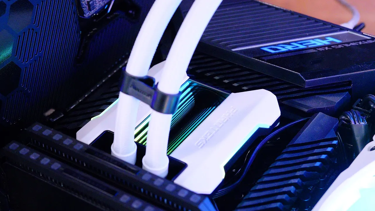






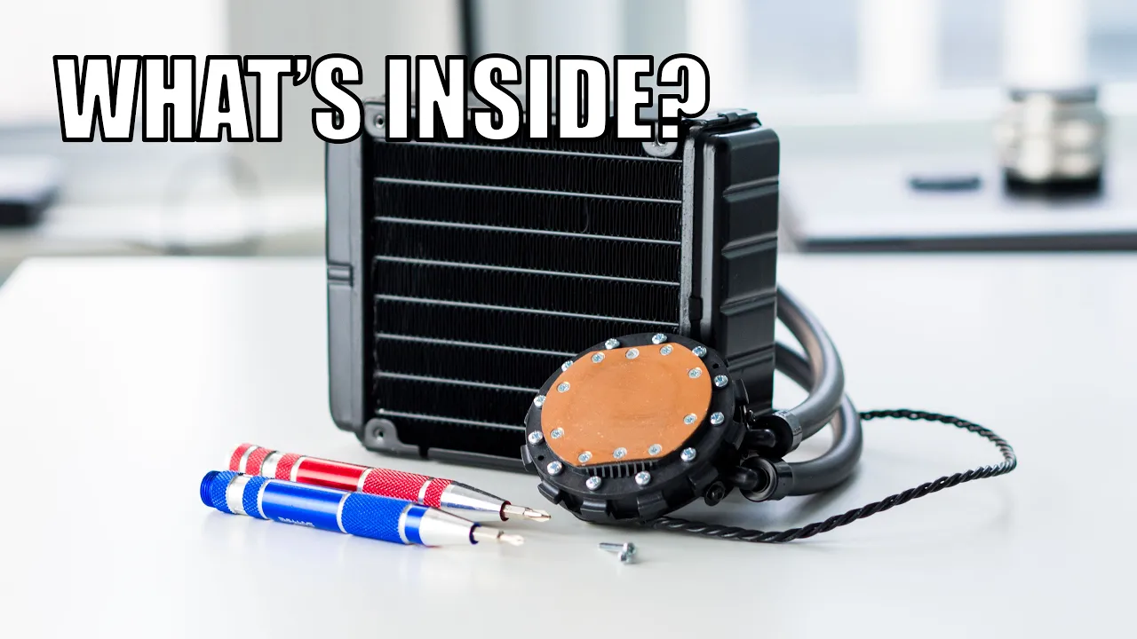
The Arctic Liquid Freezer III CPU cooler features a modular design with a separable VRM fan unit, a larger metal impeller, and taller microfins (approximately 1mm taller than the previous generation) that improve thermal performance; the coldplate uses leaf springs that create a central pressure bump during mounting, which explains pressure distribution anomalies seen in laser scanning tests.
Arctic Liquid Freezer III Teardown: Design and Repairability Analysis
Added:Fundamentals of All-in-One (AIO) Liquid Cooling: Understanding the basic components, including the pump, cold plate, radiator, tubing, and fans, and how they work together to dissipate heat.
Principles of Heat Transfer: Core concepts of thermal conduction (from the CPU to the cold plate) and convection (fluid transporting heat to the radiator), including how surface area affects cooling efficiency.
Anatomy of a Cold Plate: Familiarity with the purpose of micro-fins in cold plates to increase surface area contact between the metal and the coolant.
Common AIO Failure Modes: Basic knowledge of issues like galvanic corrosion, permeation, pump degradation, and sediment buildup that typically limit the lifespan of liquid coolers.
Thermal Benchmarking Methodology: How to design and execute scientific thermal performance tests to measure the real-world impact of design changes like taller micro-fins.
AIO Maintenance and Repair Protocols: Practical steps for safely opening, cleaning, refilling, and resealing repairable liquid cooling loops to extend their lifespan.
Fluid Dynamics in Thermal Engineering: Advanced study of coolant flow rates, pressure drops across micro-fins, and the boundary layer effect in micro-channels.
Material Science in Cooling Systems: Exploring the chemical interactions between different metals (copper and aluminum) and the role of specialized coolants and biocide additives in preventing corrosion.
372.6K views10.4Klikes23:24Original Release: 2024-02-21
just going to get us banned oh like a like some kind of weird dystopian fisherman uh okay he once we have a fun tear down of the liquid freezer 3 today we have a full review of this on the channel it just went live I think yesterday at the time this video goes up this is going to be a more in-depth investigation into why some of the behaviors were the way they were when we did things like the pressure testing like the 3D scan uh where we saw basically the only true weak spot of the cooler overall we said it's the best cooler that we've tested uh for noise normalized thermals period and we did make a recommendation for it however this tear down is going to look into some of those short comings but also try to evaluate what's changed because if you look closely at this pump Block versus the original liquid freezer 2 which we have torn apart here from uh many years ago the assembly is massively different uh and so the first thing we're going to look into is how they've changed the actual impeller and the housing of where the liquid flows because that potentially contributes a lot to the thermal characteristics depending on if they've widened those channels to allow more water to pass through more efficiently uh maybe they've changed the microfin density that's what we're going to be looking at today and additionally I really want to get in there to see if there's any type of deflection where when you torque those screws down is it apply line of pressure that causes that sort of central bump we saw in the laser scan so we're going to take this apart and have some fun learning about how it's built before that this video is brought to you by thermal Grizzly and the cryos sheet graphine pads these cryo sheets are molecularly stacked in the z-axis to encourage vertical direct thermal transfer from the IHS to the cooler cryos sheet pads are made to be easily applicable for a thermal interface and completely avoid paste dry out because it's not paste it Mak makes them particularly useful for lawn service life systems with minimal maintenance they come in multiple sizes for suitability on the most common laptops and desktop CPUs and you can learn more at the thermal Grizzly cry sheets at the link in the description below first thing I want to do is a couple Loose Ends we had where in the review we're already at 30 minutes so I was like you know let's leave a couple of these things for the tear down and one of them is going to be the sizing of this cold blate about 40 mm by about let's call it 44 and let's look at one of the original this is the the actual OG that we reviewed I think you can tell it's even patined a little bit this one hasn't been used in years so so 44 that's the same and 40 so it's a same size cold plate uh it doesn't mean anything about the micro fins though so we'll still need to look at that so for the blocks these are obviously very different not going to spend a ton of time explaining to you how they're different you can look at it the biggest change though is the pump cap which we've already detailed heavily in that review and this is kind of interesting because first of all from a repairability standpoint the uh option of just pulling off the entire vrm fan which is the most likely part to fail tiny fans are always the most susceptible vulnerable to long-term failure from things like dust stuff like that they just don't have the power to really push past it they'll burn out uh but being able to replace the entire unit is a lot more user friendly without a huge amount of extra waste certainly less than shipping the product back and forth makes it a lot more repairable maintainable which is a good thing in theory if they wanted to later maybe sell uh detachable alternates or something I don't know if they're planning that but it was the first thing my mind uh being in the gaming World jump to was how can this become DLC the impeller I'm thinking is going to be in here it's the only thing really large enough to hold it and it's kind of interesting the the liquid flow is going to get pushed down here over the micro fins I'm going to start with the actual cooling part uh cuz I really want to look at that impeller and the micro fins and we've got an old plate here disassembled from one of our repair kits previously and we'll use this for comparison against the new and this one's got a I was going to say a little bit we're going to go with a lot of bit of G on it okay so today we're going to be working on our soldering mat you can grab this on store. Gamers X it's not that if you want a highly rugged and high heat resistant surface for soldering projects model building uh doing mechanic or other work that you want a a rugged surface to work on plus a bunch of tool holders and component holders so um start with a a quick kind of overview of the anatomy of a liquid cooler and the component just to get everyone up to speed this is the cold plate the cold plate has micr fins on the other side this uh well this is the leaf sprain specifically this is not um standard you get inlets and outlets in there that are made within the plastic shell the plastics for liquid coolers can typically handle about 60° C for specifically the liquid temperature that sounds low when you consider that this is contacting something that might be closer to 90° Cel or 70 80 whatever it may be but the liquid temperature runs way lower than the surface temperatures of these things uh so 60 is pretty standard I don't know what arctic's specific rating is for their Plastics I do know that aitech though um starts to starts to fail at 60° C my understanding is that's pretty common as a temperature or plus or- 5° uh there's almost always a PCB with these that's down on the pump block the complexity of the PCB depends on presence of things like RGB LEDs and uh LCDs other functionality they might have pcbs typically have soldered in wires that are not separable from uh the board without desoldering them or cutting them and then after that we run into of course the tubes now these tubes there's typically two common types there's a a more rubberized one which is what this is the benefit of the rubberized tube is that it's more flexible than the than the alternate that we'll talk about uh the downside is a little bit more permeation over time where the liquid will permeate those tubes so you have some natural liquid loss typically it's uh about five six years for anything serious to be lost and maybe need a top up the other type of tubing is a hard corrugated Teflon lined tubing that's what Cooler Master uses we'll show some old examples from the sidon series that one's more resistant to permeation and loss of liquid but it's much more rigid and if it cracks and you have worse problems inside of the actual uh barbs the this area of where the tubes connect to the rest of the body normally there's like a piano wire that kind of holds it and secures everything those come up to the radiator we have an old 3D animation that shows how these work but this has a split channel in it the liquid goes in one side comes out the other side so you have all you can think of it as a hot and a cold side and then the radiator itself this one's a thicker radiator I think this is a 38 millimeter so this is the outer shell of the rad just measure it there it's 35 if you measure it at the bump it's 38 but the actual inner part of the radiator is a little thinner than that still this is thicker though that's a large part of the performance that Arctic has but let's start with just draining it I'm going to try and do this non-destructively we'll see sometimes it's kind of hard okay there's our cold plate that is nice and new you can see the difference in the uh the Gen one this is the one we replaced after they contacted us about uh some of the the units being in a bad badge so the gasket immediately this looks pretty different um this would have been the original original gaset and we'll compare these once they're both out but that already is a different style to it let's pull that out which not surprising cuz I think the gasket choice uh definitely has a lot to do with the um debris build up in a loop so that was mounted like that I think and then we're going to drain this water out um I don't have a bucket nearby so this one actually might be kind of challenging to drain just because it's got that angle in it just going to get us banned so the liquid uh for basically any liquid is going to okay there was still some more in there typically liquid is a propylene glycol uh the higher percentage of distilled water the better the propylene glycol is used for a couple scenarios but one of them is kind of a natural resistance to um to corrosion debris buildup another one is actually shipping so it gives a a better range for the freezing point and you put it up uh in colder environments then that'll that'll kind of uh increase the range that the cooler is viable or can be stored and shipped in I've seeing two clear channels in here we'll try and pick this up on the camera but uh there's one channel down in there so that actually you can see it right here this piece that's a channel and then right next to it is another one so these are going out ultimately to the tubes through the impeller area um you can see that flow guidance here so let's compare this to the original I have one taken apart here unfortunately I don't think I have the impeller with this one but we have some old b-roll of it so you see the channels the design here is massively different uh where previously you had this kind of slope in and over here as well uh hit the impeller and the cold plate was actually mounted up up here higher up kind of closer to the camera so very different internal chamber uh let's take a closer look at the important part down here the actual micro fins and sort of despite the agent appearance of our old one here um see if they have any similarities F areas about 21.6 28.8 4 now there's a vertical component to that too so we actually can't do the area calculation obviously from something that's simple but so I mean that's the same functionally it's also the same okay uh I don't know that the density has changed we'd have to put under a micr scope and count the vertical would be interesting to know though all right it's like 3.5 or so this one yeah it's definitely shorter I just make sure maybe they change the Milling around the channel yeah okay that's kind of a crazy height difference it's about 1 mm and that's going to contribute in a big way because more surface area so for each of those fins now millimet taller um I'll go put these under a microscope to check the fin density as well but the height alone is going to contribute a lot to the cooling capabilities of this um more potential to get heat into the cold plate efficiently and get it out uh into the through the liquid into the radiator of course so big change there um additionally if you look closely at these they have changed the sort of channeling so they're they're chewing into more of that surrounding copper it's the same overall size as we saw earlier but if you look on either side of this micr fin stack they've got some channeling around it whereas on the old one it was only uh from current orientation towards the camera and towards me where we had the the channels there U so that is another change now how specifically that manifests in performance I can't tell you uh you really would only be able to tell that from simulations cuz we can only kind of look at it holistically for performance but uh another big change on the last I think that height is the largest difference we're seeing though uh you can see the differences here as well in the design where they've changed the actual shape of where the water's going to hit and get diverted into it and then now on this one there's this kind of curvature up on the the lip over here so anyway that's the design of the cold plate I'm just going to start removing screws until we find what we want so that you might be able to do a a fill there with like a syringe or something but I would honestly I would just take the C plate off and fill with the bottle from the bottom that's what we normally do okay let's remove more screws we're going to remove the PCB here that's going to give me the best access wow it's in there all right that is all three screws for the PCB and see if that is loose yet some coar threaded screws hidden down the side it's actually I think that's the same Screw As what the PCB was using got two more back here FAL is about to witness a stabbing over here there's another screw down there we can get it that's good okay all right right okay so that cover that screw just goes to a plastic back cover there is nothing to discuss here of Interest this is so many screws this is a a liquid cooler that has probably some of the highest count of screws I've worked on I won't be able to really comment on if that's good or bad until we get in there the most important thing is it doesn't leak so okay we're getting somewhere cool it might be possible to non-destructively disassemble this there's the impeller that is a large impeller they had a large one with the old model too with the and magnets and wet oh like a like some kind of weird dystopian fisherman uh okay we've made it to the interesting part massive impeller this is the direction that these aios clc's have been going so EK also did this the original liquid freezer used a relatively for the time large impeller too and a metal one which also is uh all a big improvement over what used to dominate the market and that was acch tiny yellow plastic three praed impellers that uh were just generally impotent so this is this is a a quality impeller by modern standards it's so a larger sizing it's more durable than what we saw from the old plastic designs so this is good this is what we want to see so that's it for that that is a completely metal part that should effectively be uh indestructible so here's the motor down this is what fell out of that housing a second ago see the back side of the same prob points we talked about earlier and otherwise just the the back side of the PCB nothing too interesting here um now when I was inspecting this for a moment off camera I had a a brief moment of stupidity normally they're much longer cuz sometimes you can see the date on these things to figure out when they went into production and I saw this and I was like it was made in fanuary which is not a month so here we can see the other side of the channeling where we're going to have some liquid flow uh and that's maybe the closest comparison so you can see some some similarities there but uh definitely a drastically different design and so kind of recapping big changes that we've seen here uh the impeller remains uh this is still a high quality metal impeller the micro fins had big changes it's about a millimeter taller on the fins and some channeling differences which again we don't have the the capabilities you really would need software simulation or something to understand the impact of of the channeling changes um however they are different in large ways and we know that the cooler is better so they are different in better ways the easy deductive reasoning there the motors also have differences so um I don't know off the-shelf Motors I I'm not familiar with kind of uh prefab options on the market this is an area that I would like to learn more about um but anyway they are different just playing a game of Spot the Difference and that's about the the most Insight I can offer there so unfortunately no value to add on that front for the rest of this so uh this was true of the old one too but for the most part but you can non-destructively remove this PCB which is nice this could all go completely back together and still work so that's nice to see it would be relatively easiest for us to refill it uh it remains a functional unit without destroying anything sometimes we have to destroy liquid coolers to actually take them apart um at least reasonably without desoldering a bunch of stuff so that's good to see uh other times too you'll see companies tie in um the actual the copper wraps here to the pcbs in a way where they have to be separated to take it apart further and that just involves basically destroying it until again you want to resolder it in or something so from repairability and access standpoint I like how this is assembled this would be very easy to to completely go and change out Parts if you ever needed to let's do the last piece here which is just going to be this uh vrm fan I just want to see what they're using for the fan Supply itself so let's take these out uh these are just magnets those contact the screws on top of the leaf spring oh cool the cable's actually okay instead of soldering that in they're just attaching it so um this is where you for example I guess you'd connect for well first of all the pads are here so that's where we're getting our power um through sort of the the rest of the unit and then if you had an RGB pump cap it would go here as well which maybe is part of their concept again I I don't I'm I guess I'm cynical I always look at things like I said for DLC and definitely could see this particular piece being a thing that you just Swap this for different designs on top or something uh but anyway this is not actually a fan it doesn't spin I we talked about that in the review I still saw comments that were confused about it the fan is here much smaller than that top cap uh it's got some more depth to it so this is um this is the squirrel cage style fan in terms of area you can see that there's good coverage area out this side it's going to kind of spew air that way you get some out this way this way this way and there's like one dead spot we showed in the review a little bit here and then it just ends short back here so it's focusing that air flow in the North and the west of the motherboard okay so that's the tear down couple thoughts here first of all this was extremely easy to work with so as I said uh know if it got left in the video or not but uh some of the liquid coolers have taken apart over the years actually a lot of them it really requires either extreme patients where you're going to be desoldering things to get certain pcbs out get the motor out stuff like that or you're going to be cutting them which is destructive and there kind of your two options this was entirely held together with screws it's a lot of screws more than I'm used to working with for liquid cooler however we didn't have to make any cuts to things we didn't have to desolder anything so each individual component was able to come out in a way that's individually serviceable so if you had a specific failure or more likely if you sent the unit in and Arctic wanted to do a repair rather than just throw it away and replace it each part can be individually repaired assuming they want to do it that way I don't know how they handle their rmas uh if there's an unknown failure but that's a good thing and that means that you would be able to do such repairs as well if you had uh a supply of a known good part the impeller remains high quality so they've stuck with the larger size impeller that has uh it's all metal and like I said in the rest of the Teran out it's these are basically Invincible compared to some of those older cheaper plastic ones the micro fins are way different so that height difference is going to be huge for the Coolin performance the radiator thickness is the other large aspect of that it's larger than the typical radiator thickness is so they've got a lot going for them in terms of cramming in more surface area uh fitting the housing around that new height and then they're going to have to deal with things like new flow restrictions um impedance to flow and trying to min max for pressure versus flow um and again simulation wise that's where you'd see kind of all the outcomes for that because there's some changes to the channeling but in thermal performance which is what we test holistically it is objectively better than liquid freezer 2 so it's working what they're doing here uh and it's better than basically everything else on the market roughly tied with the Mystique 360 when noise normalized um and way more noise efficient when they're at 100% speed so arctic's doing well with this I thought the disassembly was extremely easy quality of Parts was good overall definitely a weird shape with that sort of L shape to it actually that was the last thing I wanted to look at I'd forgotten about that this was is actually one of the goals of today's tear down uh we saw in that laser scan and the pressure map that there was that one section about 8 mm in from the top of the motherboard where there was just a channel that was kind of missing pressure but it was really high pressure centrally and all the pressure scans that we did and this Leaf sprain kept me kind of curious so what I just did is screwed into a contact frame except without the cold plate in it and we'll have to take a Beal shot of this cuz it's extremely subtle but in here you can actually see a curvature it's basically convex going up centrally where that spring I think is applying some pressure and pushing up there which uh the that would manifest uh if I understand it correctly is it would um sort of depending on your perspective I guess to press this inward centrally as well creating that higher pressure area of contact centrally and also accounting for that missing channel that we saw I think that is the intended design in theory their reason for doing this would be to use the pressure centrally to then flatten the cold plate once it's in contact with the IHS from the other side which we can't see uh from from this perspective however in practice what we saw at the pressure map was that it indicated even if the plate is flat the pressure is no longer even as a result of this mounting style but at least now we have an explanation for why it's happening where it's specifically and it's clearly intentional design leaf springs pushing centrally applying that pressure and bowing it and uh that gives us an answer so we have some more insight now because if we wanted to we could throw this on the laser scanner do it again with it assembled and um and really prove it but maybe in a separate piece that's it for this one thanks for watching as always to support our work go to store. Gamers x.net grab one of the solder mats that I worked on not only is it extremely heat resistant it's also water resistant it's been there this whole time so you can grab one of those on the store also grab one of our tool kits or our mod mats which is under this and subscribe for more we'll see you all next time
Up Next

63:42
Pump Curves & System Curves Explained | HVAC Engineering Tutorial
@HVAC-TV
16.2K views•2023-01-17

30:32
Ultrasonic Transducers: Resonant Frequency Measurement and Horn Design
@imajeenyus42
229.9K views•2017-02-22

26:05
Noctua NH-P1 Passive CPU Cooler Review: Benchmarks & Schlieren Imaging
@GamersNexus
401.7K views•2021-06-29

33:39
How a Student's Question Saved a NYC Skyscraper from Collapse
@veritasium
22.8M views•2025-04-26
Related Study Plans & Knowledge Roadmaps
Structured learning paths in Engineering
engineering
Building Acoustic Levitators: Physics & Arduino
01The Physics of Sound and Standing Waves
02Piezoelectric Transducers and H-Bridge Drivers
03Arduino Programming: Generating 40 kHz Signals
+ 2 more learning modules
14h5 modules
Explore Roadmap
engineering
Building Peltier Cloud Chambers: Particle Tracks
01Cosmic Rays & Cloud Chamber Physics
02Thermoelectric Cooling (TEC) Fundamentals
03Custom Liquid-Cooling Loop Design
+ 2 more learning modules
18h5 modules
Explore Roadmap
engineering
Yagi-Uda Antennas: Modeling, Build & VNA Test
01Introduction to RF and Antenna Fundamentals
02Yagi-Uda Antenna Design Principles
03Antenna Modeling and Simulation in 4NEC2
+ 2 more learning modules
18h5 modules
Explore Roadmap
engineering
ECG Monitor Design: Op-Amps, Filters & Noise
01Electronics & Breadboard Basics
02Op-Amps and Instrumentation Amplifiers
03Bioelectricity and ECG Fundamentals
+ 2 more learning modules
18h5 modules
Explore Roadmap