







![Little Guys 6: The Worst Possible Timing [LG NC1000]](https://i.ytimg.com/vi_webp/wRPDn5zPF7U/maxresdefault.webp)






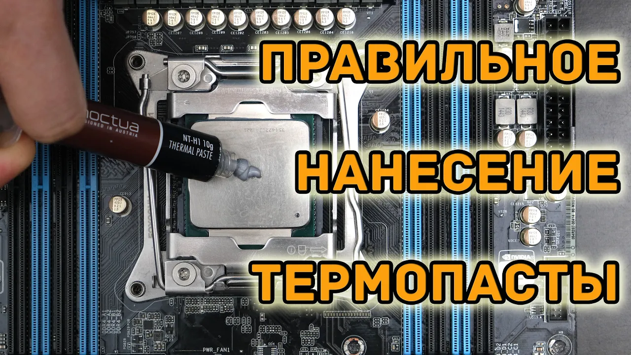







For standard desktop CPUs with integrated heat spreaders, the quantity of thermal paste applied does not significantly impact thermal performance as long as the entire IHS is adequately covered; the critical factor is ensuring complete coverage rather than worrying about whether you've applied too much or too little paste, as excess paste is simply squeezed out by cooler tension and doesn't harm cooling efficiency.
Thermal Paste Quantity: Benchmarking Application Methods on CPUs
Added:The function of the Integrated Heat Spreader (IHS) on modern CPUs and why it requires physical contact with a heatsink.
The basic physics of thermal conduction and how microscopic air gaps between metal surfaces act as thermal insulators.
The primary role of Thermal Interface Material (TIM) as a gap filler designed to displace air, rather than a highly conductive metal replacement.
How CPU temperatures are monitored, including concepts like core temperature, package temperature, and thermal throttling.
The impact of cooler mounting pressure and clamping force on thermal paste spread and overall heat transfer efficiency.
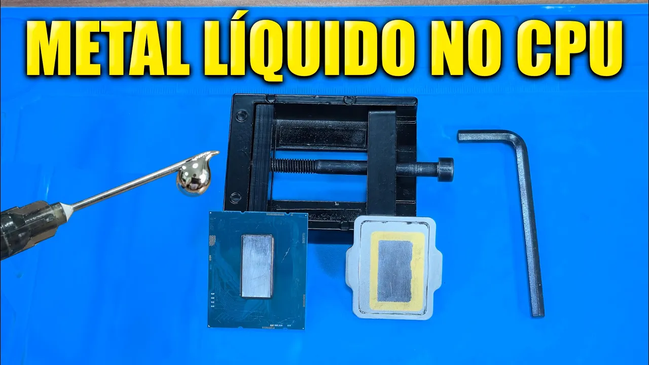
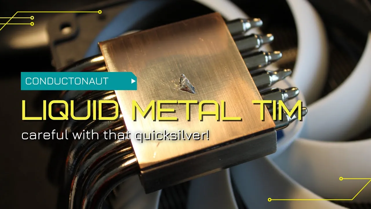
The properties, application methods, and risks of advanced Thermal Interface Materials, such as liquid metal, carbon pads, and phase-change materials.
The relationship between operating temperatures and modern CPU boost algorithms (e.g., AMD Precision Boost, Intel Thermal Velocity Boost).
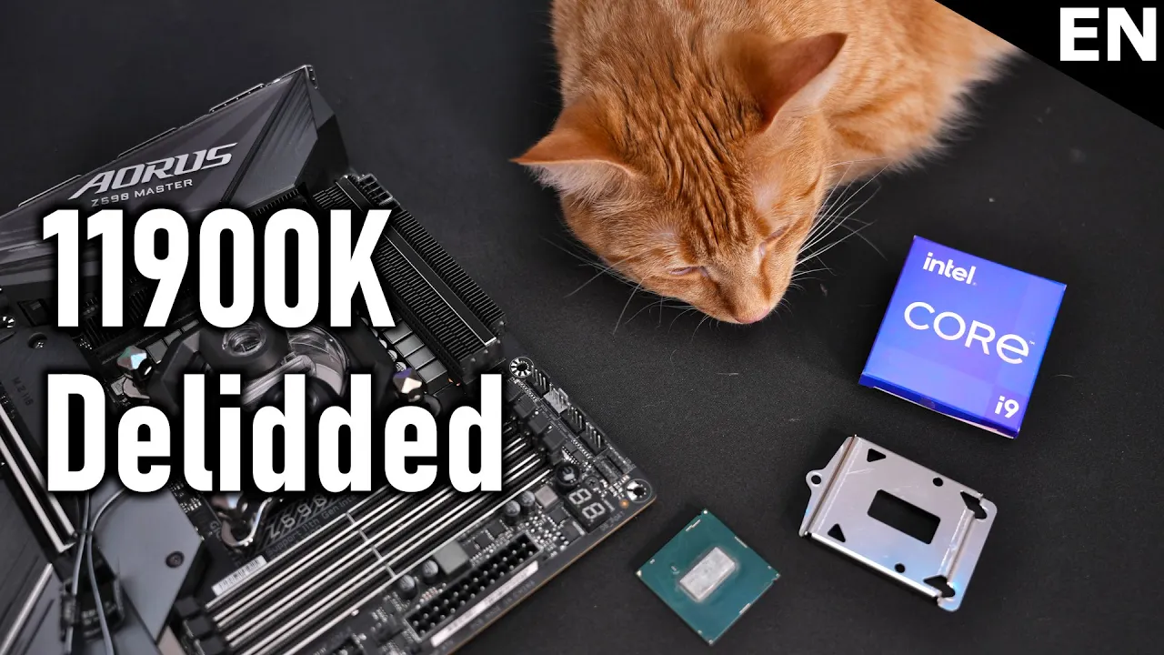
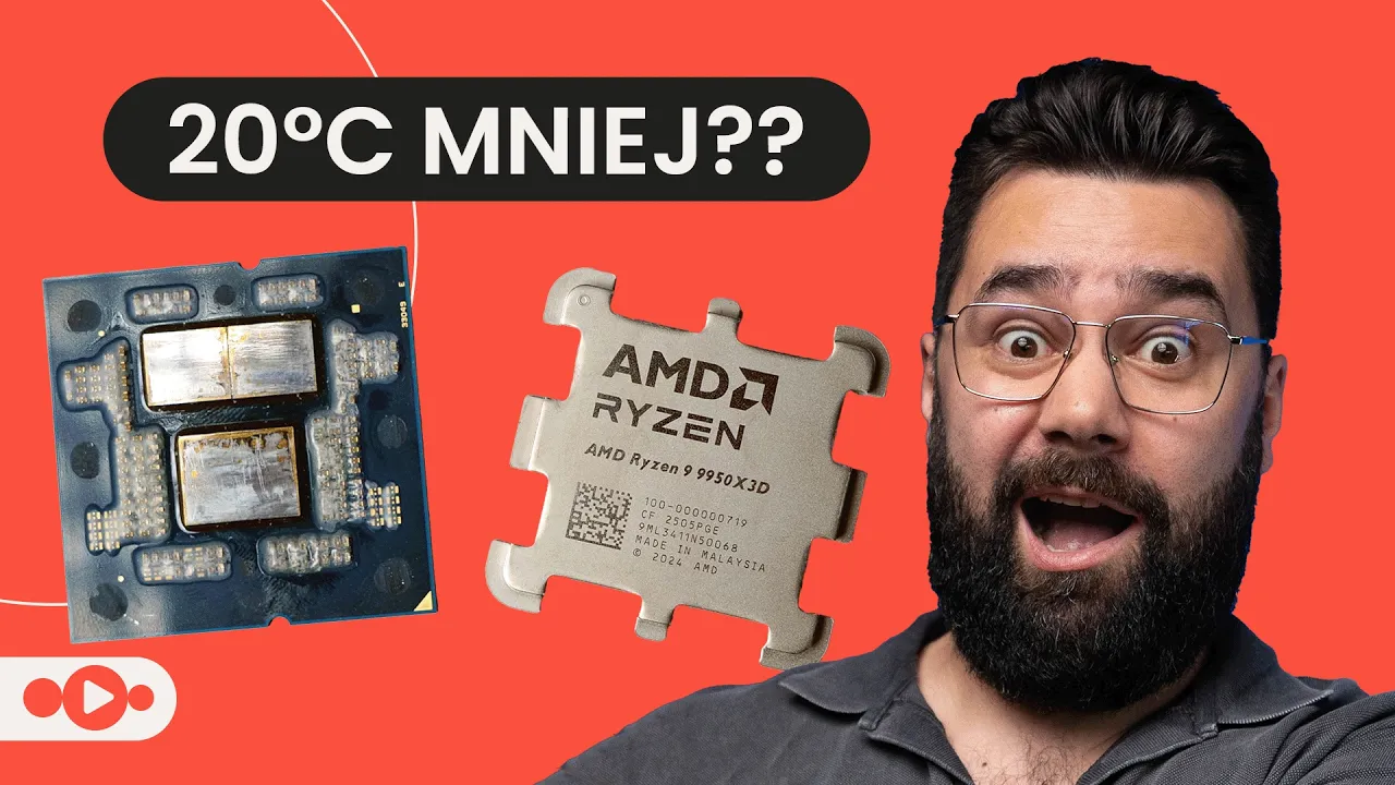
Advanced cooling techniques such as CPU 'delidding' (removing the IHS) for direct-die cooling applications.
3.3M views67.5Klikes20:57Original Release: 2018-07-27
Hey guys. So, you just caught me applying thermal paste to an 8086K. This is something we normally don't put on camera because it gets so much criticism, and I'm honestly not sure why. We don't put that much paste on there. It's not like it's an insane, completely absurd amount. It's always very reasonable, but people still comment on it being too much paste or too little paste. And it just seems like the kind of thing that no matter who you're talking about, which technical YouTuber, which user, there's always going to be comments about thermal paste. Hang on. I need to transfer over to my AMD socket and apply a good amount of paste to that socket as well. We're just building a couple systems today.
Hopefully, they work really well after all this thermal paste. Before that, this video is brought to you by EVGA's 19th anniversary giveaway. EVGA is giving away over $80,000 of components in its retro themed 19-year anniversary, including two signed GN modmats, and also several full systems, GPUs, motherboards, and more. To participate, click the link in the description below to start EBJ scavenger hunt, screenshot competition, or gaming events. Click the link below to learn more. Today, we are finally testing something that everyone on the internet loves to comment about, and that is thermal paste application.
So, we've tested this several times in the past. We tested it with Thread Ripper, tested it with even recently the H100i Pro Asetch paste versus manual paste. There are times that thermal paste application matters. There's a caveat there. and we'll get to that later, but it's basically it always just just cover the IHS. So, we're going to recap some of that stuff towards the end of this content. But today, what we're focus focusing on is an Intel size CPU.
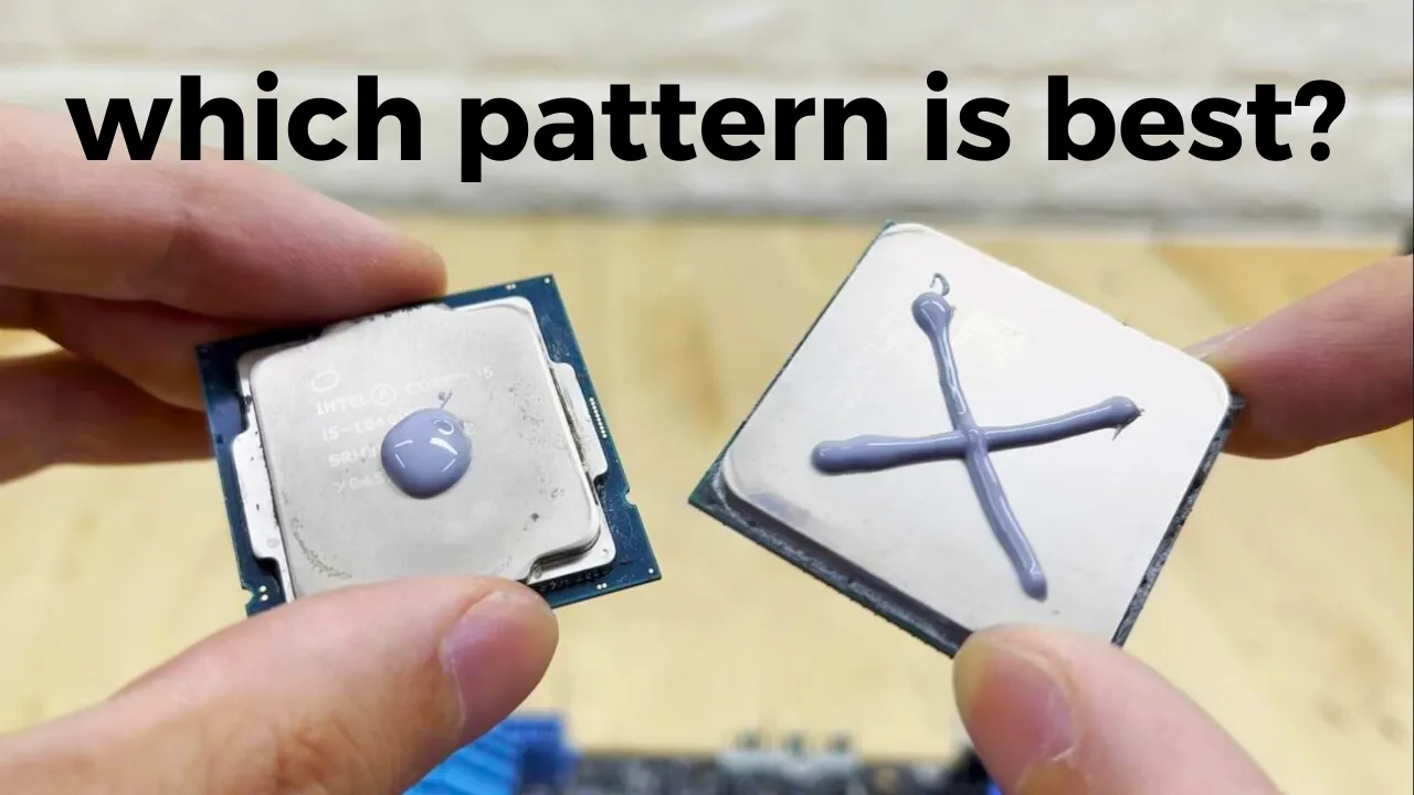
So, this will cover smaller desktop CPUs rather than HDT. And then we're also testing basically small blob like P size, which is kind of the common size that you hear people recommend to new builders. We'll test the uh larger blob that's kind of still within the realm of sanity for someone to do, but definitely too much. Uh and then we're going to do absolutely for sure too much thermal paste and also a manual thin spread across the IHS. So the thing here it's not about which method as in which pattern is the best. We've done that testing. It's basically irrelevant. But at the end of the day, all you have to do is make sure the whole IHS is covered for most of those high-end CPUs. So we're not testing like X versus a line versus a dot versus thin spread. That's not the goal. The goal is the quantity of thermal paste and nothing else. So, this topic came about again because a new system builder sent us a tweet a while ago and said, "Hey, I just built a new system and I posted a video on YouTube and people said I applied too much thermal paste. Do you think it's too much?" I looked at it and I said, "No, that's not too much." But it caused this question to arise, which is at what point is it too much thermal paste without going completely nuts and emptying an entire tube of this is actually some pretty expensive paste to empty out on it. the thermal grizzly cryonaut paste, but it was worth the gag. So, without emptying an entire tube, how much is too much? That's what we're testing today. Couple things to keep in mind. First of all, this has been done in the past. We tested Thread Ripper IHS uh sort of occupation of thermal paste versus the smaller area spread by an ASET cold plate. For example, we tested ASC plates versus fulls size cold plates, different tests.
We tested X99 CPUs recently with H100i Pro for a standard circular spread versus manual spread. We've done it, but now we're doing this on an Intel platform with a smaller CPU, which is kind of a standard for Ryzen as well with some differences in the MCM layout.
And we can finally look at the question, all the comments that everyone posts, the reason that we don't show thermal paste applications because it triggers stupid pointless comments and discussion and address it and see is there any validity to all of that. So, couple things to get through here first before we get into testing. Testing methodologies always will be fully defined in the article link in the description below. Patrick wrote the article. If you want to check out how we tested, what we did, check out that article. It will detail all the test components. It'll detail the paste used.
It'll detail the status of the CPU, the overclock, all that stuff. It's all down there. We're carefully controlling for the current. We have a current clamp on the 12vt rails. We make sure that the CPU is pulling the same amount of current for every test and thus the same amount of power in terms of wattage. And then we also keep the BIOS settings with manual voltage adjustment, manual core clock adjustment. Everything's manual, everything's fine-tuned manually on our 886K. So everything is very carefully controlled, including room temperature and ambient, which is logged second to second with a thermalouple reader. So that's the basics. Again, quick note that the test here is focusing very specifically on a standardsized desktop CPU. not talking about HDT today. And then finally, why paste? The reason we use thermal paste at all, and we have an old video on this from a TLDDR episode about how heat sinks work. The reason we have thermal paste is to fill the gaps, tiny microscopic imperfections often between the IHS and the cold plate of the cooler. And all that it needs to do is fill those gaps. Having more thermal paste is not better. It's actually worse because you have more of an interface to get through. So you want to have as little thermal paste as possible between those gaps to make sure there's not air pockets between the cold plate and the IHS because IHS is nickel plated copper.
Cold plates often copper. Those are two roughly 4005 watt per meter Kelvin surfaces or materials that should be conducting directly but they can't because of manufacturing tolerances. So instead they're tiny air pockets. Air is something like 0 out of three or 0.7 depending watts per meter Kelvin for thermal conductivity depending on the temperature of the air. And that's obviously not great compared to 400. So you put in a thin layer of thermal compound. That's why it's done. Let's get into the testing. Again, methodology defined below. And GPUs, by the way, completely sort of different idea, but I'll talk about that later. The first test was the big blob. The big blob test was the first one with usable results that we had. We had a couple ones with unusable results, which will be detailed in the article. We'll talk about why they were unusable. This is an excessive amount of thermal paste, but within the bounds of what a sane human might use.
The blob measured at 10.12x 12.22x 3.1 millimeters in size with the 3.1 being depth from a depth gauge. The cooler installed and tightened down only squeezed out a little paste over the edges of the IHS and there was a layer of paste that remained between the cold plate and the CPU. Naturally, conventional wisdom says that a really thick layer of paste is bad since ideally the cold plate and IHS should be as close to each other as physically possible, but we'll wait until the end of the content to compare temperature averages. Keep in mind that cooler tension forces the paste out of the sides when excessive and that removing the cooler will relieve that surface tension. To clarify, the after shots do not show what the paste looked like when it was hidden under the cold plate because we can't see that. The surface tension during cooler removal will sort of suck the paste back up and inward toward the middle of the cold plate. So, it's not 100% what it looked like, but you get the idea. Here's an overtime chart showing the data for the big blob test. We'll compare these results to the others at the end of the content. For now, we're bouncing between 58 and 61° C delta T over ambience, and we'll average the results later. Current is around 21 amps or about 250 to 256 watts at the 12vt rails. This next application is thin spread. This is the application method that we use for tests that specifically involve CPU thermal or cooler testing. That's because this is the most easily reproducible method and we can control our application for careful testing, especially when we're talking about multiple staff members doing the same test. This is also because we use the paste from tubs, not from tubes for most of our tests. And there's no better way to apply it. For many enthusiasts, this method, the manual application method, which often uses a spreader of some kind like this one, the manual thin spread application method is spoken in hushed tones and comes from ancient PC building tradition where divor and whirling dermishes ever clairvoyant and how the paste will spread once you apply the cooler to the socket, have long foretold that this application is the best. And so we decided to test it. So knowing that the paste whisperers out there and the soothsayers of thermal paste deem that this is the most critical aspect of any PC build ever on the face of the planet thermal paste application. It seems suitable to look into it and see does it actually produce a difference versus just doing a dot in the middle that's reasonably sized. And so as the mystics have foretold that spreading a thin layer ensures maximum contact between the cold plate and the IHS and thinning it out makes the gap between the two as small as possible. We can look into whether or not that helps. In this instance, our application can be seen in the photos both before and after. But again, note that the flash on the camera makes the application appear a bit thicker than reality. Don't worry, it was pretty damn thin. You could almost see the IHS under it. One worry with this method is that the uneven surface could trap air bubbles when the cold plate is pressed against it. But there's no indication that this was a problem in any of our testing, and we did multiple test passes. Here's our overtime chart of performance. It's worth mentioning that regardless of thermal performance, a thin layer of thermal paste is really easy to deal with. There's less danger of uneven coverage. It uses a minimal amount of paste, and it's easy to clean up. There's also the peace of mind that comes from knowing with 100% certainty that the IHS is fully covered without ever taking the cooler off. Next is the P-sized DOT method. This is the method we use for tests where CPU temperatures aren't vital, like building a new Windows OS or just testing to see if all the components work. It's extremely fast and repeatable. That may not matter much to the average user, but we swap out multiple CPUs and coolers a day, and convenience really matters. The first photo showed the dot, but the after photo reveals one of the downsides of doing just a blob of paste that's kind of on the smaller side, which is that extra care is needed to put even pressure on the cooler when tightening it down. The hot spot over the die was covered, but one corner of the IHS was left dry. That's something we avoid in normal testing, but in this test, it's an important variable that we want to account for. This is a potentially real user result, and so we tested under these conditions. Our overtime chart thus far reveals mostly similar results, but we'll have to look at the average results at the end of the test for a more conclusive analysis. As a note, the P-size dot was 9.16 mm x 8.76 x 2.97 deep. This last method is one that we simply dubbed too much. It's 50% of the comments on YouTube about thermal paste with the other 50% being too little. In this instance, we really did apply way too much. Objectively, just to make absolutely sure that there's no question this is a wasteful amount of paste, even regardless of performance, even in a scenario where performance is the same, this is clearly just plain wasteful and annoying to clean up, especially if you're using high-end compound.
Dimensions are immeasurable here, but basically the entire IHS with a 1.76 millimeter height at the peak using a depth gauge is what we ended up with.
Here's our overtime plot. This is just too much paste. Again, the cryonaut paste we used isn't conductive, but some are. And even when they aren't, it's still no fun to clean the gunk out of a CPU socket. Even still, in the overtime plot, we're really not seeing bad performance. It's pretty comparable to the previous test that we've done. as seen in the picture, not only did the paste ooze out all over the edges of the CPU, it also dripped out over the socket cover and the motherboard when the cooler was removed. So, probably don't do this, but in terms of thermals, as you've seen thus far, it doesn't look terrible. We'll get into more of that in a moment. Now that we've looked at each test individually, the before and after photos, ensure that the current provision was the same for all of them, clocks are the same, all that stuff.
Ensure that we tighten the screws on the cooler in the same exact fashion and pattern for every test. Lots of controls here for testing. Now that we've done all of that, we can look at the average core temperature at steady state rather than these individual overtime charts.
It's a bit easier to read. And this will include the current for each test, which will help illustrate the power consumption being the same for each test. As always, note that current times voltage gives you power. So, we're trying to get watts. Current times voltage. Our voltage is 12 volts down the 12volt rail for EPS 12volt cables.
And that puts our power on average at around 256 watts or thereabouts assuming a 21 to 21 point something amperage for the current. All data lands within margin of error here looking at our steady state or equilibrium chart and well within margin of error at that point because our top tobottom range of results equates 0.77° C of difference. That's between the so-called P-sized dot and the second pass of our thin paste spread. Our error permits for this difference. There's not enough statistically significant difference here to establish a real performance delta between the results.
All results land at about 58 degrees delta t over ambience, plus or minus 0.46° C from the median. Average current as clamped at the 12volt rails was 21.5 amps with only marginal differences within variants. Test conditions remained the same. Room ambient and HVAC were controlled and monitored each second. and the liquid cooler was permitted to reduce water temperature between tests down to steady state idle in between each test pass. We feel confident in our data on the CPU.
Remember, this is a 256 watt load with a delted CPU using liquid metal. More of the methodology below. So, this is one of the most likely scenarios where you would see a difference in the quantity of payest impacting results. It's a lot of heat, a lot of power, and it's a fairly high overclock. So because of this, the conditions of the thermal interfaces are stressed, thus creating an environment that would yield differences should any exist. It just doesn't seem like they do. This last graph is a mess, but that's intentional.
So, let's walk through it. This graph includes the temperature logs for each of the valid tests, but zoomed in to a range of 8°. We know the scale is insane, but that's kind of the point.
Almost every data point within the test period falls within a twoderee range and that range is 58 to 60° Celsius delta t over ambient. The reason the graph is hard to read even at this scale is that the temperatures are all almost exactly the same. Our testing here agrees with many of the tests that have been done in the past both by us and by other media outlets. It's we've seen this before in our own content ages ago. Luke, anyone remember Luke tech tips and that period of Linus Tech Tips where Luke was on camera a lot of the time. Well, Luke did a video on this as well and saw pretty much the same thing. So, we're not the first people to see this. We've instituted a ton of controls here just to make sure it wasn't variance because thermal testing is hard to do, right?
There's there is a lot of variance genuinely with a computer. So, we've done a lot to control that and we're just we're not seeing a difference on this platform under these test conditions. Things to keep in mind, different type of paste. Maybe if we use some garbage paste that's super low thermal conductivity, maybe has some curing issues or something like that, you might start to see differences in data arise. How relevant they are, it's hard to say, but when we're pushing for higherend or even more realistic user scenarios, doesn't look like a lot of difference on this platform. There are differences on things like Thread Ripper, on X99, X299, HDT platforms, things that have a large IHS, and we'll go through some of those in a moment.
But just remember here, putting a moderately sized blob in the middle of the IHS is pretty safe for the most part asterisk. See the HGD section in a moment, but for the most part, that's fine. Same with the P-size test. It's just the only thing to worry about is if you're covering the whole IHS or not.
And as long as you do that, you're fine.
Things to be careful of, of course, would include if you're using a conductive thermal paste. Some of these back here are a couple of them are conductive. So, you're using anything like a diamond compound or a silver compound or anything that has conductive properties because it's got metals in it. That would be a concern of using too much because you use too much and it spills over the socket and gets onto the board, you might short an SMD or something like that. But that's you would have to basically empty a tube to cause that to happen. So, uh should be something you don't really have to worry about actively. So, putting too much paste on the socket won't generally hurt thermal performance because tightening the cooler down squeezes out all the excess. That's why it's okay to put so much on there. Even in our too much test, the socket tension deals with most of it. Too little paste is bad, but anything above the minimum threshold should be more or less fine. And once the cooler is tightened down, it pretty much equalizes everything anyway. So, the problem with excess isn't thermals.
It's just danger of shorting components, being wasteful, blowing through an entire tube of thermal grizzly cryonaut, things like that. Uh, and they are an active advertiser of ours. Not on this video, but if you want some, we'll link it below. Anyway, so let's recap some of our older coverage just to illustrate that this can be highly situational despite our results being relatively conclusive for the Intel desktop part here today. As a recap, we previously conducted similar testing for the AMD Thread Ripper CPUs published one year ago. The testing conclusively demonstrated that the biggest consideration, particularly with multi-chip modules like Thread Ripper, is that all dyes need to be covered. You can see in our TR4 paste application thermal chart that full IHS coverage also helps. something we demonstrated again in our knock to a full coverage plate Thread Ripper benchmarks and we illustrated this yet again in our Enmax CLC benchmarks where the small ACE detect cooler cold plates struggled to keep up. The difference with Thread Ripper again is that we're working with a multi-chip module and a massive CPU package. This is the opposite of a small KQU Intel CPU and although similar and multi-d approach to Ryzen, the desktop AMD CPUs are significantly smaller.
Finally, our most recent testing of this kind involved the Asetch made Corsair H100i Pro, where we demonstrated that manual application improved cooling performance in a meaningful way. We spread paste out over the entire heat spreader of an X99 CPU as opposed to using the stock ASX circular application that covered only the central portion of the IHS. And there's one key difference here from the other stuff. The testing involved an X99 CPU. It was actually producing less heat than our 8086K that we tested with today, but the significantly larger IHS meant that there was more to be gained from covering the rest of it. The ASC circle neglected about 25% of the heat spreader surface area and the H100i Pro cold plate is a bit smaller than previous ASC designs, which also mattered because this is again a larger chip. So, different test conditions apply. The 8086K application methods never left more than 10 to maybe 15% of the spreader uncovered. And that was in the P-sized dot where we had one corner slightly uncovered. So that's the main difference between the thermals. Quick recap then. Just make sure the IHS is covered. You're fine. Anyone who's in the comment sections complain about people applying too much thermal paste or too little thermal paste probably just shut up and stop because it actually almost never matters. There are instances where it matters. A good example of sometimes when you should be more careful about having maybe too much instead of too little would be a GPU.
There's no heat spreader on a GPU. It's just an exposed die. It's direct contact. So, this is a great example where if you apply too little and you have a corner of it just slightly uncovered and some of the dye is not getting coolant, it's got a hot spot in there. The problem is those cores can burn out and it's happened and it's really not that difficult to make it happen. So GPU is an instance where we would lean towards too much rather than too little because if you do anything above again the minimum threshold for the amount of paste to cover the whole die assuming you're not doing manual spreading. Anything above minimum threshold should be fine as long as you're not going just completely unreasonably crazy with how much paste you're applying. Same goes for the most part for the desktop CPUs except there's a bit more tolerance for having too little because there's an IHS there to spread the heat out. And as long as you cover the central dye area where the dye is actually located under the cold plate, you can get most of the heat out of there, it'll be fine. And then there's obviously some kind of compound between the die and the IHS anyway. So you don't have to worry about a hot spot forming between the die and the IHS where the die is most susceptible to damage like a GPU. So they're bit different but also similar in some other ways. So yeah, just make sure you cover the whole thing and uh beyond that, it's really not worth worrying about. So, thank you for watching. It was fun looking at the old Luke Tech Tips video from years ago on this topic. And hopefully we did it justice by going a bit deeper on it as well as time has now permitted more things to come out like Thread Ripper, which didn't exist then, and that obviously is a bit of a different scenario. That's all for this one. Subscribe for more. As always, go to store.gamersex.net to support us directly. You can buy our new beer glass we just got in actually. It's got a gold trim on it and the GN tearown logo on a cobalt colored glass. or pick up one of our video card tearown posters and go to patreon.com/gamers nexus to join our Discord. I'll see you all next time.
[Music]
Up Next

45:34
How Singapore Is Building Coastal Defenses Against Rising Seas
@sgPUB
21.1K views•2022-10-26

30:32
Ultrasonic Transducers: Resonant Frequency Measurement and Horn Design
@imajeenyus42
229.9K views•2017-02-22

26:05
Noctua NH-P1 Passive CPU Cooler Review: Benchmarks & Schlieren Imaging
@GamersNexus
401.7K views•2021-06-29

33:39
How a Student's Question Saved a NYC Skyscraper from Collapse
@veritasium
22.8M views•2025-04-26
Related Study Plans & Knowledge Roadmaps
Structured learning paths in Engineering
engineering
Building Acoustic Levitators: Physics & Arduino
01The Physics of Sound and Standing Waves
02Piezoelectric Transducers and H-Bridge Drivers
03Arduino Programming: Generating 40 kHz Signals
+ 2 more learning modules
14h5 modules
Explore Roadmap
engineering
Building Peltier Cloud Chambers: Particle Tracks
01Cosmic Rays & Cloud Chamber Physics
02Thermoelectric Cooling (TEC) Fundamentals
03Custom Liquid-Cooling Loop Design
+ 2 more learning modules
18h5 modules
Explore Roadmap
engineering
Yagi-Uda Antennas: Modeling, Build & VNA Test
01Introduction to RF and Antenna Fundamentals
02Yagi-Uda Antenna Design Principles
03Antenna Modeling and Simulation in 4NEC2
+ 2 more learning modules
18h5 modules
Explore Roadmap
engineering
ECG Monitor Design: Op-Amps, Filters & Noise
01Electronics & Breadboard Basics
02Op-Amps and Instrumentation Amplifiers
03Bioelectricity and ECG Fundamentals
+ 2 more learning modules
18h5 modules
Explore Roadmap