





![Unit 5 - A ] Turbo Machines Centrifugal Pumps Intro](https://i.ytimg.com/vi/aHqNW-i86Kc/hqdefault.jpg?v=5f916469)




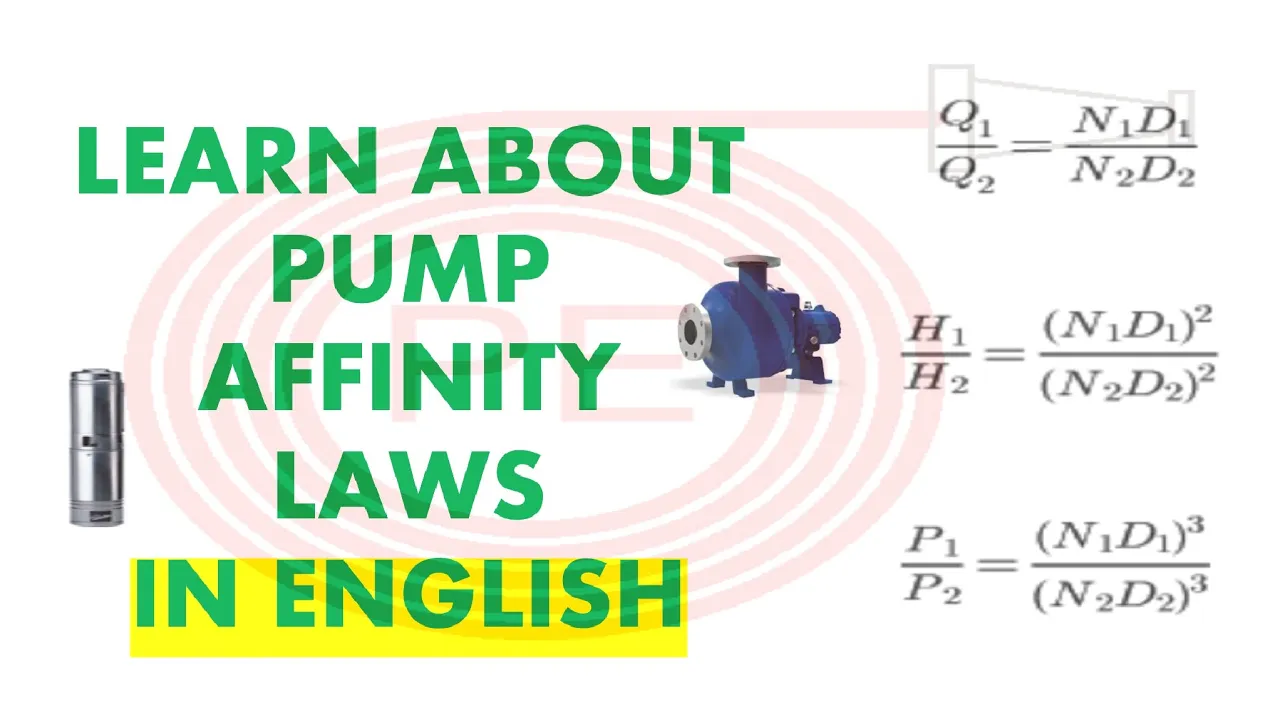











A pump curve illustrates the relationship between flow rate and head pressure for a centrifugal pump, while a system curve represents the total resistance of the piping network at various flow rates; the intersection of these two curves determines the actual operating point of the pump in the system, and optimal pump selection requires positioning the Best Efficiency Point (BEP) within the 85-125% range to maximize efficiency and minimize wear, with variable speed drives utilizing the Affinity Laws (flow proportional to speed, head proportional to speed squared, power proportional to speed cubed) to adjust pump operation dynamically based on system demand.
Pump Curves & System Curves Explained | HVAC Engineering Tutorial
Added:Fundamentals of fluid dynamics, including flow rate (Q), pressure, velocity, and the concept of 'head' (H).
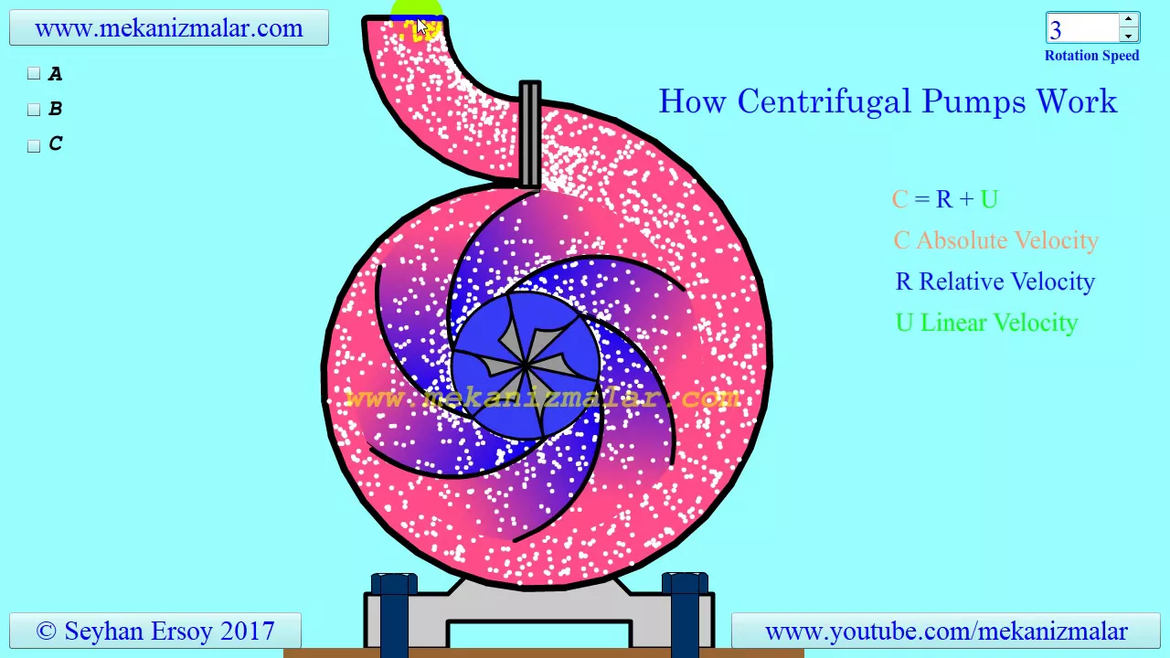
Basic working principles of centrifugal pumps, specifically how rotation converts mechanical energy into kinetic and pressure energy.
The physical difference between static head (elevation/pressure lift) and dynamic head (friction and minor losses) in a piping network.
Familiarity with the pump affinity laws, which govern how rotational speed affects flow, head, and power consumption.
Analyzing multiple pump configurations, specifically how to construct and read combined curves for pumps running in series or parallel.
The study of pump cavitation, including calculating Net Positive Suction Head (NPSH) margin to prevent damage and efficiency loss.
Advanced energy-saving control strategies using Variable Frequency Drives (VFDs) to match the pump curve to dynamic system demand.
Hydronic system balancing methodologies, such as using triple-duty valves, circuit setters, and pressure-independent control valves (PICVs).
16.2K views345likes1:03:42Original Release: 2023-01-17
all right Tony first with Armstrong fluid Technologies here to discuss pump curves and system analysis take it away Tony first thank you thank you Mr mormino I appreciate it good morning everyone hope everyone's having a wonderful day on this uh middle of December Thursday as we get ready for the uh the upcoming holiday season uh and so hopefully today we'll get to educate everybody a little bit about pumps and pump curves and what all that information on pump curve really means and and then once you have all that information what do you do with it when you're standing in the mechanical room look at the pump how do you do something with it so that it makes sense so at the end of this today my goal is so that everybody understands the component parts of a pump curve so to understand what a system curve is what you understand what a control curve is and what the difference between a system curve and a control curve is and then as well how to use a pump curve to validate flow and performance now when I look at my parent wants to misbehave as we look at pumps and pump systems we've got to understand some real simple Basics and the whole team between the engineer purchasing maintenance contractor you know everybody has to be involved in this scenario okay you know Engineers are concerned how it works quite simply that's what it really comes down to contractors they're concerned how do I get the system installed and running building operators how do they keep it running along with that is the maintenance costs what do I have to do to maintain it and of course purchasing we all know how wonderful that is they're all worried about first costs and each one of these groups has a stake in the process each one of them also thinks theirs is the best rationale and when you look at it and you understand what we're doing with pumping you have to look at all these different stakeholders and look at the total system and figure out what really makes the best sense in upfront costs life cycle costs everything else to understand the whole system okay now when we look at pump systems one thing that we've found over the years is we have found that most pump systems are oversized this is not a bad thing and it's nothing against any of you that are Consulting Engineers there's nothing wrong with it but what happens is what we found is that one we all put safety factor in I was a design engineer before I came to work for Armstrong and we all have safety factors that we apply to our designs because we can't control the construction exactly so that leads to some oversizing that's the first thing second thing is we have to understand that we got to look Beyond Energy savings okay we got to look at the entire system and one of the things when we look at energy cost we can't look at it just at that first year energy cost we've got to look at it over the lifetime of the building we really have to make sure we understand life cycle costing and what that really means and so this is why understanding pump curves and understanding how to interpret the data from a pump curve is really really critical to being able to go out and figure out where your system is really running and determine how far oversized your pumps may be now it's getting better as we've moved into the era of computerized design and doing piping piping system evaluations via computer instead of doing them the way I learned how to do it with a Green Sheet spreadsheet and pencil and a slide rule um yes I am that old um things have changed a lot so it's gotten better but if you go in and you do a lot of retrofit work understand that there's probably opportunity to downsize pumps in an existing building to get them to more closely match the System Dynamics for flow and head and that's important for efficiency too correct oh exactly um so if you oversize the pump you could be safer if you're going to talk about that okay I want students so what's the like in the industry today how would you rate the average um designer's ability to read pump curves is it something that has gone to the Wayside or something that's always been a challenge or what do you what are your thoughts on that overall Tony what I'm seeing is that most Engineers kind of sort of understand pump curves they understand some of the information that's being presented but when we move into variable speed pump curves and optimize pump selections um a lot of Engineers and contractors and tab contractors don't understand they really got to pay attention to the data that's on the curve because I've had a couple of I've had a couple jobs here recently where they've come back and said oh no you guys have put you built the pumps wrong they have the wrong impellers in them you know tested and I'm looking at what they tested and they tested at different speeds than what the pump was designed for and I'm going guys you tested it at the wrong speed reduce your speed to here which is what the maximum speed for this pump was and retest your your shut off head and they come back and go oh wow you were right we just we were wrong and I go okay and I've had Engineers call me and go well how do I know what the flow is I've got a pump curve but I don't know how to get this information so hopefully today we're going to kind of talk about that a little bit and get everybody to understand what do you do when you're standing in the mechanical room right um so hopefully this will Enlighten people a little bit um right and and make everybody's job a little bit easier um what I'm finding um from an engineering level um it's about 50 50.
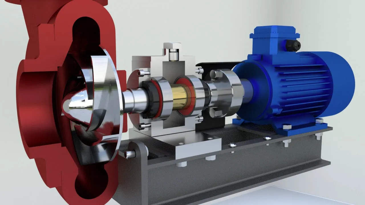
um on Engineers that really understand pump curves and Engineers that don't really understand pump curves at a deep dive level um so hopefully we can Enlighten a whole lot of people today so before we start talking about pump curves let's kind of talk about what a pump is okay and and what the parts of it are okay in really simple terms you've got an impeller or impellers because we make multi-stage pumps and those are just impellers that are in series with one another which is no different than building pumps in series with each other we have a Volute which is the the big round part of the pump we have the casing the body the housing there's maybe a diffuser in it there may be a bearing assembly depending on whether it's vertical inline or horizontal end suction pump then we have a driver okay now we're not going to talk about whether it's constant speed or variable speed and whether you have a starter or variable variable speed drive on it because that doesn't affect the pump Construction in and of itself all pumps all have the same basic component parts and so you got to understand those parts that are in there and understand those parts are fixed by us as pump manufacturers we decide what size the casing has to be what size the impeller has to be to optimize motor horsepower to flow and head that you as the engineer need for your system okay so if we look at pumps how do we determine flow well that's what Engineers are going to do they're going to tell us what flow they need in the system so if it's a booster system for a domestic water system it's based on fixture count so how many Plumbing fixtures are out in the building how many water supply fixtures are out there you turn it into water supply fixture units and you can use Hunter's curve or iatmos water demand calculator or any number of other sizing tools out there and tells you how many gallons per minute you have to have for chillers and boilers we're either looking at tonnage or we're looking at um you know design delta T given the heating heating output of a boiler um you know so it's also based you know it's on that BTU load calculation um and if we're looking at drainage coming off a roof or you know designing a sump pump it's all based on square footage so that's how we determine flow that tells us different flows that we need for different systems so what do we do about head loss okay well when I look at head loss head loss is always static requirements plus the head loss of moving water through the piping system okay now the static requirement is only a critical component if we're talking about an open system if we're talking about closed loop system the water that goes up also comes down and those two numbers offset each other however if you have an open system where you have an open cooling tower then we have to worry about static head and we have to worry about static head on both sides of the pump for suction head and discharge hit and those two are additive in that case so understand depends on whether it's an open system or closed system as to whether we're dealing with static or not um velocity head really has a very very small impact on total head in most HVAC applications now I'm not telling you that it doesn't but in most HVAC applications it is minimal okay so when we look at a test rig and what you're seeing here the pictures that I've got up on the screen are a hi test rig setup okay so we build pumps to the Hydraulics Institute standards we have to just like every other pump manufacturer and um when we look at this this is how we set up and this is the way we test okay understand that when I'm doing my test setups I want to be two pipe diameters away from the pump on the suction and discharge side so one of the problems that we run into is test and balance contractors or somebody out there trying to read what the pump is doing they usually put the gauges in the gauge tappings that we've installed in the casting of the pump don't do that if you look at the pump and you look at the velocity through that pump the velocity is extremely high on the suction side and on the discharge side of the pump part of the design of the pump if you read the pressures at those points you have to account for um velocity and velocity pressure okay so in the velocity head that's imparted to it so what we recommend is and from a design perspective what I'd really like everybody to be able to do is design their systems to put Peach plugs two pipe diameters Downstream of the suction of discharge flanges of the pump so we get really nice neat clean flow we don't have a velocity head impact on our readings and we get really good measurement data okay so understand that if we have a big huge change in elevation from where these readings are at so if you're taking readings up near the ceiling and down near the floor elevation may play into it if the pump's not running okay so understand that pressure is nothing more more than Force per unit area and it's in the U.S here it's measured in PSI so Loop pressure is the pressure exerted by the weight of air above it at any point in the Earth's surface okay for most places it's 14.7 psia at sea level if you are designing a open system keep this in mind gotta pay attention to elevation above sea level I had a job earlier this year the the job is 2000 just a little over 2 000 feet above sea level the engineer did all his head loss calculations for the cooling tower and did it based on sea level well guess what at two thousand feet above sea level atmospheric pressure is not 14.7 psia it's about 12.9 don't hold me to that number I'm doing it for memory and in my age there's a lot of stuff right on around in my head um so understand that you got to pay attention to sea level and where you're at in relationship to sea level you know Tony you're in the mountains in North Carolina which what's your elevation above sea level there do you know about 2500 feet okay so if you're designing up in the mountains where Tony's at you know you gotta readjust your atmospheric pressure to be 2500 feet above sea level okay God pay attention to that because it will come back and bite you that's a hard one to fix too uh yes it is it is not pleasant to fix and I really hate to be the guy to tell you that um as you know when I when I talk to Engineers because a lot of a lot of my job I spend out working with Engineers helping to figure out why their system isn't doing what they thought it was doing yes adding more pumping power is not easy no no and it's like adding more cooling it's just not that easy no and it gets worse when we have to start changing motor sizes and we bump from you know 40 to 50 horsepower motors and we have to start having to change the drives it gets ugly so um I'd like to avoid that at all costs um because it's just not fun yeah so if we understand you know one of the basic component parts of a pump curve is understanding the different numbers that are on the Curve so if I look at the left hand side of the curve over here that is my head losses okay that's my system head and across the bottom is flow rate now this particular one it's in gallons per minute this could easily this may say down here times 100 times 1000 times ten thousand um so we we keep the numbers small and you just have to figure out whether you're in the tens hundreds thousands whatever okay then we have you know our system curve which is that line that parabolic line right there okay and so that's what we're doing and we we derive a system curve a system curve is derived it's a mathematical calculation because we know that as our flow goes up or down the system head loss moves up and down from zero flow where we have zero head all the way up to maximum flow where we achieve maximum head and head moves up and down by either the square or square root depending on whether we're going up or down okay this is all related to the Affinity laws so if I look at pump curves and I look at pump Curves in their individual component parts that we see when we're looking at a pump curve in in anybody's hit the button there um curve data okay so the first curve that we have here okay what we have here is that is just a standard pump curve okay so we go from over here and this is known as shut off head on this side and this is known as run out okay once you get out in this last 10 15 percent of the pump curve you really don't want to run there okay you start to get into the unstable region of the curve and yes we show it out that far we really don't want to be running out just because the pump's just spinning so fast because the lack of pressure it's yeah the pump is trying to move a whole bunch of water and the velocities are real high and um it's no different than a fan curve you know when you get to the end of the Curve strange things start to happen right right and so keep in mind fan curves and pump curves we're moving a fluid okay it's just with pump curves if the fluid gets out of the pipe you get wet in a fan system if the fluid gets out of the ductwork you just get blown on right right okay so the next curve we look at is our system curve okay so that is just a mathematical calculation from zero flow zero head okay and normally it starts down here at the bottom but zero flow zero head all the way out to the end okay it's just a mathematical calculation every one of us that builds pumps we will pot the system curve for you because you tell us what your design flow and design head is and we can do math from there those are determined by the test stand setup you went over earlier the oil pipe diameters yeah the design and ideal under ideal conditions right the design flow and design head comes from the design engineer and then all the curve data comes from us putting it up on a test stand and knowing what that blue pump curve is actually going to look like so when you see a pump curve when it comes out to you as an engineer what you're getting is the intersection of the two where the system curve and the pump curve intersect that is your operating Point that's the duty point that you've selected or you've said hey Mr Armstrong I want a pump that'll do 5000 GPM at 100 feet ahead and that's where that Dot's going to be okay so that's what that is so next thing we got to look at and this is where pump curves start to get a lot more complex okay because we put a whole lot more lines on the pump curve yeah okay the first thing that we're going to look at is we may have multiple impeller sizes shown on the curve because we build pumps with a lot of different impeller sizes it may be the exact same pump same casing same motor same motor speed I should say um because the horsepower is going to change a little bit as we move up and down on impeller size and flow and head um so we may show this is what's called a family curve okay and in a family curve what it means is we're going to show all the available impeller trims that we build for that particular casing size okay so that's why it's a family curve but nothing's changed any there's total head okay we have it in both feet and meters because we got to serve both markets okay so there's our headline there's our impeller diameters we have another one on here called npshr which is in that positive suction head required and sometimes npshr numbers show up here at the top sometimes they're down here at the bottom most of our curves they're down here at the bottom and there's a chart they'll tell you what that scaling is then the next thing you see is these isobaric lines on the curve those are the efficiency lines okay so as you move back and forth across the curve with different impeller sizes you notice your efficiency is moving around okay and that's how efficient we're using the motor power and how much of that we're using effectively and efficiently okay and then this last line here this green line that is our motor horsepower line so you see we start down here at 200 horsepower is the smallest one way down here and it goes up to 50 300 350 on up to a 500 horsepower pump now some things to pay attention to okay everything we show is done based on a specific gravity of one so if you got glycol in there it's a whole different ballgame when you actually do your pump selections okay family curves are always based on water because that's what we have to do we have to establish a benchmark and it's 65 degrees and plain water when we move into an actual selection and you tell us in the selection what fluid type you're running whether it's ethylene glycol propylene glycol calcium chloride some other form of brine you have to tell us all that you also have to tell us the operating temperature if you don't tell us the operating temperature we're going to assume 65 degrees well as we all know if I have ethylene glycol or propylene glycol in the system as I start to drop the temperature specific gravity in my density change okay which will affect horsepower so understand normal chilled water system if I'm operating at 45 degrees or 42 degrees ethylene glycolor propylene glycol temperature really doesn't bother the horsepower significantly not enough that you're ever going to notice the difference however been working on a job with a large customer they are running 15 to 20 degree propylene glycol in the system that makes a huge difference on specific gravity and density so it changed what we had to do from a pumping standpoint it bumped our horsepowers up a little bit um we also have the same issue um one of the things we're seeing in the data center world is starting to see more and more um single phase and two-phase immersion cooling systems okay where the servers are actually sitting in a tank of liquid that liquid is a dielectric heat transfer foot yes we can pump it it's not a big deal um we have made do some different things depending on the fluid we have change pump SEALS or something like that but we can Pump It understand that stuff is basically an oil okay it's kind of a mineral oil based kind of product so as we do those specific gravity and density plays into that as well so if you get one of those applications reach out to the guys at Insight partners and they'll work with you they'll work with us and we'll get the right pump selection for you sometimes we have to bump horsepowers to make it right okay so Tony I got a question here if you want to sure go for it take a quick question um and for those watching please ask questions gives Tony a chance to get a glass of water and rest a little bit so we always appreciate that um Paul Holloway asks those efficiency curves are only mechanical efficiency correct question mark as opposed to water to wire efficiency this is um a combination of mechanical and hydraulic efficiency which is what we're required to publish based on hi what is what is meant by water to wire did that actual job site no wire to water efficiency is what we're looking at which is all about motor horsepower and how efficiently we're using the motor horsepower okay so you know we have a we have a certain you know if you look at a pump curve or a fan curve um we may require a 450 horsepower motor but the absorb the absorbed power may only be 400 horsepower okay that's brake horsepower so what we show is is that combination of the two for hydraulic efficiency and absorb power efficiency um because that's how we have to rate pumps based on hi and doe and everybody else gotcha I've not heard that term before and thank you Paul Paul Holloway maybe I've heard it but I haven't heard it in a while I'm not sure you've spent too much time on the air side young man yeah pumps are new to me as far as a rep as in the last couple years so yeah okay thank you Paul if you look at a typical pump curve one of the things we see today is variable speed pump curves okay now you notice it kind of looks like a regular pump curve okay we got flow we got head we got a system curve here so that's the system curve I was telling you about that we plot for you okay and that's your design Point there's your motor horsepower line so I've stripped a whole bunch of stuff out of this in this particular application this is a variable speed curve okay so this is not these are not impeller sizes because in a variable speed application you know I can't change the impeller out I can but every time you wanted a change the flow in the system you don't want to change the M power out so we put variable speed drives on to be able to move the pump back and forth and change the flow rates so what's going to happen is these are our speeds so this is 100 speed uh 80 60 50 40 on down to minimum speed now you notice there's another line on here called the average load of the qpc curve that's that orange line that's known as the quadratic pump curve what that actually is if we look at a system and we know what the system curve is we know what the design point is and when Engineers as you Design Systems you say you know you'll tell the building automation guy is going to put a differential pressure transmitter out in the system and control to a set point right well we know that if we look at it at the pump the the calculated value of what that should be is about 40 percent of the design head so that's what we start down here that's 40 percent of what the design head of the system is and we start there and we move upward and that's what we call the control curve and if you use an Armstrong pump with sensorless control where we don't need to sensor out in the building automation system we use the Affinity laws and speed power and flow to determine where that pump is running at any point in its curve um we base it on a 40 minimum okay and and we calculate out that quadratic pump curve and that's how we control and that's what's going to control the speed of the pump based on system differential parameters as valves open and close and change the head losses in the system okay gotcha so the next thing we have to look at is what's known as the best efficiency point of a pump now if I look at the requirements of ashrae and ashrae says that I really want to operate my pump between 85 and 125 percent of the best efficiency point I'll show you a slide a minute as to what that number really means so if I look at my pump curves okay here's my pump curve there's my operating Point there's my efficiency curve okay and I'm running at 85 percent of best efficiency that's an ideal spot to be okay and understanding that you're going to maximize the life expectancy of the pump and minimize pumping system problems as long as you're in that 85 to 125 percent of best efficiency range okay so if I look at this curve and this is really what we're putting out there every pump has an allowable operating range okay and that is the the range at which that pump can operate over its operating curve but understand that there's also the preferred operating range and as long as I operate within that preferred operating range I'm going to avoid all the bad things that can happen to pumps like cavitation damage I avoid suction and discharge recirculation because there's no physical seal on the impeller inside that casing so the discharge water can actually move through the casing and go back in on the suction side um and I get suction research I get discharge recirculation um if I have excess wear at the impeller eye I can get suction recirculation there um all those things can happen if I'm operating further and further away from best efficiency point um we also start to change thrust loads we start to affect bearing and seal life and we get higher temperature rises across the components in the pump so we've got to pay attention to all these things and this is why we all are really really concerned with best efficiency point and why pump selection is so critical you know what typically happens um is pumps are designed you know Engineers specify a pump they go well I want the best efficiency at the design Point well you really don't want the best efficiency at the design point because we know that that design point is done at the ashtray one percent condition what's done at the actual one percent condition what's that mean means that you're spending one percent of the time at that point that means that 99 of the time you are at something other than maximum capacity and maximum wow so why do I want to pick a pump that has its best efficiency at the design point when I really should be picking a pump that has its best efficiency at somewhere between 50 and 75 percent of that design point right you know because that's what's going to spend most of its life it's a variable speed pump so it's going to slow down it's going to spend 90 percent of its life in that 50 to 75 percent capacity range so how many pumps are selected like that the vast majority the vast majority of pumps are selected for best efficiency point at design point because that's what we did for years and years and years and years and years because that's the way we design constants feed systems or constant flow systems so what do you suggest for a designer right today like if he needs a pump curve what do you suggest he ask for we want we want best efficiency to the left of the design point so that pumps are selected for best efficiency to the left side of the curve where that pump's going to spend most of its life and it's looking at the pump selection and understanding that variable speed range and where that pump's really going to operate and understand that the design point is there because we have to meet that because the last thing is Engineers we want is we ever we never want a phone call from a customer said hey my building's too hot I don't have enough cooling right right so you want to make sure it doesn't take away any safety Factor right right right but we need to understand that and understand how to maximize our life expectancy how to maximize um our Energy Efficiency and get the best bang for the buck over the weekend Stacy Henson says yep that's awesome we got an engineer that gets it thank you Stacy yeah yeah no that's great I mean I talked to so many engineers that that don't understand that and they look at me and go nobody's ever explained that to me before yeah and as soon as that's why you're here that's why we have you and this is the cool part once you explain it they go duh right right um so understand what happens when we uh when we run off BEP okay so we get excess vibration as we as we decrease flow we start to increase the vibration in the pump okay because we're decreasing flow and increasing the head on the pump so we're putting more load both radially and axially on that pump shaft we start to get suction recirculation and we run the discharge pressure up okay so we're wasting we're wasting energy when we're doing that okay the other problem is when we have high when we get towards the end of the pump curve we get far right on the pump curve now we start to increase vibration we get really really ugly radial loads and I do mean ugly um we get as you move further right on the curve the npshr curve goes up exponentially and the further rights you go it actually I've we've got some pumps that it almost becomes a vertical line it's so steep um and the other thing is we drastically affect the component life okay so we're reducing the seal life we're reducing bearing life um whether you're you know affected motor bearings or pump bearings you're going to have an impact on the bearings um the other problem is is you get further and further right on the Curve what actually happens is you increase the damage the potential for damage to the Empower caused by cavitation and cavitation is basically the so the pressure you see in the pipe is not what the pressure is at the eye of the impeller what's in the eye of the impeller is significantly lower than what's in the pipe keep that in mind okay because that positive suction head is what's actually pushing water into the eye of the impeller okay so this is what we're talking about here okay net positive suction head required that's the little r is the amount of force necessary in order to push liquid into the impeller of a cylindrical pump in order to mitigate cavitation to meet our stand our stated performance net positive suction head available that's the little a is the amount of force at our disposal from the environment to push a liquid into the impeller of a centrifugal pump now we've all used npshr and npsha for years and years and years okay understand that we want the available to be about 30 percent higher than what the required is the reason for that is there's things we can't control as Engineers okay I can't control system cleanliness okay as good as all of you may be as an engineer there's no way you can control how clean that system is going to stay um you can't tell me and guarantee that that owner is always going to go clean those pump strainers on the suction side of that pump every week like they're supposed to on a tower system okay I've been out on jobs way too many times the customer calls oh my God my pumps cavitate and it's falling apart somebody's running gravel through it and you get out there and by the way if you didn't know that's what cavitation sounds like somebody threw a handful of gravel into the pump um and that's because the little water bubbles are you know micro bubbles in there are exploding we're basically trying to make Steam we're boiling the water inside the hump um even though it's 85 degrees just remember that little chart you know if everybody's looked at a steam chart that you know I can make water boil at 85 Degrees if I just reducing the pressure low enough um but there's a new percent there's a new number called npsh3 that has been bantered around um by the ant by ancient hi and what this is is net positive suction head three percent um that net positive suction head required in feet that will cause the total head of the pump to be reduced by three percent okay that's what it really comes down to um and they're they're trying to come up with a better way of defining npshr because npsha and npshr has been so confusing for people and the other thing is that the npsh3 value we know if we get close to that we're going to decrease the performance of the pump we're not going to get the flow out of that pump that we're supposed to so this is the reason hi is talking about adding this to the hi standards and so now you guys got a first look at what's coming there you go breaking breaking news yes um so when we look at net positive suction head or npsh remember keep this in the back keep this in mind npsh charts are always written in absolute pressure they are not written in gauge pressure okay so we got to look at you know so this is the formula for calculating npsha um so that's your atmospheric pressure head um your total suction head minus the liquid vapor pressure at pumping temperature so you got to take into consideration and I've had way too many guys not look at the vapor pressure or water at you know if you design a condenser water system is not taken into consideration that water is 85 Degrees um it'll come back and bite you um and then you and I have to have the ugly discussion of how we're going to fix the pumps and put different pumps in or change impellers and we never like having those discussions because they're not fun um and I'd much rather if you're not sure of what of how to do it or you're not sure about your calculations call me when you're InDesign I'm more than happy to sit down with you and go over all your numbers that's what I get paid to do is keep problems from happening before they happen so when I look at you know what's going on in a pump this is a really cool little animation that kind of shows you this is what's going to happen in cavitation and what's going on um in the pump okay so if we look at this we test the npsha at the inlet which results in a three percent head drop at constant flow this is the npsh3 or the npshr number um then when we look at it when the inlet pressure is not sufficient the additional pressure drop in the impeller eye results in that pressure below the vapor pressure and it causes bubbles that's really what's happening inside the eye of the impeller when perhap more cavitating okay and then as those bubbles collapse and the pressure Rises through the impeller the bubbles cause erosion damage inside the casing okay and and they will erode things I'm going to show you a picture here in a minute of what happens um you'll be amazed if if real quick question for everybody how many of you ever seen a pump taken apart that's been cavitating I have not okay anybody on the anybody in the audience taking a pump apart and seeing what it looks like when it's been cavitating I'll take the silence as a no I'm having a little uh so if you're logged into the chat thank you I understand from a text the chat is full so I'm trying to add more capacity to chat so I apologize first time we've streamed live on our website so we'll get some answers for you in just a minute Tony Okay so if you remember what I said about 30 percent margin if I go back and read the hi standards and by the way um if any of you guys really want some really good sleeping material to read go buy the hi standards and read them um it's it's a real head banger there's a lot of great information in there but if you really want to understand pumps and fluids go read the hi standards and and you'll learn way more about pumps and fluids than do you ever possibly could have wanted to know um but um if you read 961 um that talks about the hi standards for guideline for mpsh margin and it is 30 um there's a couple manufacturers out there that will tell you oh no you only need 25 I'm telling you right now if you design with a 30 margin you and I are going to become best friends and you're not going to have problems with pumps just it just we'll just solve it that's good yeah we did get some chats Nick mafeo I hope I'm saying that right says he has not seen that Jay Brown we took one apart yesterday so he's recently seen that uh Jay Brown said yep thank you Jay and Kimberly Stroud says that she's seen it and I just I believe I repaired the chat so now we could have more people in the chat so if you haven't logged in yet give it a try I think Chris Hudson was having trouble just let me know via text Chris that doesn't work sorry Tony go for it I'll keep updating on the chat the pretty picture right here that's what an Empower looks like that's been cavitating oh that is that is horribly severe cavitation now how long would that take to happen and Chris says the chat's uh available to accept more users so thank you Chris uh go ahead Tony so that damage that was about nine months worth of damage I've seen other pumps run at in in worse cases of cavitation I did a job several years ago at a municipal water water distribution facility and they were pulling water out of a out and above out of a tank and um whoever did the original design assumed that the water level in the tank would always stay at the top all the time well the building operator of the plant operators decided that they didn't like using flow meters to determine turns because in a Municipal Water System you have to have so many turns on your storage tank in 24 hours well the only way these guys knew how to calculate turns is they'd let the water level drop all the way to the bottom and then refill a tank and then let it drop and refill the tank and this morning this is a 100 and some odd thousand gallon tank so it was not a little tank um but because the engineer designed it to maintain the level all the time at the top as they dropped the level in the tank the npsha constantly moved up and down uh they took less than three months to do damage that looked like that to the impellers and they did it on two pumps that were I want to say 100 horsepower a piece um and all they did was they just kept buying new impellers they didn't understand what they were doing well it's good if you're in the impeller replacement business I guess uh yes a couple of things here um welcome Hakeem Eduardo says he's seen it a lot um Wendell glad you're in the chat now thank you sorry for the issues uh uh pfox at Newcomb and Boyd what is the recommended location to read suction pressure on a pump with a diffuser good question so um the answer to that question I like to read my suction pressure about two pipe diameters before the diffuser and then immediately Downstream of the suction diffuser now the downside to doing it through the suction diffuser is depending on the size of the suction diffuser compared to the size of the inlet flange on the pump because a lot of times we'll have an eight inch pipe suction connection with a six inch flange connection going into the pump understand that when I read that at the suction of the pump or near the suction of the pump at the outlet of the suction guide I may have to take into account velocity pressure or the velocity head that's being imparted the water at that point um and if if I look at it and I understand that I can take that into consideration when I'm calculating the capacity of the crop across the pump and where that pump is actually running on its curve and so just so everybody understands when I look at a pump curve okay so here's my pump curve this is a this is showing the npshr curve okay and you notice how my flow is my flow is moving upward so I'm moving further right on the curve notice the mpshr is going up this one's actually a pretty curve it's not real radical out here at the far end um but you notice you know we're going from about yeah probably about 20 feet ahead and we max out at about 45 feet ahead maybe 50 out here at the end okay so if I'm out on the job site and I want to read what's going on if I read the differential pressure across the pump so I take a suction pressure reading and a discharge pressure reading and I subtract the suction reading from the discharge reading and it tells me that I've got 100 feet ahead I can run that out on the 100 feet of headline and where I hit my pump curve that's how much flow now I come straight down Bingo I'm moving 1250 gallons a minute at 100 feet ahead with this particular pump understand when you take pressure readings across your pump use one gauge don't use two different gauges because if the gauge is wrong if the gauge reads 10 pounds high it's going to read 10 pounds high when I read it on both sides of the pump right but if I got one gauge reading 10 pounds high and one gauge reading 10 pounds low I just added a whole bunch of error to my reading if I use the same gauge for both readings even if the gauge is wrong my differential is still correct the difference between the two readings okay mathematically it's still the same number so the other thing to consider in test and balance guys typically we use a differential pressure meter um there's there's a whole bunch of them out there on the market TSI makes one air data makes one alner makes one there's a bunch of different ones out there Hydro balance makes one um and it has two hoses on it you put a hose on each side of the pump for high and low and it'll read the actual differential across the pump um if your design firm doesn't have one I really suggest you get one they are invaluable and going out and troubleshooting what your pumping system is doing and how it's behaving and how it's operating gotcha thank you Tony so um let's talk a little bit about the pump Affinity laws okay and and understand you know this is what they look like mathematically um and understand speed and flow are directly proportional okay so at a fixed diameter if I decrease the speed by 50 I just decrease the slow waste 50 it's really simple okay head moves as the square of the square root depending on whether I'm going up or down in flow okay and break horsepower and this is why drives are so great brake horsepower moves at the cube root up or down okay so if we design our pump for maximum speed maximum Flow full power as we drop the speed power goes down by the cube root so we get much much lower input horsepower okay gotcha so the the real simple summary of the Affinity laws okay flow rate varies directly with pump speed that's the easy one okay head varies as the square of the speed that one's a simple one power absorb varies as the cube of the speed so a ten percent reduction in speed results in 0.9 times 0.9 times 0.9 okay 90 of the speed um equals a 27 percent reduction in absorbed power that's significant okay A little bitty change in speed big change in power right okay so start thinking about that and that's why vfds that's why the energy code says hey we want vfds on on pumps we want variable speed bumping because it makes a huge difference Okay so what you want to always do is take advantage of the Affinity rules and understand by the way that the Affinity laws are the same whether we're dealing with pumps or we're dealing with fans okay it doesn't change any okay so understand this is what's happening okay so the the string is my um flow and and speed okay the the middle curve line is my head so at 80 speed the head is 64 percent um you know at 80 speed we're at 80 flow and at eighty percent speed power is reduced to 51 percent so understand that's where we're that's where all this is going and that's what's happening with this okay so when we look at this we understand that our pump curve can be adjusted for different speeds okay so you look at our efficiency curves you look at our system curve okay and we start looking at what's going on as we start to slow that pump down now we're starting to move back and we're getting into different energy ranges and different efficiencies and understand that under with certain pumps we're going to lose efficiency as we move back left on the curve and this is why it's really critical to pay attention to Empower sizes and efficiencies and where we're selecting that pump okay um now the other thing everybody has to pay attention to is minimum speed on a pump and every pump's a little bit different where its minimum speed has to be um so I as a general rule somewhere between 20 and 30 percent is the minimum speed some pumps is a little bit more some pumps it's a little bit less but kind of keep that in the back of your head that that's not a hard and fast gotta be this it can change a little bit depending on the pump okay gotcha so understand if if we understand what's going on with our pump and we understand how the impeller size can affect the pump curve because the the pump curve is dry is based on the impeller size right so when I look at that understand that I can I as a manufacturer get to adjust the impeller size when we select the pump to maximize efficiency use of horsepower and velocity flows within the pump casing so ideally you know as we start to change the impeller size so if I look at this this is the maximum impeller size this is a 90 curve okay so I'm getting you know I'm getting a better match and what we really want to do is really minimize how much we change that Empower size we want to we want to do everything we can to not put full-size impellers in and then go okay we'll trim them down after it's in the field you really don't want to do that let us figure out where it really needs to be based on your system design parameters and don't go oh I got to have a full-size Empower because that's not necessarily going to get you the best mix of horsepower and efficiency right okay so when we look at all this we understand that you know there's our design Point okay so if we need to if the resistance is higher than design okay what are we going to do well we can increase speed okay to handle you know higher heads or we can decrease speed you know depending on what we're trying to do okay and we're trying to stay you know here's the original curve right there in the middle and we're moving the system curve around based on what's actually going on in the system because we know as an engineer we don't have any control over how the mechanical contractor actually pipes the system we do because we lay out a drawing and say this is where we want the piping to go but he may add or subtract fittings to the system that you didn't account for one of my best examples when I was working as a Consulting engineer they started the system up and the contractor and tab contractor called me up and say man we got a huge problem the system head loss is just it's it's like two and a half three times higher than what you showed on the drawings and of course we're not getting the right flow because we move way back left on the curve and you know we got big problems the Water Source heat pumps aren't working right and and all that and so I go out to the job site and I'm looking at the pump and I'm going something's just something's not right I mean I went back and back checked all the design work and I wasn't a designer I was I was head of forensics at that time and I'm out looking at the job and I'm talking with the design team and I'm going guys I something's not right here so I started going out of the mechanical room and poking my head above the ceiling and I noticed something kind of weird at every point that a pipeline got to a piece of ductwork there were 490s at every piece of ductwork so the mechanical contractor what the sheet metal contractor do the coordination drawings and the coordinate and the sheet metal contractor went well the piping can't run through the ductwork so I'll just put 490s to go down over and back up around every piece of ductwork that added a whole bunch of uncalculated and unplanned for head loss in the system rather than change the elevation of the pipe or change the elevation of the ductwork so they didn't bring each other the sheet metal contractor just thought okay I'll just add 90s um talk about talk about just thoroughly destroying a job yeah that'll get you there yes so understand that you know when you go out and look at a job and and you take your readings across your pump and you're trying to figure out what is going on in your system and you're seeing weirdness you're seeing head losses that are higher than what you designed it for and you're pretty confident in your design get out of the mechanical room stick your head above the ceiling and look you would be surprised at what you will find looking at the system I've had jobs where I've found valves 25 open and everybody's running around like chickens with their head cut off going oh my God oh my God you missed you didn't design the system correctly Mr engineer you're you're an ignorant fool you don't know how to design um and it's going to cost us thousands and thousands and thousands of dollars to fix this design error and you got an owner that's screaming at you going how could you do this and when you get into those situations take a giant step back and go this is really kind of simple guys we're just moving water around the building I'm not building the space shuttle I'm not sending men to the Moon I'm not sending Rockets to Mars and remember men built the building nothing against you know I'm not saying anything against men or women it's just human beings built the building right right and pipefitters I love pipefitters they're a great group of guys but sometimes they do things because they don't understand and so they do things because it makes their job easier right they're trying to get the job done just like everybody else exactly and and they don't understand the implications so anyway um if we look you know we look at a closed system in an open system and what happens to the pump curves you know we move back and forth on the system curve as the system resistance changes so understand that what you design for head may not be where it's really going to operate and most time it's going to read it's going to lower it's going to go down so this is where having a variable speed Drive comes in handy that if we say that hey look the maximum speed run this pump at design was supposed to be 55 Hertz you may want to slow it down to get it to come back on the curve where it's supposed to be at that new mower resistance and one of the advantages of Armstrong's integrated drives is we have the ability to recalculate what the system operating head is and recalculate that control curve internally without anybody having to do any math it's all built into it it's called Auto flow balancing and at some point if anybody wants to have another discussion about that offline that's right I'm more than happy to to do that yeah and if anybody wants a copy of these slides I don't know if that's okay Tony yeah yeah we can uh there's a so as we wrap it up here um a little bit well pretty much on time um any questions let us know in the chat uh we'll give tony a little bit of a break here so a few things uh keep your browser open we'll be here all day our next uh class is at 11 and that's going to be with pooling Tower selection and design with Mark pifer with Marley so he's going to be coming out of Kansas City Missouri at 11 o'clock so just leave your browser open um so yeah we will um so thank you um Emmett I believe I'm sorry if I'm not pronounced that right we will have this on our YouTube channel that leads me into the next uh part of this discussion so our YouTube channel is accessible down if you look below this video you're going to see the schedule for today you can also go right now and download the pdh certificate for this class so it should be the first button there on pump curves and problem analysis Armstrong you can go ahead and download that if you're having any issues with that or if you want a copy of the slides go ahead and email me and my email address is on this webpage that we're streaming to here on our website right below the chat box so if you look below the chat box you should see my email address timor-mino at insightusa.com go ahead and email me there again down below you'll find the PDA certificate you will also find links to two things that we work hard on one is thank you Leonard Lowell uh it says great informative presentation I got several of those Tony by the way um you'll get a pdh link and again please stick around we'll be here all day we got three more amazing speakers coming on um you'll also see links to HVAC TV where you can subscribe that's our YouTube channel where we proudly get about three subscribers a day and uh about 20 hours of views a day on there so you can go check that out we have a podcast as well it's called the engineers HVAC podcast that question might come up later the engineers hvc podcast and you can check that out below too the links below you'll you'll hear me and Tony actually Tony's been on there a couple times he's been on our YouTube channel a couple times um you can go subscribe to that if you click on those links it should open a separate window so you should be able to um view it uh that way so what we're going to do now is we're going to do uh we're gonna try to do a trivia question and we're going to give away one of these amazing Insight Partners OtterBox mugs and uh these are really cool I guess I call it a tumbler we're going to ask a trivia question first person to answer that in the chat is the winner Insight Partners please do not answer the questions will keep this open for our customers and and the rule is it has to be domestic shipping only so if you're in the domestic U.S please participate uh we did get a question come in here we'll do the trivia question here in just a moment um uh Gavin uh button a great presentation would what would be the test and balance method for establishing the zero flow headpoint for a sensorless pump installation Okay so uh you put the pump in hand you look at the pump curve figure out what the pump design maximum speed is because a lot of our design envelope pumps are not 60 hertz they could be 50 hertz could be 55 could be 58. it's all about maximizing efficiency and impeller trim you run the pump up to that speed you close the discharge valve on the pump very slowly don't slam it closed and read the differential pressure and the suction pressure and the difference between the two is the shutoff head it's that simple it's just that simple right the key to it is do it at the design maximum speed don't automatically because one of the things that the job I was telling everybody about was out in California and the test and balance contractor did his testing at 60 hertz because that's what he's always done and the pumps were designed to operate at 52 Hertz well if it the pump is running at a higher speed than what it what is design matters guess what the pump moves up and it makes you think that there's a bigger impeller in that pump than what is actually in there because the shutoff head is going to move up gotcha thank you Tony
Up Next

48:58
Convection Heat Transfer Fundamentals | Lecture 21 (Part 1/3) by Prof. Josua Meyer (UP, 2014) | Nusselt Number & Boundary Layers
@HeatTransfer
95.4K views•2014-03-19

30:32
Ultrasonic Transducers: Resonant Frequency Measurement and Horn Design
@imajeenyus42
229.9K views•2017-02-22

54:16
Polymer Environmental Degradation: Mechanisms & Stabilization
@iit
1.8K views•2012-07-10

33:39
How a Student's Question Saved a NYC Skyscraper from Collapse
@veritasium
22.8M views•2025-04-26
Related Study Plans & Knowledge Roadmaps
Structured learning paths in Engineering
engineering
Building Acoustic Levitators: Physics & Arduino
01The Physics of Sound and Standing Waves
02Piezoelectric Transducers and H-Bridge Drivers
03Arduino Programming: Generating 40 kHz Signals
+ 2 more learning modules
14h5 modules
Explore Roadmap
engineering
Building Peltier Cloud Chambers: Particle Tracks
01Cosmic Rays & Cloud Chamber Physics
02Thermoelectric Cooling (TEC) Fundamentals
03Custom Liquid-Cooling Loop Design
+ 2 more learning modules
18h5 modules
Explore Roadmap
engineering
Yagi-Uda Antennas: Modeling, Build & VNA Test
01Introduction to RF and Antenna Fundamentals
02Yagi-Uda Antenna Design Principles
03Antenna Modeling and Simulation in 4NEC2
+ 2 more learning modules
18h5 modules
Explore Roadmap
engineering
ECG Monitor Design: Op-Amps, Filters & Noise
01Electronics & Breadboard Basics
02Op-Amps and Instrumentation Amplifiers
03Bioelectricity and ECG Fundamentals
+ 2 more learning modules
18h5 modules
Explore Roadmap