

















A three-lead ECG system requires an instrumentation amplifier (AD620) for differential signal amplification, a right leg drive circuit for noise reduction, and a DC-DC charge pump (MAX1044/ICL7660) to generate dual power supplies from a single battery; the design must include proper filtering for 60Hz noise removal and DC offset compensation, with high-impedance electrode connections to minimize body current draw.
ECG Schematic Design: 3-Lead Dual Supply Front End
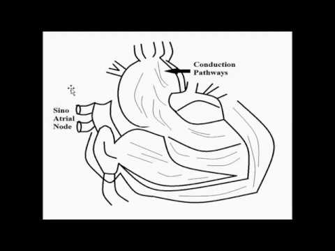
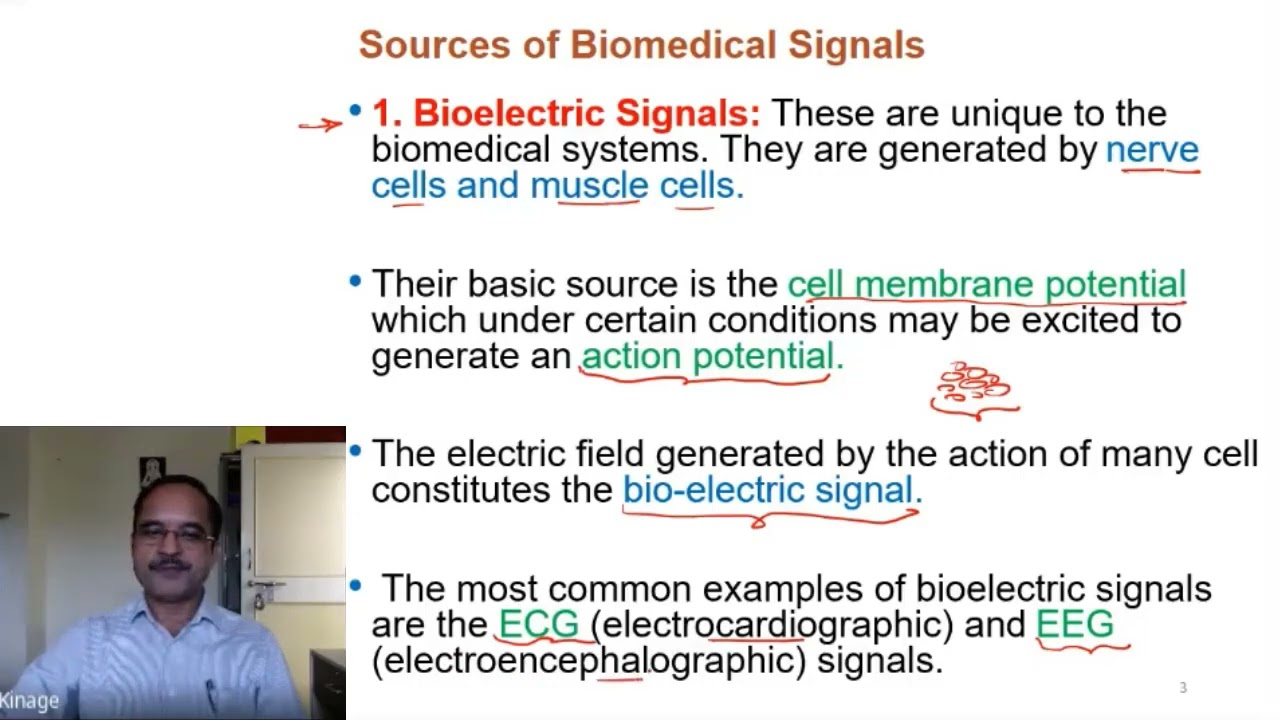
Added:Fundamentals of biopotentials and the origin of electrocardiogram (ECG) signals, including typical amplitude and frequency ranges.
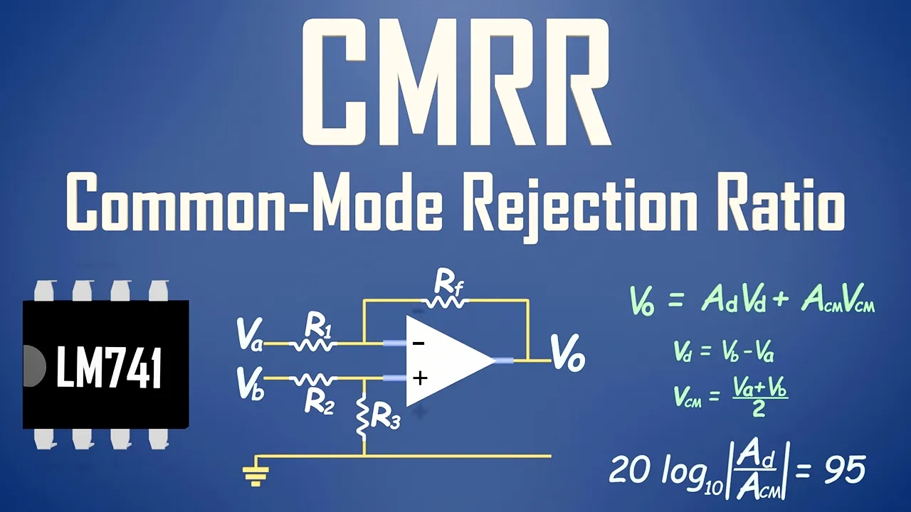
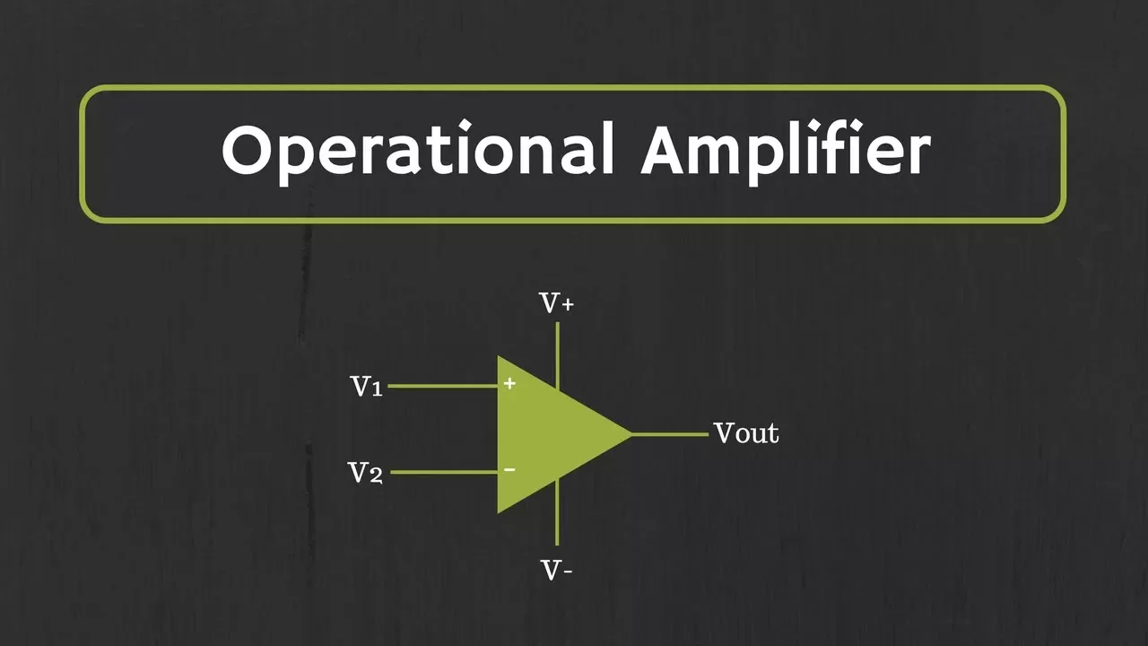
Operational amplifier (Op-Amp) theory and the operation of Instrumentation Amplifiers (InAmps), focusing on Common-Mode Rejection Ratio (CMRR).
Analog filter design principles, specifically passive and active low-pass, high-pass, and notch filters for noise attenuation.
Basic dual-supply DC power distribution and voltage regulation concepts in analog circuit design.
Printed Circuit Board (PCB) layout techniques for high-precision, low-noise mixed-signal designs, including shielding, guarding, and ground isolation.
Interfacing the analog front-end with Analog-to-Digital Converters (ADCs) and microcontrollers for signal digitization.
Medical device electrical safety standards (such as IEC 60601-1) and the design of galvanic patient isolation barriers.
Digital signal processing (DSP) for biomedical signals, including software-based baseline wander removal and QRS detection algorithms.
30.8K views192likes24:44Original Release: 2014-04-27
baroro so I get a kind of daily request on this channel to do a ECG schematic um this is the second time recording this cuz I wasn't recording the video before um so without any further delays I'm going to just go through an ECG schematic design show you all the parts I use um if you want you just skip to the end of the video and just copy the schematic or you could watch me make it and learn all the cool um tricks I'm not going to explain one there's one part I'm not going to explain how it works just cuz there's so much documentation already out there um that's the right leg Drive uh so just to as this is going to be a three Channel or three lead ECG device it's going to use it's going to have dual power supply requirements but I'm going to just put a uh chip in there that takes a positive voltage makes a negative voltage I'll also explain why those sometimes don't work um [Music] and I think that's it this this will be a lot more versatile than maybe some of the ECG devices you see out there or schematics um because uh a lot of times you know you'll see these three-lead ECG devices and if you use you know some different Electro placement like you have to have one on your wrist or both on your wrist and then one on your leg which is pretty uh big spacing um so this one I don't know what I'm trying to say this one's goingon to you don't have to use that spacing all right so let's get started there's really two parts um that are critical to this one's the 8620 this is oops this is a instrumentation amp and I'm using uh Eagle cab you can get a free version um if you just Google like eaglecad software or something maybe I'll put a link in in the description probably not um so this is a it usually I think this is three opamps that are built in that just take a differential from the outputs from the inputs um the other one I'm using is the op97 this is just a uh single opamp in a package um but it has some pretty good uh results all right and just because the way Eagle's set up I like to place all my place a resistor and capacitor and then just copy those whenever I need another one instead of going back and forth to the library uh so in Eagle if you go to the library called RCL I like the European symbol of capacitors so I'm going to try to make this surface mount in 042 uh smt components so all my passive like resistors and capacitors will be 0402 which refers to their Dimensions it's a four Ms by 2 Ms and if you need further explanation a m is a thousandth of an inch okay so I'm going to have a resistor here for my gain um and then we have our right leg drive and this is the part I'm not going to really explain I'm just going to build it uh if you want further explanation uh there's plenty online right anyway basically what it's doing is just it's using an opamp to drive ground to whatever electrode uh is connected to the output um and that brings up another point where um and this is something I recommend going to uh your Eagle Library your own personal library and making a component that's a hole for your electrodes let me make sure I'm recording okay I am okay good I don't want to do this a third time um so I just made a component that's a hole and I'm going to place three so this is the right leg drive I'll put the the actual values at the end for the resistors and capacitors um we're also going to add something to make this actually work if you do um locations other than the wrist and the leg uh but for now I'm going to draw it like this let's see okay so we have our leg right leg drive we have this electrode which is our ground electrode then we have two differential electrodes one here connecting to pin three and then one here connecting to pin two of our 8620 another thing add is you want the most sensitive ad620 you can get I forget what it's called maybe arz or something there's basically you want to look for one that has the lowest voltage offset input offset um that means basically what voltage does this have to be in order for this thing to pick it up um and if you're trying to do ECG on locations like if you want all your electrodes in some area on the chest you want your most sensitive uh ad620 you can get um let's see now we need ground I forgot okay um now let's make some Nets um wait a minute I did that backwards hold on no this guy is like that sorry positive input or non-inverting input as it's actually called uh goes to ground and there's two pins I don't connect to anything on the op97 pin 1 and pin five uh you really don't have to use this opam um it's one I used so take that as you will and for this we're going to use a negative um Supply so let's call this neg uh actually let's call this vsss and we'll call this vdd vdd is our positive one and over here we're going to call this vdd and this vsss let me Place some labels okay uh and our reference we're going to have that um connected to ground okay that part looks good now let's do a little bit of filtering um so we haven't so the best way to do this is to put a notch filter for the 60 HZ noise um but maybe instead of thinking this is a completed uh ECG this is more like the front end so this will give you a pretty nice signal um you know compensated for uh DC offset and a little bit of 60 HZ and anti-aliasing uh rejection those are big words all right so I've just put some passive low pass filters so this is just going to get rid of some 60 HZ noise um and now let's add a bias so usually this goes to a microcontroller um and then you could do digital filtering of this that's what I recommend um that's enough analog filtering for this system probably um so in order to go to micr controller you know I don't want this to be a negative voltage I want to make sure uh that we're not dipping below zero volts um because we do have a negative voltage supplying uh so this is going to add a bias the way that I like to think about this um maybe it's the wrong way but it works uh basically think of this as a high pass filter so highpass filter gets rid of your DC offset so it brings it down to um ground uh and if in a normal high pass filter you have your cap connected to a resistor going to ground so if you were to change that ground attached to the resistor to half of your supply voltage um let's say you had three volts and you put 1.5 volts instead of that ground then you you bring your signal to that 1.5 volt level and attenuate any offset from that so instead of attaching to vdd divided by two we use a resistor divider Network um so I'm going to call this bdd and there you go so R9 and r10 will be equal values so this will be the Junction in between them will be um or I'm sorry the The Junction that the equivalent resistance is going to hit will be half of vdd or something like that I don't know um it works so we'll call this output okay so now let's put some values in this is your gain R1 so I would put a potentiometer could put like a 10K pot um right now I put a 6 kilm resistor in there I don't trying to remember what the gain I actually used was you know I think I had actually it this all actually depends on your Lo like 6 Kil ohms probably fine for your wrists if you're going to like a chest region I'd use like 50 ohm or 10 ohm or something really small to make the gain really huge because you're basically going to have a really small signal um let's leave it to 6K hopefully you watch this far in the video and actually hear that and don't just copy um um everything I'm doing okay so make this 22 kiloohms oops uh think this is 10K and I can't remember exactly what I do but I think it's you can change these passive filters but I think I do 8 kiloohm one microfarad uh for this you can just use maybe a one microfarad and then I like to have a high resistance so I don't waste power so 100 kilohms is fine um okay so let's add a negative so we have a negative Supply but we want to use one battery um and the component that I use for that is uh well there's the max 1044 and then there's uh pretty much a synonymous version called the ICL 7660 um I don't know if that's a later version of it it's exact same pin out works pretty much the same it's a this is a DC todc charge pump inverter 66 and we're going to place this here um I'm going to design this for a 3vt supply so I'm going to use the LV pin so I'm going to ground it if you're not not using something below I think 3.5 volts um then you would just leave that floating I think what that does is increases the switching frequency for lower voltages um I think uh so let's grab this capacitor all right so this thing requires an external capacitor we're going to use 10 microfarad believe that's what they recommend in the data sheet ground ourv out we're going to call um vsss need to power it with vdd and we should add a decoupling cap this is kind of a large to cou and cap because these things don't always switch fast enough um okay so we have our negative Supply over here being generated um let's Place some holes for a battery oops and this is something I made myself my own Library um so I just have two holes here most of the time in my designs I have a regulator uh so the battery is going to a regulator uh so when the battery droops it's not drooping everything else um but for this we're just going to assume you're using a power supply okay so your battery hooks onto these two holes one goes to the ground one goes to vdd um so the last thing to add is this won't work um if you put it in like regions other than the wrist and the leg and this won't work that well either um so the thing we're going to change is it won't work that well in those locations that it does work so we're going to add a filter before it even hits oh whoops before it even hits our instrumentation amp um so we have be careful when doing this because uh you don't want to change the impedance very much from the body to the instrumentation amp um we basically want to keep that the same so we're going to do is add a filter that gets rid of the bias so we can add more gain um but also we're going to make it uh have very high resistance values and very low capacitor values and I'll explain that a sec so we're going to have a cap oops let's make this a 0.3 microfarad capacitor and then we're going to make this a 20 Mega Ohm resistor so basically the capacitance isn't going to do much we're going to have to wait for that capacitor to charge before we actually get signal so this might take a couple seconds before you see anything um and this resistor isn't going to divert much current because it's very high resistance you might even want to do higher than 20 megaohms um because this actually is affecting the the internal resistance of the 8620 um because it probably has a quite a lot of Mega ohms um basically we want something high so we don't draw current from the body or a lot of current because you can't really Source current from the body um okay so now let's do that for the other one let getting kind of crowed um yeah that's it oh so couple notes go and take your screenshots um uh let's see basically when you're making this on a layout don't use a tin finish board or your there's several things that won't work actually actually nothing will work um if you don't have a good PCB that you're putting this on the impedance from uh the body to the instrumentation amp is increased basically that solder joint um from the PCB to the leg of the instrumentation amp um that because that solder joint is crappy and oxidizes very quickly the impedance goes up um and you basically get no signals you also won't get a negative Supply working if you have a um cheap PCB so get either a enig PCB um which is emerging nickel over uh electris wait emerging gold over electric nickel electric nickel I think um or solder finish PCB um I think that also goes by the name of opt or something let's check OSP sorry um cool so now you can stop bugging me for this schematic ciao
Up Next

36:53
Second Order KRC Band Pass & Notch Filter Design Using Opamp
@InderjitSingh87
1.1K views•2020-12-06

30:32
Ultrasonic Transducers: Resonant Frequency Measurement and Horn Design
@imajeenyus42
229.9K views•2017-02-22

54:16
Polymer Environmental Degradation: Mechanisms & Stabilization
@iit
1.8K views•2012-07-10

33:39
How a Student's Question Saved a NYC Skyscraper from Collapse
@veritasium
22.8M views•2025-04-26
Related Study Plans & Knowledge Roadmaps
Structured learning paths in Engineering
engineering
Building Acoustic Levitators: Physics & Arduino
01The Physics of Sound and Standing Waves
02Piezoelectric Transducers and H-Bridge Drivers
03Arduino Programming: Generating 40 kHz Signals
+ 2 more learning modules
14h5 modules
Explore Roadmap
engineering
Building Peltier Cloud Chambers: Particle Tracks
01Cosmic Rays & Cloud Chamber Physics
02Thermoelectric Cooling (TEC) Fundamentals
03Custom Liquid-Cooling Loop Design
+ 2 more learning modules
18h5 modules
Explore Roadmap
engineering
Yagi-Uda Antennas: Modeling, Build & VNA Test
01Introduction to RF and Antenna Fundamentals
02Yagi-Uda Antenna Design Principles
03Antenna Modeling and Simulation in 4NEC2
+ 2 more learning modules
18h5 modules
Explore Roadmap
engineering
ECG Monitor Design: Op-Amps, Filters & Noise
01Electronics & Breadboard Basics
02Op-Amps and Instrumentation Amplifiers
03Bioelectricity and ECG Fundamentals
+ 2 more learning modules
18h5 modules
Explore Roadmap